Posted on Leave a comment

Bore Vs. Stroke — Which One Is Worth More Power?

One of the basic tenants of hot-rodding is finding ways to add more power. One popular way of doing that is by adding displacement. To do that there are two dimensions in an engine’s configuration which determine displacement: the engine’s bore and stroke.

At the risk of stating the obvious, the bore of the engine is the diameter of the cylinder (and the piston inside of it), while the stroke is the vertical distance the piston travels within the cylinder. There are lots of debates, both in real life and on the internet, about which dimension is worth more power.

Enter Jason Fenske of Engineering Explained. With his desire to explain how pretty much anything and everything automotive works, he’s taken on the subject. “If your goal is to create as much horsepower as possible, there are reasons why it is advantageous to go with a larger bore, relative to the length of stroke,” Fenske starts out. However, if your goal is to create an engine that is as efficient as possible, there are reasons to go with a longer stroke relative to the bore.”

In order to fully illustrate the differences, he has come up with some rather extreme examples on either end of the spectrum (more than boring a factory engine .040-inch over, or adding 0.5-inch of stroke).

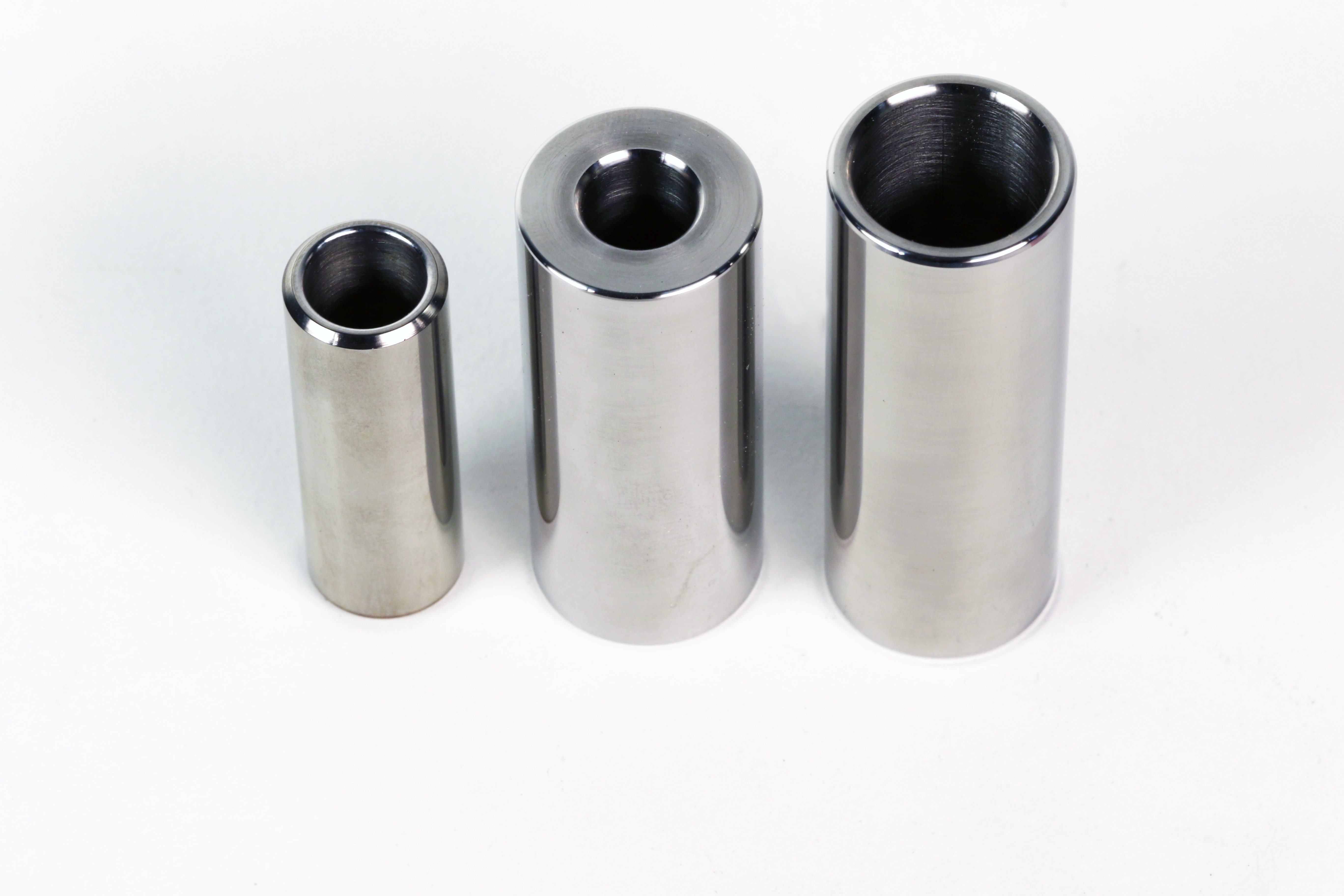
Here, you can see the dimensions of the example cylinders used in all the calculations, all of which measure out to a 0.5-liter (30.5 ci) displacement. On the left is a cylinder larger than, but with the bore-stroke ratio of an F1 engine, A typical square cylinder found in many 2.0-liter I4 and 3.0L V6 engines, and an exaggerated long-stroke cylinder having the opposite bore-to-stroke ratio as an F1 engine.

“For the purposes of this discussion, we’ll discuss three cylinders all with the exact same displacement. All will have a half-liter displacement, and the middle of the road example will be square at 86mm (3.386 in.) bore and 86mm stroke. The 0.5-liter square cylinder is one that you will find in many roadgoing engines, especially 2.0-liter I4s and 3.0-liter V6s,” says Fenske

For the oversquare (bore larger than the stroke) engine example, Fenske has created a 117mm (4.606 in.) bore, 47mm (1.850 in.) stroke cylinder. “That puts the bore-to-stroke ratio similar to an F1 engine,” Fenske explains. “Typically, F1 cylinders wouldn’t be this large, but these dimensions keep the cylinders equal displacement for the example.”

For the undersquare (stroke larger than the bore), another cylinder of exaggerated dimensions was created, with a 63mm (2.480 in.) bore and 158mm (6.220 in.) stroke. This cylinder has a reverse bore-to-stroke ratio from that of an F1 engine,” says Fenske. “A 63mm bore with a 158mm stroke is far from anything you’d typically in a roadgoing car, but it will help illustrate the points.”

Making Horsepower

One thing to remember about horsepower, especially when chasing it, is that it is a calculated unit, and is essentially torque over time. “One of the critical things about horsepower is, how fast can you rev your engine,” says Fenske. “It is a function of torque multiplied by RPM, multiplied by 5,252 (assuming English units). If torque is held constant — which isn’t easy to do — horsepower is simply a function of RPM. If you can rev your engine higher, you can make more power, and that’s the ultimate goal.”

There are a lot of factors that determine maximum engine speed, but for the purposes of this hypothetical discussion, Fenske chooses to use piston speed as the ultimate limiting factor of potential hypothetical engine speed.

“By decreasing your stroke length, you’re able to increase your RPM limit. Automotive engines don’t typically exceed 25 meters-per-second. Once you exceed that limit, you start to run into issues. We can calculate average piston speed for the different examples fairly easily using the following equation:”

“If we know the piston speed, we can plug that in and then do some dividing and figure out maximum RPM based on stroke length,” explains Fenske. “For the oversquare cylinder, we get a maximum RPM of 16,000. For the square cylinder, it’s about 8,700 rpm, and for our undersquare cylinder, our limit is going to be about 4,700 rpm. Because the shorter stroke configuration can rev higher, it has more power strokes per second, and therefore makes more power.”

Fenske notes, that just because the engine configuration can rev to 8,700rpm without overspeeding the piston, doesn’t mean the engine will rev that high. There are other limiting factors besides piston speed.

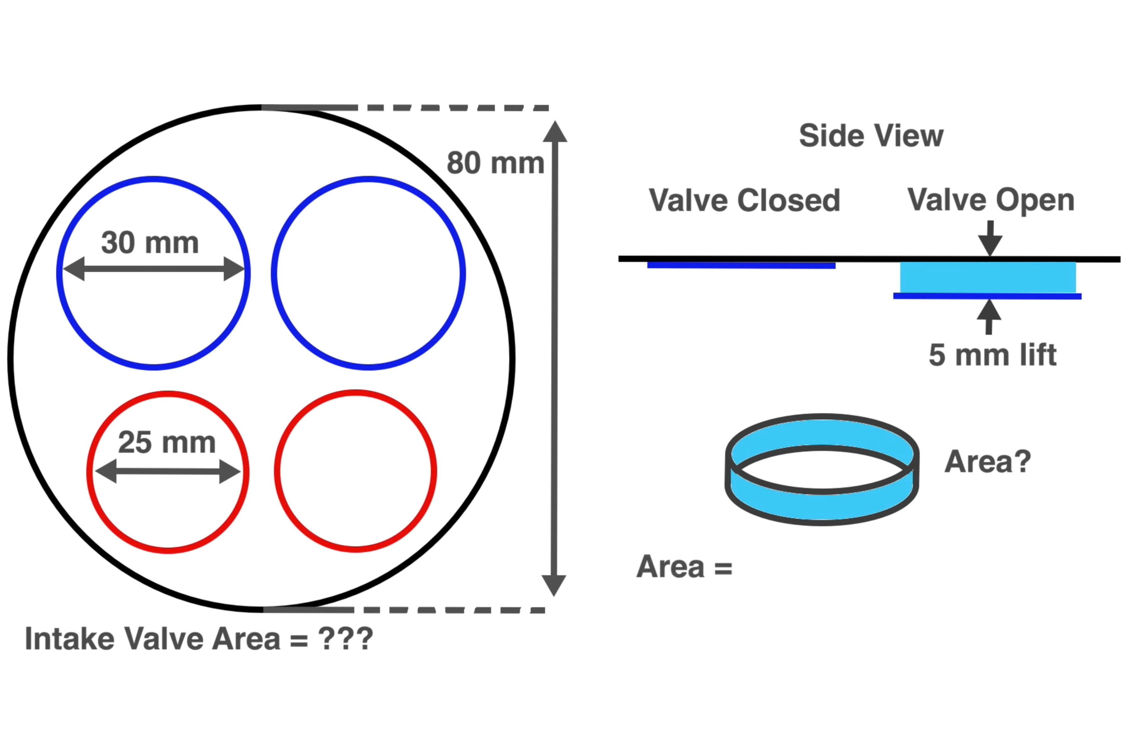
The second advantage of a big-bore setup is its physically-larger size. “This has to do with the size of your valves and how much airflow we can get through the engine,” says Fenske. By being able to fit physically larger valves, you are able to move more air into and out of the cylinder.

“Starting with an example of an 80mm-bore engine, we’ll say it has two 30mm intake valves and two 25mm exhaust valves. Using that example, we’ll scale it to our cylinder examples,” Fenske postulates.

“After scaling, the largest cylinder has two 44mm intake valves versus 24mm intake valves on the small-bore example, and the exhaust valves are 37mm on the large bore example, and 20mm on the smallest. Now, giving these exhaust valves the exact same amount of lift (5mm), the intake valve area of the largest example is about 25.2 square centimeters; he 86mm example is 18.6 sq-cm, and the 63mm bore, you get about 13.7 sq-cm.”

Obviously, being able to move almost twice the amount of air is an advantage for the larger bore in this example, but in practical applications, the difference between “small bore” and “big bore” is far less drastic. However, Fenske does bring up a good point in the video about the large valves and reduced volumetric efficiency at low-RPM, but that’s a rabbit hole for another day.

In addition to having a shorter stroke length and the associated theoretical higher RPM limit, the larger bore allows for larger valves to fit in the cylinder head, which in turn increased the engines maximum airflow potential.

Creating Efficiency

Sometimes, all-out horsepower isn’t the goal, and the goal is to have an efficient all-around performing engine, for say a street car. According to the general logic of mechanical engineering, the longer stroke provides that efficiency over a bigger bore.

“One of the reasons I’ve often heard for why long stroke engines are more efficient, is that the amount of surface area they have, relative to the volume inside of the cylinder I low, meaning there is less overall area to reject heat to, during combustion. That means more of that heat is turned into useful work pushing the piston down,” says Fenske.

“Calculating the surface area for our examples is easy enough, and we find that the oversquare engine has a surface area of 386 sq-cm, the square engine has a surface area of 349 sq-cm, and the long-stroke has a surface area of 378 sq-cm. So we see that as you move either direction away from a square engine design, you start to get more surface area.”

Those numbers may seem to not support the idea that the longer stroke is more efficient. However, Fenske points out the flaw in using the total swept area of the cylinder. “You have to factor in compression ratio and what the cylinder looks like at the time of combustion,” he explains.

“The undersquare cylinder is actually the closest to square (at the time of combustion) in this example. Running the numbers at the point of combustion, you see that the long-stroke cylinder has the least amount of surface area, and is now turning the most heat from combustion into usable work.”

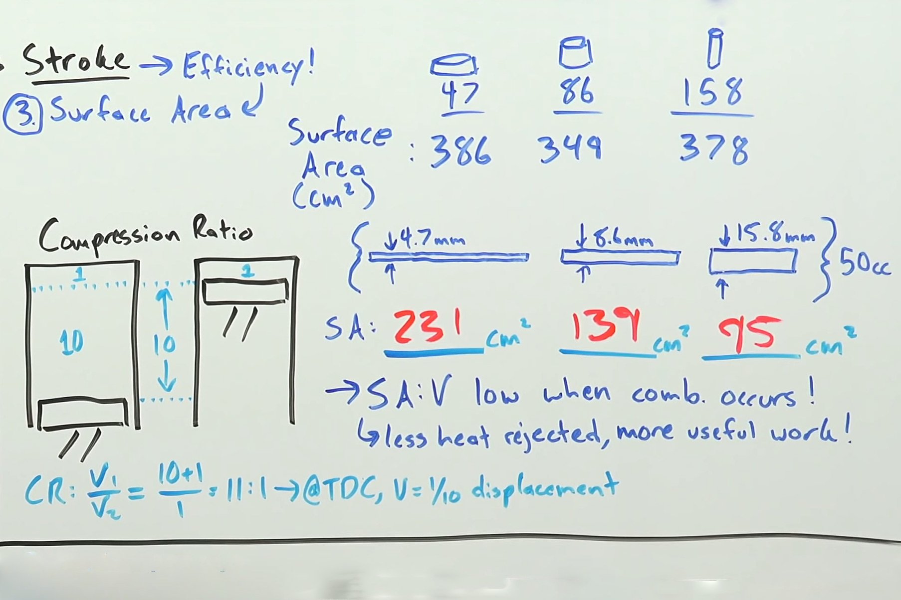
The numbers in the upper right (386, 349, and 378) show that total surface area increases the further you get from a “square” configuration. However, factoring in the shape of the cylinder when combustion occurs, (mid-lower right) shows that the long-stroke cylinder is actually the closest to square at the point of combustion, making it the more efficient design.

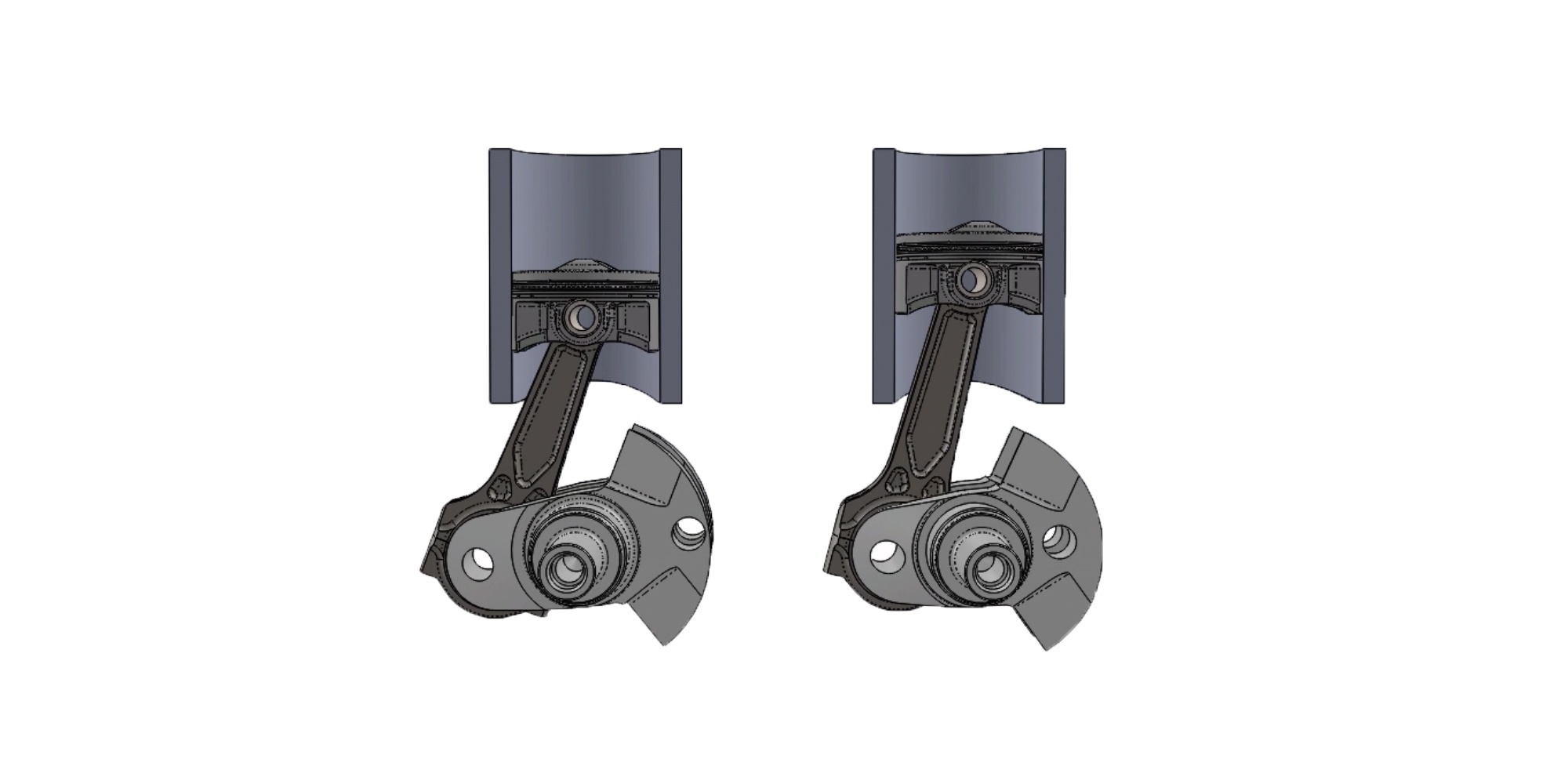
Tied into that is also burn duration, which, we’ll warn you, gets complex. “The logic here is that the quicker you can burn the air-fuel mixture, the more efficient of an engine you’ll have. The simple answer here as to why a small-bore, long-stroke engine burns the charge faster, is that the flame front has less distance to travel,” says Fenske.

“By the time the flame front has reached the cylinder wall of the oversquare engine, the piston has moved further down the bore that in the smaller-bore cylinder, and you get less efficient combustion.”

If you really want to dive into some of the heavy lifting on the burn-duration subject, jump to the 11:34 mark in the video, where Fenske talks about a study he found and explains the results they published. It’s interesting, for sure.

While these examples are more illustrative than practical, they do get the differences in bore and stroke across in broad strokes. Fenske does end the video with a disclaimer, saying, “There are of course exceptions to everything we’ve discussed. Just because an engine has a large bore, doesn’t mean that it can’t be efficient. Just because an engine has a long stroke doesn’t mean it can’t make a ton of horsepower. But if you isolate those variables individually, this is what you’ll see.”

The simple explanation of burn duration in the upper right corner shows that the flame front simply has less distance to travel for a complete burn. The illustration in the lower-left corner relates to the study Fenske came across from the Southwest Research Institute and is pretty interesting, if not deeper in the scientific weeds than we can get into here.

--   Regards,    Barry Gilkes  Max Torque Performance  P: 1-246-2343235  http://maxtorqueperformance.com

Posted on Leave a comment

The Art And Science Of Cylinder Honing

The whole idea behind building an engine is to capture as much air and the proper ratio of fuel in the combustion space as possible, squeeze it, light it off, and use the combustion to make pressure and power. One of the best ways to optimize that pressure is not to allow it to leak past the rings. This calls for not only a round cylinder but also one that offers the proper wall preparation in terms of a cross-hatch pattern and texture.

While this sounds simple, the execution of the process calls for some serious attention to detail. It doesn’t make much sense to invest thousands of dollars in trick pistons, rings, cylinder heads, valvetrain, and induction only to scrimp on cylinder-wall preparation. This installment of the EngineLabs Blueprint Series will introduce some current ideas you should seriously consider for your next performance engine build.

A Honed Edge

As a generic definition, the goal for a completed honed cylinder is to establish a perfectly round bore, sized to give the proper piston-to-wall clearance, with a given cross-hatch pattern and roughness. In addition to being perfectly round, the cylinder also needs to be perfectly straight in relation to the crankshaft.

QMP prefers to use its own custom-designed torque plates. Notice the fittings on these plates that, when connected, can circulate heated cutting oil through the plate when the block is honed at temperature. We did not choose this feature as it nearly quadruples the price of honing.

The honing process employs a honing stone of a certain grit applied with precise pressure and speed, to create the desired cross-hatch pattern. The pattern on the cylinder-wall allows the rings to seal after a short break-in period while retaining enough oil to lubricate the piston and ring package properly.

Accomplishing the proper hone is more difficult than it might appear. When racers first started experimenting with cylinder bore finishes, their early efforts were aimed at creating a near-polished surface. This turned out to be less than desirable.

Later experiments revealed that a more optimal surface finish has a few microscopic peaks combined with deeper valleys. This offers the opportunity to store sufficient oil in the valleys to lubricate the rings while still providing a smooth enough surface to seal the rings to the bore.

This approach created what was first called a plateau finish back in the 1980s. The idea was to create the surface through a process first using rough stones to create the deeper valleys, followed by progressively-finer stones, combined with reduced load on the stones to flatten the rough peaks of the surface while retaining sufficient valley depth to lubricate the rings.

This is QMP’s Sunnen SV-10 machine used to machine our Dart Sportsman iron block. Older hones use four stones. QMP’s SV-10 uses eight diamond cutting stones as opposed to more traditional abrasive stones.

Setting Things Straight

Some of the earliest advances in ring-sealing science occurred when engine builders discovered that the cylinder becomes significantly out-of-round when the head is torqued to the block. To recreate this distortion during the honing process, thick torque plates are bolted to the block. These plates have openings in them, allowing the hone to access the bores.

The next logical step in the development process was to circulate hot coolant and/or oil through the block and torque plates to bring the block up to operating temperature, which simulates the block’s thermal distortion in the real world. We’ll save the exact details on how much that process is worth for a subsequent story, but the improvements are significant.

Perhaps the most impactful advancement beyond torque plates for the street engine builder is the integration of computer numerical control (CNC) over honing machines. Our recent experience with a Sunnen V-10 machine at our local machine shop revealed just how sophisticated this process has become. These advanced digital machines can now measure the actual concentricity and straightness of the cylinder DURING the honing process.

Lagman built a fixture to mount the Mitutoyo profilometer to the block. This puts the profilometer in the same place every time to make measurements more consistent. This simple-looking device is what delivers the micro-inch readings to the computer, but it costs more than $2,300.

One aspect of cylinder honing often overlooked is how much the cylinder bore distorts — just from the action of the hone itself. It’s common to demonstrate bore straightness by using a dial bore indicator at various depths within the bore. While these measurements are accurate, they do not indicate whether the bore is vertically straight because each is a single point measurement.

A Different Kind of Stack of Dimes

An example of this is our photo of a stack of dimes. Let’s assume for a moment that this stack represents a cylinder of a given depth and each of these dimes is precisely the same diameter to 0.0001-inch. Let’s also assume that a dial bore measurement is performed on each individual dime. If the stack is offset as shown in the photo, the bore will measure the proper size at each particular measuring point, but in reality, it is closer to an “S” shape.

Imagine this stack of dimes represents an exaggerated view of a cylinder wall. If we use a dial-bore gauge to measure the bore at a point represented by one dime and all the dimes are the same diameter, the bore might appear straight. But, this stack would indicate that the bore is anything but “straight”.

The latest digital honing machines from Sunnen, Rottler, and others will display the bore straightness as the hone is operating. Watching this can be a bit disconcerting as you see how much distortion really exists. These are expressed in shapes like a triangle (too small at the top or too large at the bottom), a barrel (too wide in the middle), or variations such as an hourglass or parallelogram. The machinist’s job is to minimize these distortions to create a truly “straight” bore.

This might also be a good place to mention that much of what we will discuss here is aimed at higher-end performance engines. This is not to infer that machine shops using older manual honing machines are not capable of doing quality work. Often, these shops are staffed with machinists having decades of experience honing blocks, who can deliver a high-quality finish-honed block that is as straight and round as they can make it, and with an excellent finish to boot.

QMP’s digital SV-10 hone offers this real-time display of the bore shape. This is one cylinder in our block that displayed three separate bands where the bore was not concentric. The machine automatically compensates with load and position to bring the bore into concentricity top to bottom. It really is impressive to watch this happen.

Stylin’ and Profilin’

Taking the above concepts one step further, there is no replacement for being able to measure the results of a honing process beyond just bore size and straightness. Among the more significant advances in cylinder honing is a highly specialized tool called a profilometer.

This is a precision measuring device that can quickly evaluate the surface roughness of a cross-hatch pattern. The tool precisely measures the surface texture of the bore, and an end-user now has a highly accurate evaluation of the cylinder’s honing process. So, let’s get into a short explanation of these evaluations.

These descriptions come from the American Society of Mechanical Engineers (ASME), but rather than get bogged down in molasses-in-winter math, we will give you the abbreviated Cliff’s Notes versions of these evaluations. The measurements we will work with most are Ra, Rk, Rpk, Rvk, and the Mean Line.

This is the report screen from QMP’s Mitutoyo profilometer after honing was complete. The jagged line in the upper left is the overall profile that reveals the peaks (Rpk) and valleys (Rvk). In the lower-left area is the numerical report. If you think this looks complex — you would be correct!

Micro-Millions: Measuring Surface Roughness

All numbers used in conjunction with these descriptions are expressed in micro-inches (abbreviated “µin”), which is one-millionth of an inch (0.000001-inch). As an example, if the Ra for a cylinder wall was 15 micro-inches, it would be expressed as 15 µin (0.000015-inch).

There are several other values that take the express elevator farther down the rabbit hole than we prefer to go, so we’ll limit our discussion to the four values that revolve around the mean line. Keith Jones of Total Seal helped us with these descriptions to make sure we got this correct.

“Ra” is used to describe the overall average roughness of a cylinder wall. Ra is so generic that it has little useful application for cylinder walls. More helpful is the “Rk” number, which is the core roughness of the surface above what is called the “M line.” The M line is the mean, or the arithmetically-created middle line between the peaks and valleys, which is used as the baseline for measuring all of the following descriptions.

The Rk, or core roughness depth, is the description of the surface that will support the majority of the load. Think of this as the roughness of the base of the cylinder wall that the ring will slide across.

This drawing illustrates the relationship of Ra, Rvk, and Rpk to the M-Line over a given linear distance (L).

“Rpk” is the reduced-average roughness of the peaks created by the honing process. The Rpk numbers protrude above the Rk core surface This number indicates the average peak heights, which will wear down as the rings slide up and down the bore during the break-in period. A larger number indicates taller peaks while a lower indicates shorter peaks.

As you can probably guess, the “Rvk” number represents the reduced-average valley depth within a given lateral distance. These valleys extend below the Rk surface. A higher Rvk number — also expressed in µin — is equivalent to deeper valleys where more oil will be located. A good machinist will use a profilometer to measure the surface texture of his cylinder wall and adjust the roughness of the honing stones, the speed of his machine, and the load applied to the stones to achieve the desired surface finish.

Total Seal Honing Recommendations

General Purpose High End Big Boost
Rpk 8-12 7-10 10-15
Rk 30-35 18-22 35-40
Rvk 40-45 28-32 50

*All numbers expressed in µin

From Theoretical to Practical

None of this information means much unless we can offer some examples. Several variables affect the desired numbers, starting with the hardness of the cylinder wall. Later model blocks like GM’s LS engines and most aftermarket blocks are cast from much harder iron than the engine blocks from the 1960s.

Another huge variable is how the engine will be used. Total Seal has chosen to identify three basic performance categories. Street engines would likely fall under Total Seal’s “General Purpose” class. Next would be Total Seal’s “High-End” classification, encompassing normally-aspirated competition engines. The top tier is nitrous and supercharged applications which Total Seal calls “Big Boost” applications.

We’ll offer some simple numbers for a given street engine. We’ve listed Total Seal’s honing recommendations in the included chart using the above three categories. Perhaps the best thing to take away from this is that creating the proper honing numbers for the appropriate rings depends largely on the way the engine will be used. One size, or in this case one honing plan, does not fit all.

In terms of engine break-in, higher-quality rings like Total Seal’s Advanced Profile (AP) rings are lapped to an optimal surface and, therefore, are literally already broken in. Because of this, the cylinder wall Rpk numbers can be reduced because the taller peaks are not required to help seat the rings. By the time the engine starts and runs for a few moments the rings are “broken in,”

We recently delivered a Dart Sportsman iron Chevy block to Brad Lagman at Quarter-Mile Performance (QMP) in Chatsworth, California to apply the final hone for an upcoming Total Seal ring test. Since the testing will include a set of ultra-thin AP CrN-faced rings, Lagman set up our block on his Sunnen SV-10 diamond-hone machine to address the cylinder walls.

If we compare the numbers generated from QMP’s profilometer on this block to the Total Seal numbers for a modern SV-10 Sunnen machine, we can see that Lagman did a really great job on the block. Our Rpk numbers are just slightly smoother than Total Seal’s General Purpose numbers while the Rvk values are slightly on the deep side of the General Purpose numbers.

QMP Dart Block Final Hone Results

Micro-Inches 
Rpk 5.6
Rk 26
Rvk 48

This will place slightly more oil in the valleys, which should offer excellent lubrication to the rings while not creating a situation where oil usage might be a problem. The Rk numbers fall almost halfway between Total Seal’s “General Purpose” and “High End” values.

Looking at the Rk numbers more closely, our final number is lower, making it slightly smoother than the General Purpose numbers. This should improve the ring seal and help to minimize friction.

There’s far more to this subject than the introductory amount we’ve covered here, and we’ll save some information for a more in-depth story. In the future, we’ll look at specific honing techniques and other fascinating aspects of the process, such as what happens to a cylinder bore when the block is heated.

Everybody knows that ring seal is essential, but these highly specialized profilometer measurements become increasingly critical to properly sealing the rings to the cylinder wall in high-performance, high-cylinder-pressure applications. This is all part of what it takes to hone a block for a performance engine properly.

Older machines like this Sunnen CV-616 analog hone can still produce excellent results at the hands of a qualified and experienced operator.


Posted on Leave a comment

Five Things You Need To Know About Aluminum Connecting Rods

When you’re building an engine for a project there are limitless possibilities of parts and combinations you can use. If you’re jumping into the higher end of the horsepower pool you might be looking at using a set of aluminum connecting rods to swing your pistons inside the cylinder bores. Aluminum rods have long been a topic of debate in regards to their use and longevity in varying types of racing engines. Depending upon purpose, budget, power adders, and other variables, aluminum rods can be a great addition to any engine, but are they for everyone? And do today’s latest variants eliminate such concerns as rod stretch?

Anthony Giannone from MGP Connecting Rods joined us to illustrate the top five tips for buying aluminum connecting rods.

#1: Understand The Benefits Of Aluminum Rods Before You Spend The Money

If you’re making the investment to build a killer engine you want to pack it full with the best parts possible. The problem with that mindset is that you may end up buying parts that aren’t the best fit for your goals or the combination. Aluminum rods may seem like something you need because they’re shiny and fast guys use them, but you need to know if they’ll work for your build first.

Aluminum connecting rods do provide performance advantages, but it’s important to ensure they’re the right fit for your combination.

Anthony has helped countless racers create engines that make enough horsepower to rotate the earth many times over and he provides a great explanation of aluminum rod basics.

“Aluminum rods are essentially shock absorbers. They’re intended to take all of the compressive load and not transfer that energy to the crankshaft; that was the original thinking behind the aluminum rod. So with that said, now anything that has a power-adder runs on detonation, and when you’re detonating that hard, a steel rod can’t live through that without failing.”

 The aluminum rod benefit is the ability to take that hit of energy and save the crankshaft. It’s a lot easier to justify a $1,200 set of rods than it is a $5,000 crankshaft if you need to replace something. – Anthony Giannone

The advantage that has been preached about aluminum rods since they were first introduced was the weight savings they provide. While aluminum rods can save you weight, they can also add strength to the right places.

“The topic of weight isn’t nearly as big as it used to be. Steel rod manufacturers have been able to remove a lot of weight in their modern designs, and aluminum rods are about 100 grams lighter in a direct comparison of similar rods. Engine builders are trying to get more weight off the piston these days and keep the extra mass at the bottom of the rod — that’s where an aluminum rod is beneficial. There’s a lot more material at the bottom, so they are still stronger for their weight compared to steel rods,” Antony says.

#2: Aluminum Rod Stretch And Growth Be Gone!

Rod stretch and growth used to be a legitimate concern for those who wanted to add a set of aluminum rods to their rotating assembly. Basically, rod stretch is the physical stretching of a rod’s center distance. An engine builder would have to take the stretch into account because the rods would grow as the engine increased in RPM. If the stretch and growth weren’t compensated for during the design of the engine package, when the rod would eventually stretch it would cause the piston to make contact with things it shouldn’t.

Anthony explains that at MGP, they don’t see rod growth anymore and assist their customers in making sure they have the right size rods based on this.

“People used to compensate anywhere from .010- to .015-inches center distance for growth that would occur when using aluminum rods. We recommend .050-inch piston to head, and that’s whether they want to put it at zero deck and run a .050-inch gasket, or put it in the hole .050 and run a .010 gasket. We just don’t see the rods stretching on the center distance like they used to. That distance is there just in case, because when we get rods back we don’t see them stretching really — they still have the same center distance we sent them out with.”

A blown Pro Mod engine like the one Mike Janis uses in his Camaro needs aluminum connecting rods due to the violent nature of the combination. The aluminum rods help to keep the rotating assembly happy and spinning as it should.

The rod stretch and growth plague might not be something you have to worry about as much anymore, but it took some work to get rid of. MGP spent a considerable amount of time working on finding a way to eradicate the problem so aluminum rods could become more practical for all applications.

“We eliminated that problem through design partially, and a lot through the materials we implemented into our products. The aluminum we use is an aerospace-quality material that is the most current aluminum to come to market. The material is what was causing the majority of stretch issues, and our new materials don’t have that issue. Getting rid of rod stretch and growth provides a performance advantage because people can run at zero deck and only have to run a .050-inch clearance,” Anthony explains.

#3: Torque Method versus Stretch Method For Rod Bolts

If you plan on building or maintaining an engine that uses aluminum rods you need to know how to properly torque the rod bolts. There are two different ways to do it: one is where you measure the amount of stretch once the bolt is tightened, and the other you torque the bolt down to a specific foot/pound measurement.

The stretch value of the rod’s bolt is important, because that is where the yield point is for the bolt, and it can’t be exceeded. If the bolt is stretched beyond its yield point, it will actually become physically longer and that will lead to it becoming weaker or having an uneven load put on the rod’s cap.

We use a torque value for our rod bolts, so both sides of the rod and both bolts are to the exact same foot/pound of torque. -Anthony Giannone

Using the torque method, you’re only torquing the bolt down to the specific amount the manufacturer recommends. You don’t have to worry about chasing a stretch value number or trying to get a stretch gauge to fit in a confined space under a car if you’re doing maintenance at the track.

“We use a torque value for our rod bolts, so both sides of the rod and both bolts are to the exact same foot/pound of torque. The bolt free length varies so much with different bolts that if you’re going off of stretch value, even if you’re setting static length on it, that bolt will be physically longer. When you finish the housing bore, keeping the same compression side to side is an issue going off of stretch value. Say on one side you’re at 90 ft-lb, and on the other, you’re at 98 ft-lb…. that housing bore isn’t being pulled an even amount on both sides. That can lead to an out-of-round condition for the rod,” Anthony says.

Using the torque method with aluminum connecting rods will keep them functioning properly and allow for easier maintenance at the track.

Using the torque method allows you to have a more precise measurement. Having the correct clamping load amount and keeping it even on each side of the rod cap is important, because that’s what helps the aluminum rod function at its best.

“The clamping load being even from side to side is ultimately the key to keeping the housing bore round, and that’s where the aluminum rods shine. When that housing bore is round it’s not collapsing vertically, it’s not opening the parting line up, and it’s not squeezing bearings. If you’re out-of-round right from the beginning it will destroy the bearings — it finds a way to side-load them in a weird way, and it will wear the coatings off of the bearings unevenly in places. All of those factors contribute to an aluminum rod failing when it shouldn’t in any situation,” Anthony says.

#4: Bolt Lubrication During Installation

Lubrication during assembly of aluminum connecting rods is a task that must be taken very seriously. Since you’re using a bolt that is made up of a different material than the rod itself, something needs to be used to fill in the area between each part.

“We’re dealing with two things here: first, we have the steel-on-steel contact between the bolt and the washer. Second, we’re dealing with the steel-on-aluminum contact between the thread of the aluminum rod and the bolt. Something needs to be added that can run interference between the two different metals — that’s why we use oil, and it also helps with the pre-load. The pre-load on the fastener is what really makes the connecting rod work correctly; when you lose pre-load, that’s usually when you end up with a giant hole in the side of a $10,000 billet block,” Anthony explains.

Most people would think that it’s time to reach for the assembly lube to make sure you have the correct bolt lubrication when assembling your rods, but that might not be the ideal course of action. Anthony explains why assembly lube isn’t your best friend when putting aluminum rods together.

“When you use assembly lube on bolts and torque them down, that lube is going to come in contact with engine oil when you fill the engine up, and those two liquids don’t mix well together. The particles in the assembly lube will grab the particles in the engine oil and will cause them to separate. That’s why I’ve always been against assembly lubes — because it ruins engine oil, and it can also plug up oil gallies if there’s too much used. When assembly lube heats up it will start to thin out and you lose the value you gain from it.”

Using 50-weight oil will ensure your connecting rods go together properly and will help to avoid bearing wear.

So what does Anthony recommend for lubrication with rods? Surprisingly, the answer is just plain old 50-weight engine oil. This discovery was made after lots of testing to find a solution that would be the most consistent overall to torque down a rod bolt, because the oil remains neutral no matter what the temperature is around it.

“Zero- or 5-weight oil doesn’t stay as consistent because it is temperature-dependent. Fifty-weight engine oil is always going to be 50-weight with the same lubrication level, and has the same amount of molecules between the bolt and the rod no matter what the temperature is. It doesn’t matter if the rod and bolt are at two different temperatures, it stays consistent,” Anthony says.

#5: Billet versus Forged Aluminum Rods

You have two different options for aluminum rod manufacture: billet aluminum and forged aluminum. Forged aluminum rods are the original type of rod that was produced based on the technology that was available at the time. Now, companies can make rods out of billet aluminum, as well, and that added more options for builders.

The debate over which rod to use has always been based around the grain structure each possesses. To make a billet rod, MGP starts with a solid block of aluminum that’s 12-feet long and 3/4-inch thick. This material has grains that all run in the same direction from end to end. Making connecting rods out of this billet material wasn’t possible until the machines and processes were developed to make it happen. Now, a billet rod allows for more grain control and strength.

Modern billet aluminum connecting rods provide strength in all the right places on the rod itself.

“The grain structure rolls around the rod end just like a forged rod would with a modern billet rod. Since we’re machining the rods out of solid stock, we’re letting the grain structure flow straight and we’re just machining through the center of it. The grains run the same way in that bar from end to end and we machine with the grain to make sure there is plenty of strength,” Anthony says.

Grain structure is important for a connecting rod because it dictates the strength of the part. The cross-sectional strength of the connecting rod comes from the design, while the overall physical strength is based on the aluminum itself. Having the grain structure of the aluminum all going one way, especially around the ends of the rod, is important to ensure it will have plenty of strength. Forged aluminum rods used to be the only way to provide this, but now with modern materials technology, a billet rod can be made of aluminum that has a good grain structure for a high level of strength. The biggest difference between forged and billet aluminum connecting rods is the service life — a billet rod will have a longer lifespan than its forged counterpart.

Aluminum connecting rods have come a long way since they were first introduced as an option for a rotating assembly. Understanding the limits of the part and how it works will help you make an informed choice if you need to use them in your next build.

Posted on Leave a comment

10 Myths Of Cylinder Head Porting

­ 


About the Author: Dave Localio is a long-time friend of ours and the owner/operator of Headgames Motorworks, a cylinder head specialist founded in New Jersey in 2001. Dave and his team have amassed a huge amount of experience and expertise and are now creating some of the best performing cylinder head and cam packages for both domestic and import vehicles, be it for street/strip use or full blown race applications.

Myth #1. CNC is “better”

This one depends on the piece in the machine. If your making billet heads, the accuracy of the CNC is worth talking about, because you’re making something from scratch and making a batch of them ensures that they will all be the same. But when it comes to CNC machining a factory cast cylinder head, talking about the accuracy of the machine is a moot point. I say this because the factory head is cast, which means there will be some variation from head to head because of the imperfections that come from the casting process. That’s where the words “core shift” comes into play, because when we get cast heads back from the CNC shops there is not one that is exactly the same. In fact, in the head there is no ports that are the same. You can even see where the CNC did not touch the casting in one port but did in the others. That’s because the CNC machine does not know where the ports are, just where they are supposed to be. Meanwhile, a hand knows the center of that port every time. So, what does this mean? 

While a CNC is better than a hand at many things, when it comes to porting your factory cast cylinder head it is really just faster, meaning it’s faster than any human could grind and sand your head. So, instead of waiting weeks or months to get it back from the machine shop, someone with a CNC could rip through it in a few hours and have it on the floor ready for machine work. Talking about consistency machining an inconsistent part makes no sense except to market it as the best option. However, because there are cylinder head guys out there who do such a poor job hand porting, seemingly haven taken lessons from a blind person with a hammer and a chisel, they help perpetuate the myth that CNC porting is more accurate or “better”. 

Myth #2. Dimple Ports 

While we are on the subject, we should touch on dimple ports. The argument is that it works on golf balls because it creates a boundary layer of air and helps it move the ball faster and farther. In a port, we are looking to create a situation where fuel stays off the wall of the port. So the dimples would (in theory) help create this boundary layer of air that would keep the fuel off the wall and in suspense and atomized. 

First off, more than likely you have an engine with modern fuel injection if your reading this. Modern fuel injectors do an excellent job of atomizing the fuel, especially with todays engines where injector location is engineered very carefully for optimized delivery. So, the only true advantage I see in dimple ports is if you’re playing discus with the cylinder head and want to see how much farther you can throw it. If there was any real basis for dimple ports, you’d be seeing it in high-performance factory engines and professional level race engines and that’s simply not the case. 

Myth #3. Mirror Polishing

Charlie Kulp taught me how to grind. The man was working with Smokey Yunick back in the 1960s (look that name up on Google if you’re unfamiliar with Smokey, he’s a racing legend and innovator on a level few others could touch) and when they ran stuff in NASCAR they tried mirror polishing on the heads. It didn’t work then and it won’t work now. The reason being is that when you make the walls of the port too smooth, the air moves so fast and sticks to the walls of the port such that the fuel falls out of suspension, causing inconsistent fuel delivery to the combustion chamber. 


Myth #4. Bigger is Better 

It’s super easy to make a port as big as it can be. And we all know if it were easy, everyone would be doing it. But, that is kinda the problem. There are more places that believe in this theory than not. So, what you get is an industry full of heads that flow great from .500 lift on but are lazy on the car. Because velocity means more than flow! Air flow means something, and big ports and big valves don’t equal air speed. Simply put, the big stuff shines on the flow bench but runs like a dog with flees on the car.

Myth #5. Because It’s Ported, It’s Good For My Application 

Here is a gigantic misconception. With the advent of CNC you have a lot of performance shops and even CNC shops selling heads and selling them in one configuration. All of the them are ported to the max, with an oversize valve and flow insane numbers at max lift. But here’s the problem, your making 700 and want more power. You street drive the car a few hundred miles a month. You love beating on it. Put the big head on it and it losses all torque and has a dyno ramp that looks like a ski slope. That’s because the head is too big for your application. This is especially true with turbo cars. The max effort head will make the car lazy into boost. It will only make more peak power. That’s why asking for a flow sheet is so irrelevant. The dyno mimics the flow sheet in this case. It will make more jam, but where it makes the jam is what you should be concerned with.

Myth #6. Flow Testing 

The biggest question we get daily,”What does it flow?” yet this is absolutely the most misunderstood part of cylinder head purchasing. And kind of where the bigger is better theory makes cylinder head sales. As stated above, you have a bunch of humans that don’t understand flow testing throwing everything at the head for the mighty CFM number at max lift and forget that it only hits this point once where they should be concentrating their efforts on everything that happens in between. The valve goes up and down through the lift ranges twice. The way the head behaves on the bench is indicative of how it will behave on the car most of the time. Why do I say most? There has been heads we have done that flow like a gangster at a rap party but run like a fat man chasing a banana. You can’t always believe the flow bench because there are so many different variables going on in the engine that the bench cannot capture or account for. Things like overlap, lift and duration of the camshaft can play a role. Asking “what does it flow” doesn’t necessarily help you make the right decision and often times it adds confusion for the novice buyer.

Myth #7. The Gasket Match 

This myth started on the domestic side of things. With the old heads, people would open the intake or exhaust port to a particular gasket. This was supposed to be the end-all performance enhancement. Truth is, there is zero thought by gasket manufactures on how big your port is supposed to be. The job of the gasket is to seal, not to enhance flow. When we look at this myth’s origins, people where trying to open up the cylinder head at its pinch point which would be the push rod restriction. Sport compact heads don’t have this restriction. And, the truth is most heads do not need a gasket match for the performance level they’re at. Here at HeadGames we do not usually open anything near the gasket til 1500-whp on 6-cylinder cars and 1200ish on a 4-cylinders. It’s better described as a port match and not a gasket match. Port match means that the port size most ideal for the port shape, NOT the gasket. 

Myth #8. Valve Jobs

Another question we get daily around here, “Do you do a radius valve job?” or “Do you do a 5 angle valve job?”. A valve job is not just a valve job. You can’t just throw any 5 angles or any angles at a head and expect results. Typically a valve job consists of 3 angles from the factory. Almost any cylinder head on every car since the 1960s has a 45-degree “seat” angle (with the exception of muscle Pontiac and Oldsmobile that had a 30-degree seat angle). We say seat angle, because this is the angle which the valve sits on when it is closed. Then there is a top and a bottom cut. When we add angles, they are added to the bottom of the 45. An example of a 3 angle would be 35-45-60 angles. When we increase the number of angles, we would say 35-45-60-70-90 for a 5 angle. Now, that we have the number of angles, the only way to really know what angles actually like to be on the head, we have to use the flow bench, dyno and on-track testing. We do extensive, labor intensive testing on every head for valve jobs. Not any valve job work just because it has a number of angles. They have to be the right angles for that particular cylinder head.

Also, radius valve jobs are a popular question. Do they work? Sometimes. Do they work on everything? NO. The radius looks great, and feel it up with a finger and you might think this is the most awesome invention since sliced bread. But on the flow bench and on the car it can be a heart breaker. There is more instances than not where a full radius valve job will hurt more than help. This is especially true on an intake seat.  Air doesn’t like to turn. It likes straight paths. And it loves angles. But not too many, because too many angles on a small seat can make it a radius.


Myth #9. Big Valves 

Tied to the subject of valve jobs, larger valves are certainly a big part of why people use them. Here is the deal. In the multi valve community, there are many places that do an oversized valve simply because they do not have valve job technology. But if you don’t have valve job technology, then you probably don’t know where to put the throat diameter. The area under the valve seat has more potential for flow than almost anywhere else in the head! It also has the biggest potential to hurt flow by being too small or too big!

Myth #10. Port Shape

Port shape is the second biggest advantage when it comes to a ported head. When we port heads by hand, a lot of people ask, how do you know when to stop? Well, the answer is in the port shape. Once the shape is mapped out then you just make everyone the same. But, this is where the flow bench can be your friend or your heart breaker, depending on what transpires. It’s almost impossible to decipher this unless you have owned a flow bench or see enough ports to know what shapes change flow characteristics on particular cylinder heads.

Best way to show this is by an example we had in our development in the 4-cylinder Mustang Ecoboost head.

When we first looked at this head, it was easy to see how Ford completely separates the two intake ports. No sport compact head does this so far out into the port. The port is very long and small. Seeing other heads on the market, most are knocked back the center of the 2 ports and made it appear to be a larger runner. It looks awesome!

So, we did one port to see what it does on the bench and only did that section of the port to see how it behaved. WELL…it didn’t behave well at all. In fact, it lost 40 cfm almost everywhere. Thinking maybe it was the way we shaped it vs the competition, we mimicked their port entrance for the second testing. Same results. It was obvious no one had actually tested this on the flow bench until now. 

So if we were losing so much airflow, where was it going? Well, when you don’t know you ask someone smarter. We hit up our friends at McLaren, Dan Archer and Tim “the airflow doctor” Connelly. We went through the port and by using velocity probes learned that the air flow had actually moved to a corner of one port side because of the divider! It looked cool, but didn’t work. 

We went back to the drawing board and kept the divider. Ported and just changed the shape of the intake port. 90 cfm gain! And this head went on to set the national ET record.


Posted on Leave a comment

Stroker Science: Piston Speed, Rod Angle, and Increased Displacement Explained.


August 20, 2018 / by Mike Magda

An intense look at crankshaft stroke and its affect on mean piston speed, inertia, and controlling the massive, destructive forces at work inside an engine.

Engine builders have long calculated the mean piston speed of their engines to help identify a possible power loss and risky RPM limits. This math exercise has been especially important when increasing total displacement with a stroker crankshaft, because the mean piston speed will increase when compared to the standard stroke running at the same RPM.

But what if there was another engine dynamic that could give builders a better insight into the durability of the reciprocating assembly?

The video above shows two engines, one with a short stroke crankshaft, and the other with a considerably longer stroke. Note that both pistons reach top dead center and bottom dead center at the same time, but the piston in the longer stroke engine (left) has to move significantly faster. 

“Rather than focus on mean piston speed, look at the effect of inertia force on the piston,” suggests Dave Fussner, head of research and development at K1 Technologies.

Let’s first review the definition of mean piston speed, also called the average piston speed. It’s the effective distance a piston travels in a given unit of time, and it’s usually expressed in feet per minute (fpm) for comparison purposes. The standard mathematical equation is rather basic: 

Mean Piston Speed (fpm)=(Stroke x 2 x RPM)/12

There’s a simpler formula, but more on the math later. A piston’s velocity constantly changes as it moves from top dead center (TDC) to bottom dead center (BDC) and back to TDC during one revolution of the crankshaft. At TDC and BDC, the speed is 0 fpm, and at some point during both the downstroke and upstroke it will accelerate to a maximum velocity before decelerating and returning to 0 fpm.

As the piston races from bottom dead center to top dead center, for a brief moment, it comes to a complete stop. This places tremendous stress on the wrist pins. Shown, these Trend pins are offered in various wall thicknesses to deal with the required load.

There are formulas to calculate the piston speed at every degree of crankshaft rotation, but that’s usually much more information than needed by most engine builders. Traditionally they look at the average or mean piston speed during the crank rotation, and they possibly will calculate the maximum piston speed.

The mean piston speed takes the total distance the piston travels during one complete crankshaft revolution and multiplies that by the engine RPM. Piston speed obviously increases as the RPM increase, and piston speed also increases as the stroke increases. Let’s look at a quick example.

To view all of K1 Technologies’ Crankshaft offerings, click HERE

A big-block Chevy with a 4.000-inch-stroke crankshaft running at 6,500 rpm has mean piston speed of 4,333 fpm. Let’s review the formula again used to calculate this result. Multiply the stroke times 2 and then multiply that figure by the RPM. That will give you the total number inches the piston traveled in one minute. In this case, the formula is 4 (stroke) x 2 x 6,500 (RPM), which equals 52,000 inches. To read this in feet per minute, divide by 12. Here’s the complete formula:

(4 x 2 x 6,500)/12=4,333 fpm

You can simplify the formula with a little math trick. Divide the numerator and denominator in this equation by 2, and you’ll get the same answer. In other words, multiply the stroke by the RPM, then divide by 6.

(4 x 6,500)/6=4,333 fpm

With this simpler formula, we’ll calculate the mean piston speed with the stroke increased to 4.500 inch.

(4.5 x 6,500)/6=4,875 fpm

As you can see, the mean piston speed increased nearly 13 percent even though the RPM didn’t change.

Reducing piston weight plays a huge role in creating a rotating assembly that can sustain high rpm. The seemingly insignificant gram weight of a piston is magnified exponentially with rpm.

Again, this is the average speed of the piston over the entire stroke. To calculate the maximum speed a piston reaches during the stroke requires a bit more calculus as well as the connecting rod length and the rod angularity respective to crankshaft position. There are online calculators that will compute the exact piston speed at any given crankshaft rotation, but here’s a basic formula that engine builders have often used that doesn’t require rod length:

Maximum Piston Speed (fpm)=((Stroke x π)/12)x RPM

Let’s calculate the maximum piston speed for our stroker BBC:

((4.5 x 3.1416)/12)x 6,500=7,658 fpm

By converting feet per minute to miles per hour (1 fpm = 0.011364 mph), this piston goes from 0 to 87 mph in about two inches, then and back to zero within the remaining space of a 4.5-inch deep cylinder. Now consider that a BBC piston weighs about 1.3 pounds, and you can get an idea of the tremendous forces placed on the crankshaft, connecting rod and wrist pin—which is why Fussner suggests looking at the inertia force.

“Inertia is the property of matter that causes it to resist any change in its motion,” explains Fussner. “This principle of physics is especially important in the design of pistons for high-performance applications.”

When the connecting rod is lengthened, it provides a softer transition as the piston changes direction. The longer connecting rod also reduces the compression height of the piston and can help pull weight out of the rotating assembly.

The force of inertia is a function of mass times acceleration, and the magnitude of these forces increases as the square of the engine speed. In other words, if you double the engine speed from 3,000 to 6,000 rpm, the forces acting on the piston don’t double—they quadruple.

“Once started on its way up the cylinder, the piston with its related components attempt to keep going,” reminds Fussner. “Its motion is arrested and immediately reversed only by the action of the connecting rod and the momentum of the crankshaft.”

Due to rod angularity—which is affected by connecting rod length and engine stroke—the piston doesn’t reach its maximum upward or downward velocity until about 76 degrees before and after TDC with the exact positions depending on the rod-length-to-stroke ratio,” says Fussner. 

Stroker cranks such as this forged LS7 piece from K1 Technologies, are a great way to add displacement. However, when the stroke is lengthened the piston must accelerate faster each revolution to cover the larger swept area of the cylinder wall. Looking for an LS Stroker crankshaft? Click HERE.

“This means the piston has about 152 degrees of crank rotation to get from maximum speed down to zero and back to maximum speed during the upper half of the stroke. And then about 208 degrees to go through the same sequence during the lower half of the stroke. The upward inertia force is therefore greater than the downward inertia force.”

If you don’t consider the connecting rod, there’s a formula for calculating the primary inertia force:

0.0000142 x Piston Weight (lb) x RPM2 x Stroke (in) = Inertia Force

The piston weight includes the rings, pin and retainers. Let’s look at a simple example of a single-cylinder engine with a 3.000-inch stroke (same as a 283ci and 302ci Chevy small-block) and a 1.000-pound (453.5 grams) piston assembly running at 6,000 rpm:

0.0000142 x 1 x 6,000 x 6,000 x 3 = 1,534 lbs

With some additional math using the rod length and stroke, a correction factor can be obtained to improve the accuracy of the inertia force results.

Crank Radius÷Rod Lenth

“Because of the effect of the connecting rod, the force required to stop and restart the piston is at maximum at TDC,” says Fussner. “The effect of the connecting rod is to increase the primary force at TDC and decrease the primary force at BDC by this R/L factor.”

For this example, the radius is half the crankshaft stroke (1.5 inch) divided by a rod length of 6.000 inches for a factor of .25 or 383 pounds (1,534 x 0.25 = 383). This factor is added to the original inertia force for the upward stroke and subtracted on the downward movement.

Both the crank on the left and right are at the same point in their respective rotations. However, the piston on the left will have to travel much faster to reach top dead center at the same time as the piston on the right.

“So, the actual upward force at TDC becomes 1,917 pounds and the actual downward force at BDC becomes 1,151 pounds,” says Fussner. “These forces vary in direct proportion to the weight of the piston assembly and the stroke to rod length and they also vary in proportion to the square of the engine speed. Therefore, these figures can be taken as basic ones for easily estimating the forces generated in any other size engine.”

By the way, the mean piston speed for this 1-cylinder engine at 6,000 rpm is 3,000 fpm, and the maximum piston speed (using our previous formula) is 4,712 fpm.

What happens when you increase the stroke from 3.000 inch to 3.250-inch? First, the mean piston speed increases to 3,250 fpm, and the maximum piston speed jumps to 5,105 fpm. Then the primary force increases from 1,534 pounds to 1,661 pounds. There’s also a change when adding in a new R/L factor of .27 (1.625 ÷ 6.000). The actual upward force at TDC becomes 2,109 pounds and the actual downward force at BDC becomes 1,213 pounds.

“If we increase the engine speed with the 3.250-inch stroke to 7,000 rpm, leaving all other details equal, the primary force increases to 2,261 pounds,” says Fussner. “Then apply the R/L factor of .27, and the actual downward force becomes 1,651 pounds. The actual upward force at TDC becomes 2,871 pounds. That’s nearly a ton and a half!”

Now consider the effects of a lighter piston. Keeping the 3.20-inch stroke and 7,000 rpm but going to a piston that weighs 340 grams (.750-pound), the maximum force is reduced from 2,871 pounds to 2,154 pounds, or 717 pounds of less force. This same lighter piston configuration would have a force of 1,238 pounds required to stop and restart the piston at BDC, a reduction of 413 pounds.

“So, with every complete revolution, the engine would see 1,130 pounds less inertia force with the lighter piston assembly,” says Fussner. “This reduction of inertia force would, of course, be applied to each cylinder in a multi-cylinder engine. An engine running 7,000 rpm will stop and start each piston 14,000 times a minute.”

As the piston reaches top dead center on the exhaust stroke, their is no cushion of compression to help slow it down. Instead, the connecting rod takes the full brunt of the force which pulls on its beam and tries to separate its cap. Quality connecting rods are paramount to a high-horsepower, high-rpm engine. Looking for forged connecting rods? Click HERE!

Mean and maximum piston speeds are still valuable calculations for any engine builder making a change to a proven formula. Exceeding 5,000 fpm in mean piston speed should get your attention and prompt rethinking on parts selection. Excessive piston speed can lead to inconsistent lubrication of the cylinder wall, and in some situations the piston will actually accelerate faster than the flame front during combustion. While the former can cause parts failure, the latter is lost horsepower.

And the pistons should also be the lightest possible without sacrificing the required strength and durability. The inertia forces will stretch connecting rods and resist crankshaft acceleration—again potentially leading to parts failure and choking horsepower.

“We know a common measure used for many years to suggest the structural integrity danger zone of a piston in a running engine is mean piston speed,” sums up Fussner. “As the skydive instructor told his student, it’s not the speed of the fall that hurts, it’s the sudden stop. And so it is with pistons. So rather than focus only on the mean piston speed, let’s decide to also consider the effect of inertia force on the piston, and what we can do to reduce that force. And if that is not possible, make sure the components are strong enough to endure the task we have set forth.”

“While increasing the rod length will soften the inertia loading by changing the afore mentioned R/L ratio, it will not reduce the mean piston speed because as long as the stroke is not changed,” continues Fussner. “The piston still must travel the same distance in one revolution of the crankshaft, regardless of the rod length. Speed is distance traveled per unit time.”

A final note on piston speed—, 2,500 fpm was considered the upper limit for piston speed not too long ago. It is important to consider that mean piston speed is also used as guide for considering other engine components, such as connecting rods and crankshafts. In the early days of hot rodding, most engines had cast iron cranks and rods and cast aluminum pistons, which are not nearly as strong as engine parts today. 

“So, adding strength to these parts has allowed the safe mean piston speed to more than double to 5,000 fpm or more,” says Fussner. “Another factor is the usage. Will the engine be operated for extended periods at high piston speed, or for a quick pass down the drag strip? Reducing the exposure time at high piston speeds increases reliability. Strong, light components will be able to endure higher pistons speeds than heavy lower strength components.”

Posted on Leave a comment

How To Tell If Your Pistons Are Still Good

October 16, 2018 / by Jeff Smith


Gamblers are a different breed. There’s a point where they seem to know when a bluff has gone too far, when it’s time to fold their hand and live to fight another day. The art of building racing and high performance engines involves often pushing engines near their limit. The difference is a good engine builder knows how to stack the odds in his favor. Is reusing pistons worth the risk? Here’s how to make an informed decision.

Freshening up an engine has always been a game of careful disassembly and evaluating the components for wear, followed by a series of judgment calls that balance the cost of new parts against further pushing the veterans. Evaluating pistons takes a practiced eye, but there are several checking points that any engine builder can use to help make the right call.

While some kinds of damage may be obvious, there can be other telltales like wrist pins that require excessive force to remove – clear evidence of piston distortion.

We spoke with JE Pistons’ Gregg Suyenaga regarding what to look for with seasoned pistons. Physical damage such as piston-to-valve contact might induce other issues that you may not realize. For example, we had a chance to inspect a small-block Chevy that had suffered valve-to-piston contact issue on one piston. At first, it appeared the piston had survived the damage otherwise unscathed except for a mark left by the valve. But when we attempted to remove the floating pin, it had to be driven out of the piston with a hammer and punch. Contact on the piston crown had altered the piston shape enough to distort the pin bore. While honing the pin bore might have restored the piston, the builder simply chose to not take the risk and just replaced the piston.

Inspect used pistons carefully for visual cues like damaged ring lands or deep scoring in the skirt area.

If any full-floating piston is disassembled from the rod, JE also recommends using new round wire clips or Spirolocks. Installing these clips or locks is not easy which is why using new ones is a good idea. Some engine builders chamfer the ends of the round wire clips to prevent gouging the wrist pin bore.

Clips or Spirolocks should not be reused. Replacing them is cheap insurance against failure for these hard-to-install components.

Short of contact damage, normal wear evaluation on a performance piston should start with a quick visual piston skirt check followed by measuring at the piston’s guide point. The guide point is the area on the skirt where the diameter is the largest. On JE pistons, this is generally located 0.500-inch above the bottom of the skirt, but you should verify this with the piston’s individual part number.

When measuring piston diameter, make sure to do it at the point specified by the manufacturer for accurate results.

If the engine builder recorded the original piston diameter, a simple comparison will reveal any changes. It’s possible to see pistons with partially collapsed skirts from detonation or physical contact problems that otherwise visually check out fine. A minor change in piston-to-wall clearance can be considered normal, but changes in the piston-to-wall clearance of more than 0.002-inch should be considered a good excuse for a change. Keep in mind that 4032 pistons run a much tighter piston-to-wall clearance compared to 2618 alloy pistons, so the clearances will be different.

Perhaps the place where wear can cost the most can be found in the top ring groove. All rings use cylinder pressure behind the top ring to increase sealing load on the ring. This demands a somewhat tight axial or vertical clearance between the ring groove and the piston. JE’s axial clearance recommendations will vary with specific pistons, but a generic clearance of 0.001 to 0.002-inch is acceptable. This can be measured with a feeler gauge between the top of the ring and the groove. Worn ring lands can also exhibit more clearance toward the outboard edge of the groove, creating a bell mouth effect, which will negatively affect ring seal.

Ring groove clearance is another measure of the health of a used piston.

Beyond worn ring grooves, high output engines, especially supercharged or turbocharged engines, tend to load the top ring with far more cylinder pressure. Micro-welding is a term used to describe the transfer of small amounts of aluminum from the ring land to the ring surface. This material transfer tends to reduce the axial clearance and may in fact contribute to sticking the ring in the groove. Clues that may point to lost ring seal due to mirco-welding include increased blow-by and lost power.

Piston rings are designed with vertical clearance so that they can freely move within the groove, and are induced to move by the angle of the cross-hatch pattern honed into the cylinder wall. Micro-welding can reduce piston ring movement, which also contributes to reduced sealing efficiency. When the rings are removed from the piston, evidence of micro-welding will be pitting in the lower surface of the ring groove and the lower horizontal face of the ring itself. This will be more prevalent with pistons that place the top ring closer to the piston crown as this increases the temperature the ring must face.

Pitting in the lower surface of the top ring groove and the lower face of the ring itself is a sign of micro-welding, and signals that it’s time to replace the pistons and rings.

If either the piston or the top ring exhibit evidence of micro-welding, the only solution is a new set of pistons and rings. Avoiding a re-occurrence of this issue involves careful initial ring break-in that allows establishing early wear patterns that remove the tallest peaks early before maximum cylinder pressure is applied.

As mentioned earlier, wrist pin and pin bore condition are also areas that should be carefully inspected. If the wrist pin appears distressed through discoloration or it is difficult to remove from either the rod or the piston, that’s a clear indication the pin not only should be replaced, but also to use that as a clue pointing toward changes that will minimize that problem in the future. According to Suyenaga, if the pin bore is worn more than 0.002-inch, JE recommends the piston be replaced.

A pin bore gauge is the best way to check for excessive wear in this area.

Other potential failure points include inspecting the rings to ensure the ring end gaps, especially the top ring, has not butted. If you find the top or even second ring end is highly polished, this is a good sign that the ring end gap was too tight. This may only occur under highly loaded conditions when additional heat expands the ring. But this insufficient ring clearance will immediately bind the ring in the groove, causing excessive wear and the possibility of a broken ring land. The solution is either to open up the gap slightly, or replace the rings with a new set with additional clearance.

Only the best-equipped engine builders will have the tools needed to determine if a piston has suffered excessive annealing.

For engines that see extended use at high engine speeds such as endurance or circle track applications, there can be a concern over loss of tensile strength due to heat cycle annealing, or a softening of the original material’s heat treatment. The only way to know for sure is to send the pistons out for a Rockwell or Brinnell hardness test, which can be expensive.

Discoloration can also be an indicator of a piston that has reached the end of its service life.

Suyenaga suggests that careful inspection of the back side of the piston crown is a great indicator of piston condition. If the back side of the piston crown is discolored black, dark purple, blue or any dark color, this is an obvious warning sign that the piston crown has experienced an overheated condition and has likely gone soft. This can lead to eventual failure, so swapping out these pistons would be the smart call. This also indicates that perhaps the air-fuel ratio or ignition timing needs to be more closely scrutinized. Conversely, a tan or light brown color on the piston back side is acceptable, usually caused by combustion heat oxidizing a portion of the crankcase oil.

We’ve just hit the most popular places for potential piston distress, but if you have a question about a JE piston beyond what we’ve covered here, JE technicians can help answer any questions. It doesn’t have to be a game of chance when it comes to piston survival, especially when you can load the positive statistics on your side of the horsepower equation.

Topics: featured, PISTONS 101, ENGINE TECH, Tech

Posted on Leave a comment

Gasket Science: Can You Reuse An MLS Head Gasket?

There are numerous fables in the high-performance world on what you can or can’t do with various parts. One of the more common ones out there is that reusing MLS head gaskets is perfectly fine, but just because you hear something is true doesn’t mean it is. We talked with Mickey Hale from Cometic Gasket to see if you can, in fact, reuse an MLS head gasket.

Head gaskets are really what helps to keep all the fire inside the engine where it needs to be during operation. If a head gasket is compromised, all kinds of bad things will happen in a hurry that will hurt an engine and the owner’s wallet. Keeping the integrity of the gaskets intact will keep an engine running right and making plenty of power, so using a fresh gasket is very important.

According to Hale, the myth of being able to reuse a MLS head gasket has been around for a while, but it’s a bit misguided.

“While we see it on forums and message boards all the time about reusing MLS head gaskets and the success of the practice, its failure rate is much higher after reuse. The reason behind this is: once the gasket is heat cycled, the embossments will not spring back to where they were originally. In a mock-up situation, it is perfectly acceptable to install, check clearances and reuse the gasket. Once heat is put to the gaskets, the ‘spring’ is gone and since the embossment is the sealing area, there is a greater chance of a coolant or compression leak.”

Now, if you’re in a total bind at the track and need to reuse a gasket for only a handful of runs it’s not ideal, but it can be done. If you’re trying to reuse a head gasket as a long-term solution, that’s opening a dangerous door to many problems. The risks involved with not using a fresh MLS head gasket far outweigh the benefits enough to make it a good idea to keep a spare set on hand at all times.

“Besides the cooling leakage or a compression loss, oil retention could come into play. Most times with any MLS-type gasket, any leak is contributed to three things not being in play: proper torque settings, proper surface finish, and the gaskets not being fully compressed. An MLS gasket, when all three of these factors are correct, will not leak and hold a great deal of cylinder pressure. I would also say that adding an addition sealer, while it may seem like a good idea, really isn’t. The gasket already has a sealer on it, adding another layer of copper coat or similar keeps the gasket embossments from compressing fully to do what it was meant to do; think of it as hydraulicing the gasket in theory,” Hale explains.

If you want to learn more about MLS head gaskets and other engine sealing components check out the Cometic Gasket website right here.


Posted on Leave a comment

Misunderstood Causes of Detonation in High Performance Applications

In the engine tuning world, detonation is defined as one of the following: combustion that causes engine damage; combustion that causes banging or pinging noises; or combustion that causes power loss, bucking, or kicking. Detonation is not controlled and often unwanted. It occurs when fuel in the cylinder auto-ignites outside the intended flame front of the spark ignition.

Detonation does not always cause damage. At lower engine loadings during part throttle or low RPM, detonation may be warranted. For example, during the late ’70s and ’80s, pinging during normal operation was common with carbureted engines. Certain intake manifold design compromises combined with smog equipment caused lean fuel mixtures that burned outside of the controlled flame front from the spark plug.

Minor detonation sometimes occurs that is not heard through mufflers at low load or even with loud open exhaust. Major detonation causes a more severe noise during engine loading where the throttle is open and the engine is twisting hard against a heavy load.

Detonation and Preignition

Preignition is auto-ignition of the air/fuel mixture before the spark plug fires. The auto-ignition occurs at a location in the cylinder outside of the controlled flame front from spark ignition.

Similarly, detonation is auto-ignition of fuel, usually after the spark plug fires. Like preignition, detonation occurs outside of a controlled flame front from the spark plug. The term detonation is often used by racers as both preignition (before the spark), as well as uncontrolled burning after the spark. The same convention is used in this article.

This illustration is from 5000 Horsepower on Methanol (Bob Szabo, Szabo Publishing, 2006) showing auto-ignition temperatures for various racing fuels.

Both preignition and detonation are from auto-ignition of fuel. They share characteristics — like a very high burn speed — which are comparable to explosive flame speeds. These include firearms muzzle velocities or explosives combustion velocities — typically well over 1,000 feet per second. The high velocity causes noise due to pressure fronts that collide within the cylinder.

Detonation and RPM

Detonation can be masked at higher RPM by high frequency noise, like that of an exhaust valve opening. It can be such a brief occurrence that it doesn’t cause damage before the exhaust valve opens, relieving the cylinder pressure and ending the detonation.

At lower engine speeds the time between detonation and opening of the exhaust valve is a longer interval, so detonation is more noticeable. As the RPM increases, it may sound like the detonation goes away because of shorter intervals between detonation and opening of the exhaust valve.

Racing engines in the ’30s and ’40s ran on lower octane gasoline, as higher octane gasoline was not yet developed. The lower octane fuels were susceptible to detonation as racers raised engine compression ratio for more power. Detonation was especially detectable at low engine speeds. To combat the low-speed detonation, those early racing engines were revved continuously at higher engine speeds to inhibit the effects of detonation.

If the engine was lugged by mistake, detonation could cause poor performance and possible engine damage. As a result, drivers coming into the pits for service would free-rev their engines continuously. Slipping the clutch to launch from the pits became an art form for many successful racing drivers. When starting in the pits, there was a great risk of engine stalling from a combination of inadequate clutch slipping, low engine torque at low-RPM, and detonation at low-RPM.

The best performance for modern day gasoline-fueled engines is achieved with a racing gasoline blend with an octane rating just high enough to avoid detonation. A gasoline blend with a higher octane rating does not usually increase performance by itself. Instead, the slower burn rate of high octane gasoline will often actually reduce an engine’s performance without other changes made to take advantage of the higher octane.

Gasoline’s octane need is characteristic of a specific RPM operating range. If that range is changed, a racing gasoline with a different octane may be needed. For example, if the engine spends more time under load at a lower engine speed, the engine may encounter detonation, whereas it would not detonate at the same load higher in the RPM range. A racing gasoline with a higher octane may be needed to combat the potential for detonation operating in the lower RPM range.

Illustrations from 5000 Horsepower on Methanol showing cylinder pressure vs. crankshaft angle for good combustion on left and detonation on right.

Dissociation From Combustion

Fuels dissociate, or break down, into different intermediate chemicals during compression, heating, and combustion. These intermediate chemicals can alter the auto-ignition temperature of the mixture from that of the original fuel alone. Many times, the wrong tune-up call is made because of detonation, assuming data based on just the properties of the primary fuel, when auto-ignition temperature changes from dissociation should have been taken into account.

In blown alcohol drag racing, competitors with higher static compression usually have to run a richer mixture than those with lower static compression to inhibit detonation. However, there is a point at which the need for additional enrichment tapers off. One competitor reported that beyond a certain point in compression increases, further enrichment was not needed, while the engine made more power with more compression. He continued to raise compression further and achieved national record-running performance. At a certain point, the extra-high compression was actually preventing the formation of detonation-sensitive dissociates.

Dissociate Causes of Detonation

With different racing fuels, some of the previously described dissociate formations can be more prone to detonation than others. The tune-up can affect the compression and heating which will affect what dissociates are formed, even with the same fuel. These dissociates then affect the detonation sensitivity. Additionally, air density changes affect the tune-up which, once again, affects dissociation in a vicious cycle.

For example, changing the closing point of the intake valve in a spark ignition racing engine will change the effective dynamic compression. Changing the compression changes the adiabatic heating and pressure from compression. Sensitivity towards or away from detonation can be triggered by something as simple as a camshaft change or even just retarding or advancing camshaft timing.

This illustration from 5000 HP on Methanol shows the relationship between compression ratio and air/fuel ratio for detonation-free operation for methanol racing fuel. Data points, (a) through (e) were determined from various racing engines. This curve also depends on a proper level of enrichment to retard auto-ignition that is further described in the reference.

Pressure Changes Causing Ignition

Pressure changes the auto-ignition temperature of both the fuel and fuel dissociates, which can initiate detonation. An auto-ignition temperature of a fuel dissociate may be lower than the auto-ignition temperature of the fuel before it breaks down, which can be confusing, when looking at the data for the fuel alone.

During compression, say a mixture of air and dissociated fuel is below the auto-ignition temperature. The pressure wave generated in the cylinder can inhibit this mixture from igniting. However, as the pressure wave goes through the cylinder, it can trigger a change in the auto-ignition temperature of the mixture. Auto-ignition can follow as the pressure wave passes due to the accompanying drop in auto-ignition temperature, strictly from the chemical sensitivity change. Additionally, changes in the cylinder head from piston squish or unshrouding an intake valve can change the pressure wave formation and affect the combination’s overall detonation sensitivity.

The O-ring indent on this used copper head gasket around the cylinder opening shows the start of burn-through in the tight O-ring mating surface just before detonation from a nitromethane methanol fuel mixture. Enrichment to this cylinder & new head gasket avoided a reoccurrence. Photo Credit: Blown Nitro Racing on a Budget (Bob Szabo, Szabo Publishing 2013).

Dissociation With Different Fuels

Gasoline

According to writings by the late Harry Ricardo (The High-Speed Internal-Combustion Engine, 3rd Edition, Blackie & Son Limited, 1950), who was a combustion engineering expert, unstable peroxides are formed as intermediate dissociates during gasoline combustion, which happen to be very prone to detonation. Tetra-ethyl lead is a reactive metallic addition that suppresses detonation from these unstable peroxides. In addition, various gasoline fuel constituents used in common blends have different dissociation properties to help combat the formations of the unstable peroxides. Examples of these constituents used are pentane, hexane, and toluene.

Fuel blending in modern gasolines is done to achieve detonation resistance, among other characteristics. In many racing gasoline brands, several are also blended with tetra-ethyl lead for the same purpose. Other characteristics such as chemical stability, ease of vaporization so that the engine can be started, and manufacturing cost, often limit blend additives and ratios. Those constraints can compromise the detonation resistance capability of some gasoline brands over others under given circumstances. The ideal result is a best-fit mixture or blend to fulfill the particular racing requirement, and why so many different racing gasoline variations exist.

Gasoline blends sold at the pump most often have seasonal changes in blend ratios and fuel content. Winter gasoline is blended for ease of starting, while summer gasoline blends are designed for vapor-lock avoidance. Different seasonal blends will change the dissociation and detonation characteristics, and needs to be accounted for in a performance application. Pump gasoline purchased in one season may encounter detonation issues if it is run in another season, due to the variance in blend.

Ethanol Gasoline Blends (E85)

E85 is predominantly (85-percent) ethanol with a small amount (15-percent) of gasoline added. The ethanol content’s high effective octane rating suppresses detonation in high-compression-ratio racing engine if the air/fuel ratio is rich. That would be a lambda of less than one in the EFI computer world. A rich alcohol fuel mixture also cools the cylinder away from auto-ignition temperatures. These rich air/fuel ratios can be run with a predominant alcohol fuel since alcohol does not foul out a spark plug like other fuels can. However, excessive richness reduces power output, so tuning the air/fuel ratio is vital. On the other end of the specturm, excessively rich mixtures can cool the intake too much, suppressing vaporization and inducing detonation from a vapor lean condition. This is the result of excess fuel condensation from cooling.

Methanol

Methanol as well as ethanol will dissociate into hydrogen and carbon monoxide during compression heating. Methanol and ethanol will also partially dissociate into hydrogen and carbon monoxide during boost in an engine with large enough pressures from forced induction, prior to, and in addition to piston compression. However, compression pressure retards the amount of dissociation that occurs. Therefore heat causes dissociation to go in one direction, and pressure from compression (or boost) causes dissociation to go in another. Combustion is then a combination of hydrogen, carbon monoxide, and any remaining methanol vapor that has not dissociated.

A Funnycar Dragster launches for 300 mph drag race runs at Norwalk Raceway Park, Ohio during an IHRA national event with detonation fighting tune-ups from high-percentage nitromethane methanol fuel mixtures

Differences in compression, engine temperature, camshaft timing, and boost in forced induction engines all affect the amount of dissociation that occurs. The amount of dissociation then affects the combustion characteristics of the charge. For example: hydrogen has very low ignition temperature and is more prone to backfiring into the intake, as it doesn’t necessarily need a traditional ignition source. That is often mistaken as detonation when, in fact, it is excess hydrogen dissociation that is reacting.

A tune-up or air density change can change the hydrogen dissociation and make or avoid engine backfiring. When backfiring from hydrogen dissociation occurs, subsequent engine disassembly often does not reveal any engine damage. The variation in auto-ignition temperatures of methanol is due to different amounts of dissociation from the tune-up and air density changes.

Methanol has oxygen in the fuel while traditional gasoline does not. As such, methanol can detonate with less air in the mix than gasoline. An air/fuel weight-ratio of 8-to-1 would be overly rich for gasoline and not detonate but could detonate with methanol fuel. That threshold changes with oxygen variations in the air from air density changes.

Data as reported in 5000 HP on Methanol from Germane and Lovell indicate a relationship between the amount of carbon in a fuel molecule and auto-ignition temperature. (Germane, Geoff J., Brigham Young University, A Technical Review of Automotive Racing Fuels, SAE 1985, Publication #852129)(Lovell, W. G., Knocking Characteristics of Hydrocarbons, Industrial and Engineering Chemistry, Vol. 40, pp. 2388-2438, December, 1948)

Nitromethane

Nitromethane dissociates in different phases. For a brief moment, some of these phases are sequential, and some are even simultaneous during the ignition and combustion process. However, many phases of nitromethane dissociation occur simply from compression heating and combustion.

The first phase is endothermic. It absorbs heat and acts like it is hard to ignite. This is why a magneto ignition with a long spark dwell time is more effective with nitromethane fuel mixtures to get past the first dissociation phase of combustion. The second and remaining dissociation phases of nitromethane combustion can be exothermic, that is, burning and giving off heat (Chem-Supply Material Safety Data Sheet, nitromethane, 1CHOP, December, 2000).

Multiple dissociation phases occur during combustion with different intermediate compounds and with different auto-ignition (detonation) characteristics. Different mixtures of nitromethane and methanol add further complexity to detonation sensitivity changes since methanol has its own set of dissociates and behaviors. As a result, the tuning directions can be troublesome and inconsistent from run to run.

Some nitro tune-ups may be more prone to detonation when leaning the mixture (higher air/fuel ratio). Some nitro tune-ups may be more prone to detonation with enrichment of the mixture (lower air/fuel ratio). The best tune-up routine is to make as few changes as possible to engine compression, boost, fuel mixture, fuel temperature, and others to dial-in engine power for the performance envelope. Making multiple changes from run to run makes it almost impossible to get control over the tune-up, because of that wandering auto-ignition temperature characteristic. Major engine failures can occur as a result.

Recent photo of 300 mph Nitro Funnycar drag racecars staged for startup at an IHRA National Event drag race with detonation-sensitive tune-ups from 90-percent nitromethane mixtures.

Air/Fuel Ratio Changes

Changes in air/fuel ratio will also change the auto-ignition sensitivity characteristics. This change is complex depending on the amount of enrichment. Enrichment up to a point tends to decrease the auto-ignition sensitivity. Enrichment in methanol or ethanol can cool the cylinder temperature to where the engine will not detonate. Excess enrichment beyond a certain air/fuel ratio with those fuels can increase the auto-ignition sensitivity however. By causing excessive cooling and fuel condensation out of the inlet air charge, a vapor-lean condition is created and auto-ignition can occur. It can also slow down the flame speed, extending the combustion event into the exhaust stroke. That can lead to a backfire in the intake when the intake valve opens.

In the other direction, less enrichment beyond a certain optimum air/fuel ratio tends to increase the auto-ignition sensitivity. With methanol or ethanol, less enrichment will not cool the cylinder temperature enough, raising temperature enough to where the engine may then detonate, especially if high compression ratios are used.

A unique race tuning trick is to run the engine up to the limit of detonation then disassemble the engine and measure the thickness of upper rod bearings. The bearing on the left measured no thinning after a run. The bearing on right is from the same cylinder after another run with some detonation-induced thinning. Some engine builder/tuners use bearing thinning as an indicator of an amount of detonation. Some early nitro drag racing engine builder/tuners mastered this method of a certain amount of rod bearing thinning as an indicator of a good tune-up.

Excessive reduction of enrichment may reduce power since there is less fuel to burn. Continued reduction of enrichment beyond a certain point may not detonate since the extreme lean condition results in a shortage of fuel to burn, and flame speed slows down. Somewhere in that lean direction, flame speed can be slowed, continuing past the exhaust stroke. That can then, like excessively rich conditions, cause a backfire in the intake.

Combination Effects are Complex

A nitro-methanol fuel mixture up to about 87-percent nitro, with increased richness, is less prone to detonation. That is the same behavior as most other fuels, especially alcohol fuels. However, a nitro-methanol mixture above 87-percent nitro with increased richness becomes more prone to detonation. That is because of an abundance of excess oxygen in the fuel. That excess oxygen in the higher percentage sensitizes the mixture towards lower auto-ignition temperature. A richer mixture of high percentage nitro mixtures has more excess oxygen and more detonation sensitivity.

If there is one thing to take away from all this, it’s that in a racing environment, the cause of detonation can be a complex issue, and isn’t as simple as “If X happens, then perform Y to fix.” When you’re at this level of performance the number of factors that could be affecting your power-robbing and potentially engine-damaging detonation issue requires a thorough understanding of what is happening with your fuel between the time it is first introduced to the atmosphere and the opening of your exhaust valve.

Posted on Leave a comment

How A Gas-Ported Top Piston Ring Can Help Engine Performance

Looking for ways to generate horsepower during an engine build goes beyond displacement and the size of the ports on a cylinder head. Ensuring that everything inside the engine is sealed up correctly will capture every bit of power that’s on the table. Opting for a top piston ring that has been gas-ported will help keep that horsepower from escaping during the combustion process.

Gas-ported piston rings are the answer for racers when a gas-ported piston isn’t legal for the class they compete in. These types of rings can have a positive effect on blow-by inside the cylinder and create an opportunity for more efficient horsepower to be generated. Going to a gas-ported top ring isn’t just for exotic combinations–it can help any engine, from mild to wild.

Keith Jones from Total Seal expands on how a gas-ported top ring will help an engine that is used in a high-performance application.

“It allows increased gas pressure to get behind the ring and force it out on the cylinder wall. As we increase cylinder pressure, that same pressure is trying to push the ring away from the cylinder wall. We’ve got to get that pressure behind the ring and keep it loaded against the wall, and the gas-ported ring helps make that happen.”

Gas-ported rings have begun to find their way into many different engine packages as builders begin to feel more comfortable using them. One particular application that can benefit from a gas-ported top ring is one where a power-adder is in play.

“It is important on power-adder applications to get the increased cylinder pressure developed by that system to quickly get behind the ring, or those pressures will push the ring away from the wall. This causes a loss of ring seal and lubrication as the oil is then pushed back down off the cylinder wall. At that point, it all goes metal to metal, and that never ends well,” Jones explains.

Jones goes further to illustrate how any engine can benefit from a gas-port top ring.

“Certainly anything you can do to improve ring seal is only a positive. There have been a fair amount of small-bore, high-output engines that have had gas ports from the OE–it’s pretty common in motorcycle stuff.”

The development of the gas-ported top ring didn’t happen overnight at Total Seal. To create the best possible product there was a good amount of time and research invested in the design, and Total Seal made sure they worked with customers to develop a ring that worked in real-world conditions.

“We did extensive testing with a select group of customers that we work with on these types of projects. So this is real-world development. We’ve got them in blown shootout style engines, sprint cars, dirt late models, and several other applications. It works very well when combined with our gapless feature. A gas-ported, gapless ring works great,” Jones says.

If you want to learn more about gas-ported top rings for pistons, check out the Total Seal website right here.

Posted on Leave a comment

Quench: Unlocking Performance Squished Between the Piston and Head

When you are building an engine, and you are trying to get the most possible power out of it, you start looking into different areas of optimization. One area that can be optimized in a number of ways, is the quench area. You can change combustion chamber designs, piston designs, and even head-gasket-thickness to adjust an engine’s quench area. However, before you can consider the pros and cons of different configurations and designs, you have to understand not only what it is, but what it does in the combustion process, and how that can help or hurt your end goal.

What is Quench?

Quench is the distance between the piston and cylinder head when the piston is at top dead center (TDC). Ultimately it can be thought of as piston to head clearance. The distance includes the piston to deck clearance and head gasket compressed thickness. Sometimes referred to as squish, quench is responsible for forcing the air-fuel mixture into the combustion chamber area near the spark plug.

Along with the obvious advantage of moving the air-fuel mixture toward the source of ignition, quench also reduces rich-lean spots, averages chamber temperatures, and accelerates flame propagation. Each of these improve efficiency, longevity, and overall engine performance. Therefore, quench area is certainly an important piece of engine design.

What are the Advantages of Quench Area in the Combustion Chamber?

If you think of quench as squishing the air-fuel mixture, it is easier to visualize the effect quench area has on the mixture itself. Imagine a puddle of water on the sidewalk as a young child in new rain boots leaps towards it. As the water gets squished between the excited child’s boots and the sidewalk, it moves rapidly outward creating a splash.

The water droplets that were puddled together are suddenly forced to separate and mix with the air above them. They accelerate from standing still to moving outward at a high velocity. Turbulence is created in both the air around the puddle and within the puddle itself. Now, transfer that visualization into the engine cylinder and the advantages of quench become clearer.

Quench Area of              Wedge Chamber

Quench area is highlighted on this wedge chambered head. This is where air-fuel would be squished between the piston and cylinder head.

Reduces Rich-Lean Spots

An important aspect of intake runner design, especially in carbureted and throttle-body injection applications, is to keep the fuel suspended in the air stream as it approaches the cylinder. Air velocity is key in keeping fuel from dropping out of the air stream. However, the air-fuel mix quickly decelerates as it enters the increased area of the cylinder. The heavy fuel droplets fall out of the air stream and pool together.

Quench is responsible for introducing velocity back into the mixture. A tighter quench will obtain more velocity as it forces the mixture into the combustion chamber. Going back to the illustration of jumping into a puddle of water, tightening quench would be like increasing the boot size from toddler to men’s size 13.

Flat Top Piston

Flat top pistons provide plenty of area for quench.

“The higher velocity results in more of the mixture being ‘mixed’ and a higher percent of the A/F can be burned,” explains Mike Hupertz, testing and R&D engineer at Cometic Gaskets. “Now with this velocity there is turbulence. We know turbulence is less than ideal in the induction system, but we want to see as much turbulence as we can get in the combustion process. The more turbulence experienced while the piston is ascending to TDC, the more homogenous the A/F mixture becomes — resulting in a more efficient burn, basically more power with less unburned A/F.”

In other words, quench effectively reduces rich-lean spots. Temperatures in the combustion chamber are consequently averaged out. That means less chance for detonation and more consistent burn rates from cycle to cycle.

Accelerates Flame Propagation

The added velocity created by quench causes turbulence inside the combustion chamber. The result is a well-mixed dose of air and fuel. A consistent air-fuel ratio within the chamber offers more efficient combustion. In addition, the burn rate of the mixture is also affected.

Two separate processes occur during combustion. First is the most obvious and probably what comes to mind as you visualize the combustion process. Heat created by the ignition source, a spark plug in this case, raises the temperature of nearby fuel molecules to the point of combustion. As fuel combines with oxygen molecules during combustion, additional heat is produced, thereby starting a chain reaction, heating other adjacent fuel molecules to the point of combustion. This continues until the mixture is completely burned or is not able to effectively combust.

A second process is not as apparent. As temperature rises from the burning fuel molecules, pressure increases in that area resulting in a compression wave. The compression wave assists in spreading the flame but may also be responsible for detonation if too great for the fuel being used. These two processes are responsible for moving the flame front across the combustion chamber. This flame travel is referred to as flame propagation.

Cometic              Multi-Layered Steel Gasket Cutaway

Three to five layers of stainless steel make up Cometic’s Multi-Layered Steel (MLS) gaskets.

In order to have maximum cylinder pressure occur slightly after TDC, the ignition process must start as the piston is still ascending upward. That means pressure inside the combustion chamber is working against the piston for some period. Accelerating flame propagation allows for less ignition timing advance, and therefore reduces the amount of time combustion pressure is working against engine rotation.

Quench accelerates flame propagation in a couple of ways, both related to turbulence. First the homogenous mixture created from turbulence will burn more consistently. Lean mixtures have a slower burn rate than rich ones, and a perfect mix will burn the fastest. Reducing reach-lean spots in the chamber allows for consistent burn rates from power cycle to power cycle, and more precise ignition timing from one cylinder to the next. Second, turbulence itself accelerates flame propagation substantially, and it does so at or near TDC, again reducing the timing advance required.

Limitations and Considerations: How Much Quench Should I Run?

“We want the quench to be as tight as mechanically possible for the engine design.” That is the recommendation of Cometic’s testing engineer, Mike Hupertz. Cometic makes adjusting the quench area easy using their MLS (Multi-Layered Steel) head gaskets. These gaskets are comprised of a stainless-steel shim, available in various thicknesses, sandwiched between embossed and coated outer layers.

Engine Application Limitations

Although quench should be as tight as possible, there are limitations. Hupertz outlines some of the considerations that go into determining the ideal quench for specific engine designs:

“There are a host of things to consider when setting the quench distance: What is the intended use of the engine? Are there power-adders like nitrous oxide or a turbocharger? What is the maximum RPM the engine will see? Is the connecting rod material steel, aluminum, or titanium? How much piston rock is there at TDC?” asks Hupertz. “All of these have a direct effect on the piston to head distance. There are compromises that should be considered. For instance, a high-RPM, aluminum-rod, nitrous engine will need additional clearance that will not have ideal quench for a complete burn, but is a must if you want the engine to live and not self-destruct.”

Cometic MLS              Gasket

MLS Gaskets are available in various thicknesses which makes adjusting quench distance easy.

Standard head gaskets typically have a compressed thickness around .040-inches. That works well for stock and most street performance builds if the piston is even with or slightly below the deck at TDC. If the rotating assembly height is taller than the deck height, the piston will protrude past the deck surface and may require a thicker gasket to give adequate clearance.

Quench should never be less than .035-inches. As Hupertz points out, the quench distance should be increased if the piston has enough rock at TDC to protrude above the deck. High RPM and aluminum connecting rod applications will require additional clearance as well due to their expansion at operating temperatures and high speeds.

Combustion Chamber Volume and Design Considerations

Combustion chamber volume and its overall design should also be considered. Chamber volume is the major component in determining static compression ratios. Situations where quench must be sacrificed in order to keep compression in check to satisfy a competition rule or accommodate existing parts, do arise. Increasing head gasket thickness is an easy and affordable way to reduce compression. However, reducing quench will also reduce efficiency and lessen resistance to detonation.

Quench Area of              Hemi Piston

This big-block Hemi piston has a small area at the perimeter of the dome for quench.

Overall design of the combustion chamber will determine how great the effect of reducing quench will be. Overall design includes the chamber area in the cylinder head as well as the piston which makes up the lower portion of the combustion chamber. Quench is most effective with wedge chambers and flat-top pistons. Consequently, it is logical to see a greater effect on engine performance and timing requirements when adjusting quench. Stepped-dish and full-dish piston designs reduce the area available to provide adequate quench.

Chambers that require a domed piston like hemispherical designs have very little quench. The result is a slow-burning chamber that requires more total ignition timing. However, the high breathing capabilities of a Hemi will outweigh that disadvantage. Fast-burn Pentroof designs are more common in modern engines. This becomes the best design in terms of burn-rate and flame propagation when quench is introduced.

Hemispherical              Combustion Chamber

Hemispherical combustion chambers have very little area to introduce quench, leading to a slow-burning flame front which requires increased timing.

The advancement in 3-D profiling and CNC machining allows for precise designs that OEM and aftermarket manufacturers use to maximize efficiency by allowing cylinder head combustion chambers and pistons to work together more effectively. Some aftermarket piston companies offer this level of design for custom builds, but that may be outside the budget of most performance enthusiasts. Understanding the advantages of quench, and the limitations specific engine applications may have on it, will provide enough insight for most to make educated decisions on head gasket thickness and overall chamber design for their given build.

WhatsApp WhatsApp us