
August 20, 2018 / by Mike Magda
An intense look at crankshaft stroke and its affect on mean piston speed, inertia, and controlling the massive, destructive forces at work inside an engine.
Engine builders have long calculated the mean piston speed of their engines to help identify a possible power loss and risky RPM limits. This math exercise has been especially important when increasing total displacement with a stroker crankshaft, because the mean piston speed will increase when compared to the standard stroke running at the same RPM.
But what if there was another engine dynamic that could give builders a better insight into the durability of the reciprocating assembly?
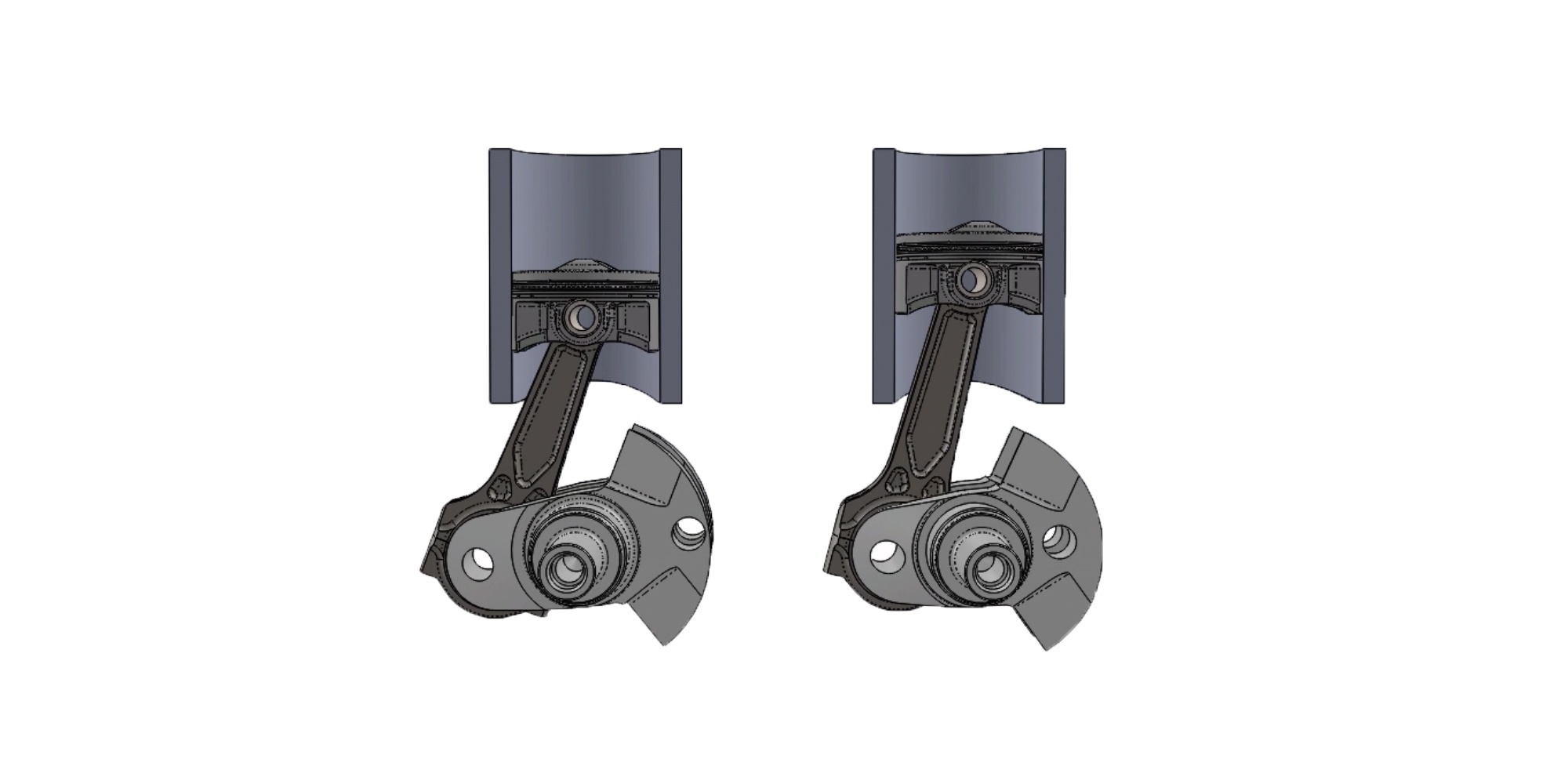
The video above shows two engines, one with a short stroke crankshaft, and the other with a considerably longer stroke. Note that both pistons reach top dead center and bottom dead center at the same time, but the piston in the longer stroke engine (left) has to move significantly faster.
“Rather than focus on mean piston speed, look at the effect of inertia force on the piston,” suggests Dave Fussner, head of research and development at K1 Technologies.
Let’s first review the definition of mean piston speed, also called the average piston speed. It’s the effective distance a piston travels in a given unit of time, and it’s usually expressed in feet per minute (fpm) for comparison purposes. The standard mathematical equation is rather basic:
Mean Piston Speed (fpm)=(Stroke x 2 x RPM)/12
There’s a simpler formula, but more on the math later. A piston’s velocity constantly changes as it moves from top dead center (TDC) to bottom dead center (BDC) and back to TDC during one revolution of the crankshaft. At TDC and BDC, the speed is 0 fpm, and at some point during both the downstroke and upstroke it will accelerate to a maximum velocity before decelerating and returning to 0 fpm.
There are formulas to calculate the piston speed at every degree of crankshaft rotation, but that’s usually much more information than needed by most engine builders. Traditionally they look at the average or mean piston speed during the crank rotation, and they possibly will calculate the maximum piston speed.
The mean piston speed takes the total distance the piston travels during one complete crankshaft revolution and multiplies that by the engine RPM. Piston speed obviously increases as the RPM increase, and piston speed also increases as the stroke increases. Let’s look at a quick example.
To view all of K1 Technologies’ Crankshaft offerings, click HERE
A big-block Chevy with a 4.000-inch-stroke crankshaft running at 6,500 rpm has mean piston speed of 4,333 fpm. Let’s review the formula again used to calculate this result. Multiply the stroke times 2 and then multiply that figure by the RPM. That will give you the total number inches the piston traveled in one minute. In this case, the formula is 4 (stroke) x 2 x 6,500 (RPM), which equals 52,000 inches. To read this in feet per minute, divide by 12. Here’s the complete formula:
(4 x 2 x 6,500)/12=4,333 fpm
You can simplify the formula with a little math trick. Divide the numerator and denominator in this equation by 2, and you’ll get the same answer. In other words, multiply the stroke by the RPM, then divide by 6.
(4 x 6,500)/6=4,333 fpm
With this simpler formula, we’ll calculate the mean piston speed with the stroke increased to 4.500 inch.
(4.5 x 6,500)/6=4,875 fpm
As you can see, the mean piston speed increased nearly 13 percent even though the RPM didn’t change.

Again, this is the average speed of the piston over the entire stroke. To calculate the maximum speed a piston reaches during the stroke requires a bit more calculus as well as the connecting rod length and the rod angularity respective to crankshaft position. There are online calculators that will compute the exact piston speed at any given crankshaft rotation, but here’s a basic formula that engine builders have often used that doesn’t require rod length:
Maximum Piston Speed (fpm)=((Stroke x π)/12)x RPM
Let’s calculate the maximum piston speed for our stroker BBC:
((4.5 x 3.1416)/12)x 6,500=7,658 fpm
By converting feet per minute to miles per hour (1 fpm = 0.011364 mph), this piston goes from 0 to 87 mph in about two inches, then and back to zero within the remaining space of a 4.5-inch deep cylinder. Now consider that a BBC piston weighs about 1.3 pounds, and you can get an idea of the tremendous forces placed on the crankshaft, connecting rod and wrist pin—which is why Fussner suggests looking at the inertia force.
“Inertia is the property of matter that causes it to resist any change in its motion,” explains Fussner. “This principle of physics is especially important in the design of pistons for high-performance applications.”
The force of inertia is a function of mass times acceleration, and the magnitude of these forces increases as the square of the engine speed. In other words, if you double the engine speed from 3,000 to 6,000 rpm, the forces acting on the piston don’t double—they quadruple.
“Once started on its way up the cylinder, the piston with its related components attempt to keep going,” reminds Fussner. “Its motion is arrested and immediately reversed only by the action of the connecting rod and the momentum of the crankshaft.”
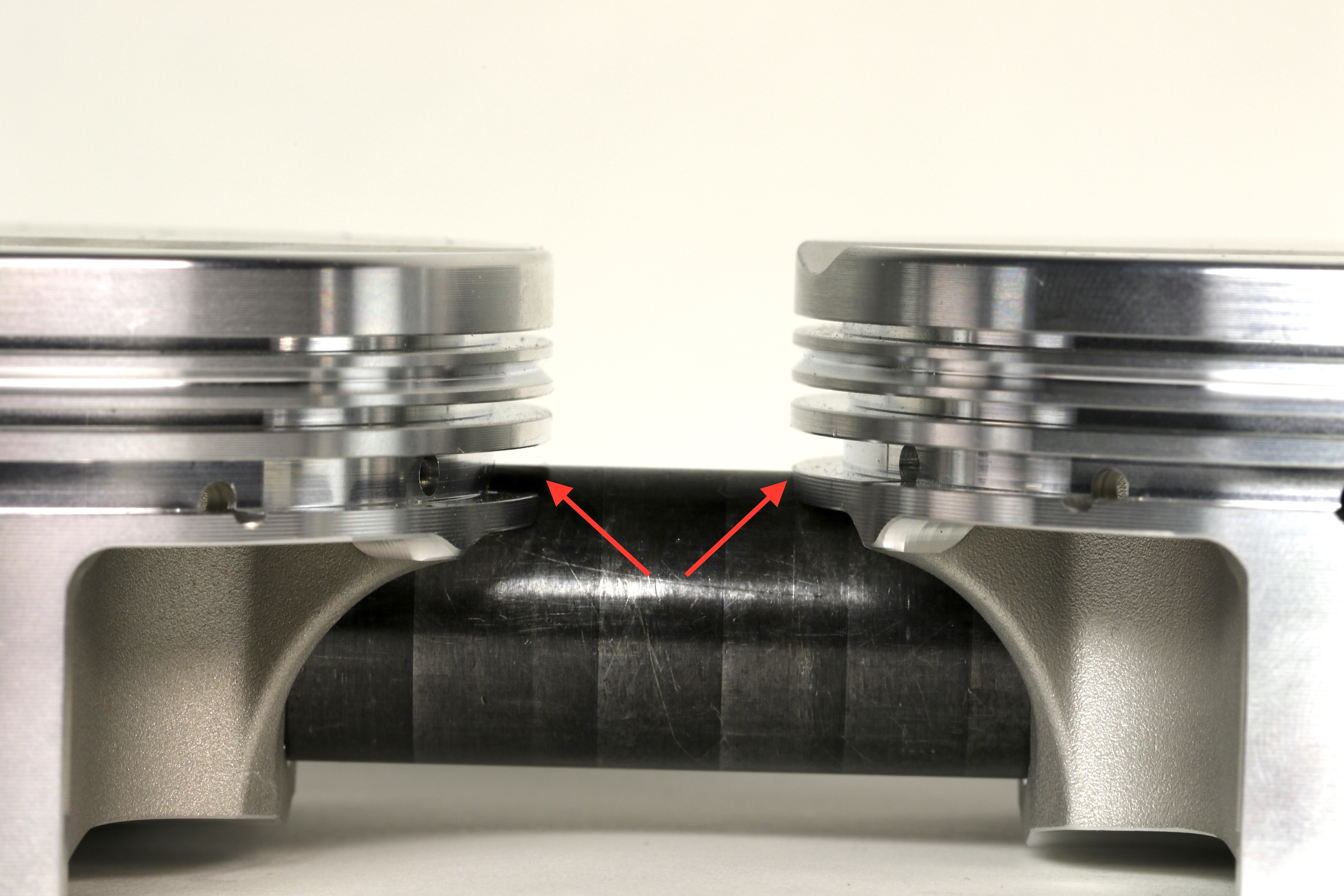
Due to rod angularity—which is affected by connecting rod length and engine stroke—the piston doesn’t reach its maximum upward or downward velocity until about 76 degrees before and after TDC with the exact positions depending on the rod-length-to-stroke ratio,” says Fussner.
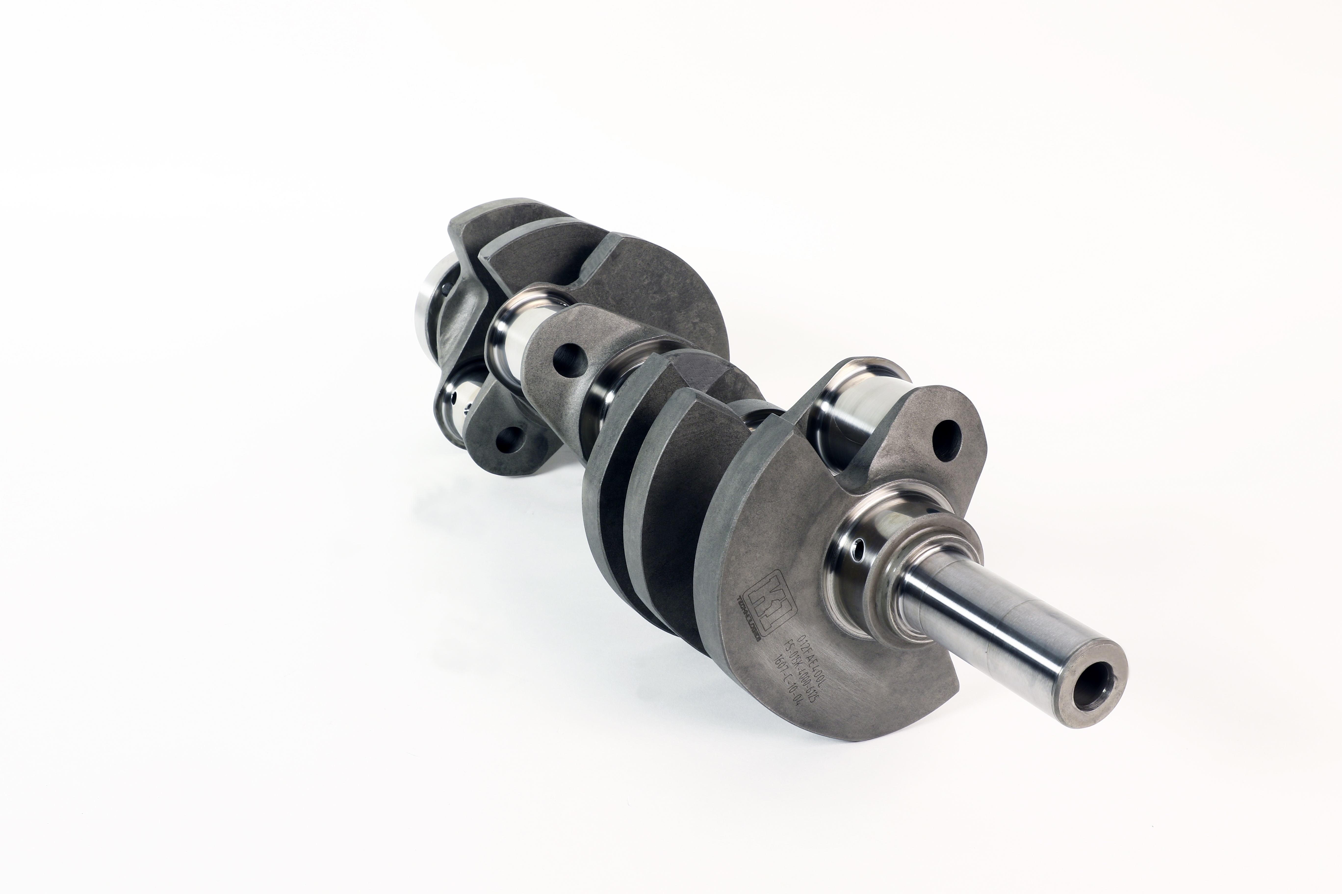 Stroker cranks such as this forged LS7 piece from K1 Technologies, are a great way to add displacement. However, when the stroke is lengthened the piston must accelerate faster each revolution to cover the larger swept area of the cylinder wall. Looking for an LS Stroker crankshaft? Click HERE.
“This means the piston has about 152 degrees of crank rotation to get from maximum speed down to zero and back to maximum speed during the upper half of the stroke. And then about 208 degrees to go through the same sequence during the lower half of the stroke. The upward inertia force is therefore greater than the downward inertia force.”
If you don’t consider the connecting rod, there’s a formula for calculating the primary inertia force:
0.0000142 x Piston Weight (lb) x RPM2 x Stroke (in) = Inertia Force
The piston weight includes the rings, pin and retainers. Let’s look at a simple example of a single-cylinder engine with a 3.000-inch stroke (same as a 283ci and 302ci Chevy small-block) and a 1.000-pound (453.5 grams) piston assembly running at 6,000 rpm:
0.0000142 x 1 x 6,000 x 6,000 x 3 = 1,534 lbs
With some additional math using the rod length and stroke, a correction factor can be obtained to improve the accuracy of the inertia force results.
Crank Radius÷Rod Lenth
“Because of the effect of the connecting rod, the force required to stop and restart the piston is at maximum at TDC,” says Fussner. “The effect of the connecting rod is to increase the primary force at TDC and decrease the primary force at BDC by this R/L factor.”
For this example, the radius is half the crankshaft stroke (1.5 inch) divided by a rod length of 6.000 inches for a factor of .25 or 383 pounds (1,534 x 0.25 = 383). This factor is added to the original inertia force for the upward stroke and subtracted on the downward movement.
“So, the actual upward force at TDC becomes 1,917 pounds and the actual downward force at BDC becomes 1,151 pounds,” says Fussner. “These forces vary in direct proportion to the weight of the piston assembly and the stroke to rod length and they also vary in proportion to the square of the engine speed. Therefore, these figures can be taken as basic ones for easily estimating the forces generated in any other size engine.”
By the way, the mean piston speed for this 1-cylinder engine at 6,000 rpm is 3,000 fpm, and the maximum piston speed (using our previous formula) is 4,712 fpm.
What happens when you increase the stroke from 3.000 inch to 3.250-inch? First, the mean piston speed increases to 3,250 fpm, and the maximum piston speed jumps to 5,105 fpm. Then the primary force increases from 1,534 pounds to 1,661 pounds. There’s also a change when adding in a new R/L factor of .27 (1.625 ÷ 6.000). The actual upward force at TDC becomes 2,109 pounds and the actual downward force at BDC becomes 1,213 pounds.
“If we increase the engine speed with the 3.250-inch stroke to 7,000 rpm, leaving all other details equal, the primary force increases to 2,261 pounds,” says Fussner. “Then apply the R/L factor of .27, and the actual downward force becomes 1,651 pounds. The actual upward force at TDC becomes 2,871 pounds. That’s nearly a ton and a half!”
Now consider the effects of a lighter piston. Keeping the 3.20-inch stroke and 7,000 rpm but going to a piston that weighs 340 grams (.750-pound), the maximum force is reduced from 2,871 pounds to 2,154 pounds, or 717 pounds of less force. This same lighter piston configuration would have a force of 1,238 pounds required to stop and restart the piston at BDC, a reduction of 413 pounds.
“So, with every complete revolution, the engine would see 1,130 pounds less inertia force with the lighter piston assembly,” says Fussner. “This reduction of inertia force would, of course, be applied to each cylinder in a multi-cylinder engine. An engine running 7,000 rpm will stop and start each piston 14,000 times a minute.”
Mean and maximum piston speeds are still valuable calculations for any engine builder making a change to a proven formula. Exceeding 5,000 fpm in mean piston speed should get your attention and prompt rethinking on parts selection. Excessive piston speed can lead to inconsistent lubrication of the cylinder wall, and in some situations the piston will actually accelerate faster than the flame front during combustion. While the former can cause parts failure, the latter is lost horsepower.
And the pistons should also be the lightest possible without sacrificing the required strength and durability. The inertia forces will stretch connecting rods and resist crankshaft acceleration—again potentially leading to parts failure and choking horsepower.
“We know a common measure used for many years to suggest the structural integrity danger zone of a piston in a running engine is mean piston speed,” sums up Fussner. “As the skydive instructor told his student, it’s not the speed of the fall that hurts, it’s the sudden stop. And so it is with pistons. So rather than focus only on the mean piston speed, let’s decide to also consider the effect of inertia force on the piston, and what we can do to reduce that force. And if that is not possible, make sure the components are strong enough to endure the task we have set forth.”
“While increasing the rod length will soften the inertia loading by changing the afore mentioned R/L ratio, it will not reduce the mean piston speed because as long as the stroke is not changed,” continues Fussner. “The piston still must travel the same distance in one revolution of the crankshaft, regardless of the rod length. Speed is distance traveled per unit time.”
A final note on piston speed—, 2,500 fpm was considered the upper limit for piston speed not too long ago. It is important to consider that mean piston speed is also used as guide for considering other engine components, such as connecting rods and crankshafts. In the early days of hot rodding, most engines had cast iron cranks and rods and cast aluminum pistons, which are not nearly as strong as engine parts today.
“So, adding strength to these parts has allowed the safe mean piston speed to more than double to 5,000 fpm or more,” says Fussner. “Another factor is the usage. Will the engine be operated for extended periods at high piston speed, or for a quick pass down the drag strip? Reducing the exposure time at high piston speeds increases reliability. Strong, light components will be able to endure higher pistons speeds than heavy lower strength components.”