Quench: Unlocking Performance Squished Between the Piston and Head
When you are building an engine, and you are trying to get the most possible power out of it, you start looking into different areas of optimization. One area that can be optimized in a number of ways, is the quench area. You can change combustion chamber designs, piston designs, and even head-gasket-thickness to adjust an engine’s quench area. However, before you can consider the pros and cons of different configurations and designs, you have to understand not only what it is, but what it does in the combustion process, and how that can help or hurt your end goal.
What is Quench?
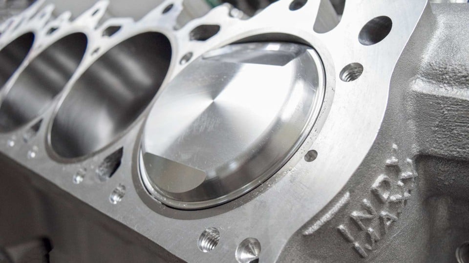
Quench is the distance between the piston and cylinder head when the piston is at top dead center (TDC). Ultimately it can be thought of as piston to head clearance. The distance includes the piston to deck clearance and head gasket compressed thickness. Sometimes referred to as squish, quench is responsible for forcing the air-fuel mixture into the combustion chamber area near the spark plug.
Along with the obvious advantage of moving the air-fuel mixture toward the source of ignition, quench also reduces rich-lean spots, averages chamber temperatures, and accelerates flame propagation. Each of these improve efficiency, longevity, and overall engine performance. Therefore, quench area is certainly an important piece of engine design.
What are the Advantages of Quench Area in the Combustion Chamber?
If you think of quench as squishing the air-fuel mixture, it is easier to visualize the effect quench area has on the mixture itself. Imagine a puddle of water on the sidewalk as a young child in new rain boots leaps towards it. As the water gets squished between the excited child’s boots and the sidewalk, it moves rapidly outward creating a splash.
The water droplets that were puddled together are suddenly forced to separate and mix with the air above them. They accelerate from standing still to moving outward at a high velocity. Turbulence is created in both the air around the puddle and within the puddle itself. Now, transfer that visualization into the engine cylinder and the advantages of quench become clearer.
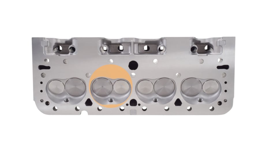
Quench area is highlighted on this wedge chambered head. This is where air-fuel would be squished between the piston and cylinder head.
Reduces Rich-Lean Spots
An important aspect of intake runner design, especially in carbureted and throttle-body injection applications, is to keep the fuel suspended in the air stream as it approaches the cylinder. Air velocity is key in keeping fuel from dropping out of the air stream. However, the air-fuel mix quickly decelerates as it enters the increased area of the cylinder. The heavy fuel droplets fall out of the air stream and pool together.
Quench is responsible for introducing velocity back into the mixture. A tighter quench will obtain more velocity as it forces the mixture into the combustion chamber. Going back to the illustration of jumping into a puddle of water, tightening quench would be like increasing the boot size from toddler to men’s size 13.
“The higher velocity results in more of the mixture being ‘mixed’ and a higher percent of the A/F can be burned,” explains Mike Hupertz, testing and R&D engineer at Cometic Gaskets. “Now with this velocity there is turbulence. We know turbulence is less than ideal in the induction system, but we want to see as much turbulence as we can get in the combustion process. The more turbulence experienced while the piston is ascending to TDC, the more homogenous the A/F mixture becomes — resulting in a more efficient burn, basically more power with less unburned A/F.”
In other words, quench effectively reduces rich-lean spots. Temperatures in the combustion chamber are consequently averaged out. That means less chance for detonation and more consistent burn rates from cycle to cycle.
Accelerates Flame Propagation
The added velocity created by quench causes turbulence inside the combustion chamber. The result is a well-mixed dose of air and fuel. A consistent air-fuel ratio within the chamber offers more efficient combustion. In addition, the burn rate of the mixture is also affected.
Two separate processes occur during combustion. First is the most obvious and probably what comes to mind as you visualize the combustion process. Heat created by the ignition source, a spark plug in this case, raises the temperature of nearby fuel molecules to the point of combustion. As fuel combines with oxygen molecules during combustion, additional heat is produced, thereby starting a chain reaction, heating other adjacent fuel molecules to the point of combustion. This continues until the mixture is completely burned or is not able to effectively combust.
A second process is not as apparent. As temperature rises from the burning fuel molecules, pressure increases in that area resulting in a compression wave. The compression wave assists in spreading the flame but may also be responsible for detonation if too great for the fuel being used. These two processes are responsible for moving the flame front across the combustion chamber. This flame travel is referred to as flame propagation.
In order to have maximum cylinder pressure occur slightly after TDC, the ignition process must start as the piston is still ascending upward. That means pressure inside the combustion chamber is working against the piston for some period. Accelerating flame propagation allows for less ignition timing advance, and therefore reduces the amount of time combustion pressure is working against engine rotation.
Quench accelerates flame propagation in a couple of ways, both related to turbulence. First the homogenous mixture created from turbulence will burn more consistently. Lean mixtures have a slower burn rate than rich ones, and a perfect mix will burn the fastest. Reducing reach-lean spots in the chamber allows for consistent burn rates from power cycle to power cycle, and more precise ignition timing from one cylinder to the next. Second, turbulence itself accelerates flame propagation substantially, and it does so at or near TDC, again reducing the timing advance required.
Limitations and Considerations: How Much Quench Should I Run?
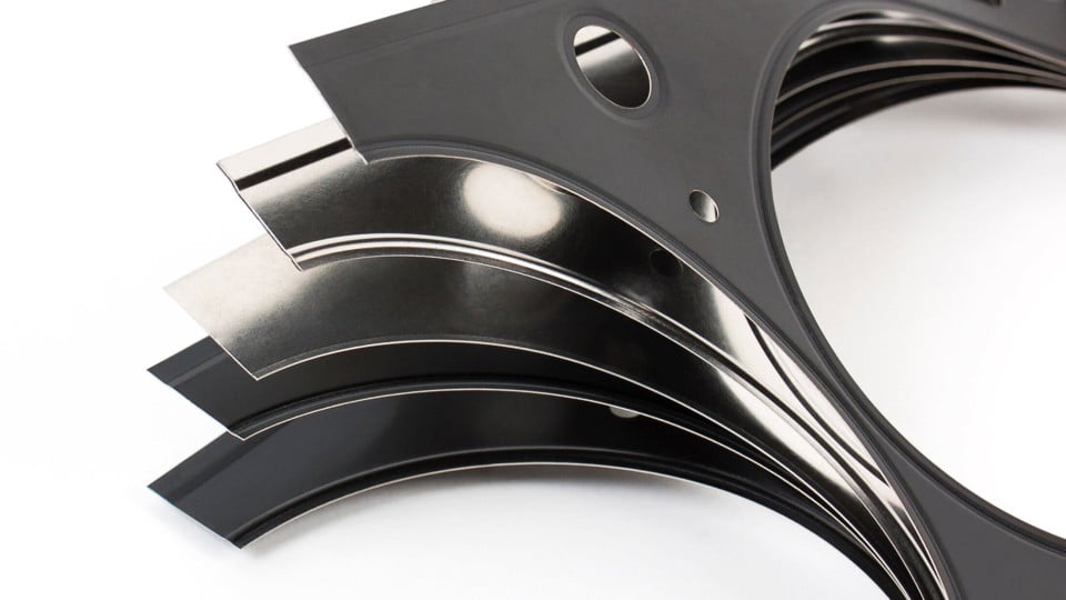
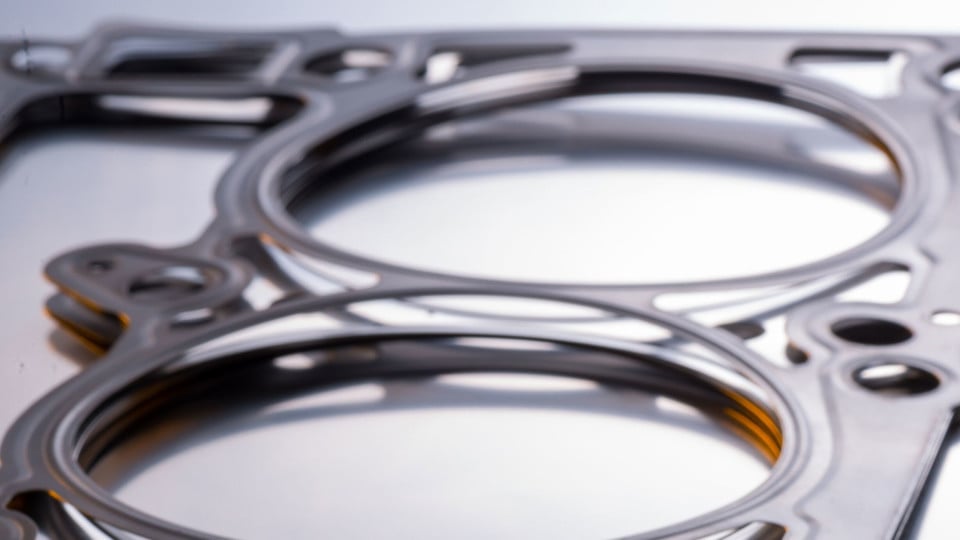
“We want the quench to be as tight as mechanically possible for the engine design.” That is the recommendation of Cometic’s testing engineer, Mike Hupertz. Cometic makes adjusting the quench area easy using their MLS (Multi-Layered Steel) head gaskets. These gaskets are comprised of a stainless-steel shim, available in various thicknesses, sandwiched between embossed and coated outer layers.
Engine Application Limitations
Although quench should be as tight as possible, there are limitations. Hupertz outlines some of the considerations that go into determining the ideal quench for specific engine designs:
“There are a host of things to consider when setting the quench distance: What is the intended use of the engine? Are there power-adders like nitrous oxide or a turbocharger? What is the maximum RPM the engine will see? Is the connecting rod material steel, aluminum, or titanium? How much piston rock is there at TDC?” asks Hupertz. “All of these have a direct effect on the piston to head distance. There are compromises that should be considered. For instance, a high-RPM, aluminum-rod, nitrous engine will need additional clearance that will not have ideal quench for a complete burn, but is a must if you want the engine to live and not self-destruct.”
Standard head gaskets typically have a compressed thickness around .040-inches. That works well for stock and most street performance builds if the piston is even with or slightly below the deck at TDC. If the rotating assembly height is taller than the deck height, the piston will protrude past the deck surface and may require a thicker gasket to give adequate clearance.
Quench should never be less than .035-inches. As Hupertz points out, the quench distance should be increased if the piston has enough rock at TDC to protrude above the deck. High RPM and aluminum connecting rod applications will require additional clearance as well due to their expansion at operating temperatures and high speeds.
Combustion Chamber Volume and Design Considerations
Combustion chamber volume and its overall design should also be considered. Chamber volume is the major component in determining static compression ratios. Situations where quench must be sacrificed in order to keep compression in check to satisfy a competition rule or accommodate existing parts, do arise. Increasing head gasket thickness is an easy and affordable way to reduce compression. However, reducing quench will also reduce efficiency and lessen resistance to detonation.
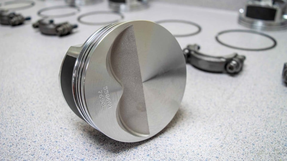
Overall design of the combustion chamber will determine how great the effect of reducing quench will be. Overall design includes the chamber area in the cylinder head as well as the piston which makes up the lower portion of the combustion chamber. Quench is most effective with wedge chambers and flat-top pistons. Consequently, it is logical to see a greater effect on engine performance and timing requirements when adjusting quench. Stepped-dish and full-dish piston designs reduce the area available to provide adequate quench.
Chambers that require a domed piston like hemispherical designs have very little quench. The result is a slow-burning chamber that requires more total ignition timing. However, the high breathing capabilities of a Hemi will outweigh that disadvantage. Fast-burn Pentroof designs are more common in modern engines. This becomes the best design in terms of burn-rate and flame propagation when quench is introduced.
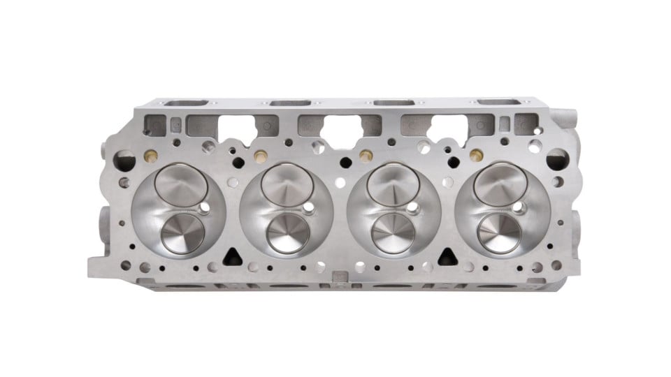
Hemispherical combustion chambers have very little area to introduce quench, leading to a slow-burning flame front which requires increased timing.
The advancement in 3-D profiling and CNC machining allows for precise designs that OEM and aftermarket manufacturers use to maximize efficiency by allowing cylinder head combustion chambers and pistons to work together more effectively. Some aftermarket piston companies offer this level of design for custom builds, but that may be outside the budget of most performance enthusiasts. Understanding the advantages of quench, and the limitations specific engine applications may have on it, will provide enough insight for most to make educated decisions on head gasket thickness and overall chamber design for their given build.


