
MAY 18, 2021
The world of high-performance engines is heating up. Average horsepower and engine RPM are on the ascent. Along with this newfound power are new demands placed on the most highly stressed engine component in any engine — the connecting rod bolts.
Think about the force exerted on a pair of rod bolts when the piston and rod assembly has to change direction at 7,000 or 8,000 rpm at the top of its stroke. When this change in direction occurs, the crankshaft yanks very hard on the connecting rod and piston. This action tries to separate the rod cap from the rod with thousands of pounds of force. The only thing preventing this is a small pair of high-strength rod bolts. This makes the material, the method in which these pieces are made, and how they are installed critical, as they are the most important fasteners in any engine.
Toward this end, Automotive Racing Products (ARP) has created a line of rod bolts made of various alloys of steel, intended to cover a wide range of high-performance applications. Making life easier is that each tier of bolts is identified by its alloy’s name. There are multiple ways to classify the strength of a fastener. Each of these terms is defined in the accompanying chart. We placed these definitions in the chart so they will be easy to find as you may likely need to refer to these several times in order to understand the complex relationships surrounding a fastener’s ability to withstand a load and its capacity to create a given clamp load.
Material Strength Definitions
Tensile Strength – (Ultimate Tensile Strength – UTS) – the maximum stress a material can support without breaking, expressed in pounds per square inch or psi. The term stress would be a load applied that applies a stretching force that is attempting to pull the bolt apart.
Yield Strength – the stress applied to the material that causes the material to begin to permanently deform – something engineers call plastic deformation. Beyond this point is where the deforming material will begin to fail.
Fatigue Strength – The ASTM defines it as a limiting value of stress after which failure will occur after a given number of cycles of load have been applied. The cycle count will depend upon the strength of the material as well as the load and the number of cycles applied.
Clamp Load – the amount of load applied to a fastener that will create tension on the fastener. Ideally, this load is a major percentage of the fastener’s yield strength. As the tightening load is increased (but still below the yield point), the clamp load will also increase.
Toughness – Toughness is the material’s ability to absorb energy before ultimate failure. Stated another way, toughness can be measured by the energy required to fracture the material.
Strength – a measure of the maximum stress a material can withstand before beginning to fracture.
A Threaded Spring
The classic way to describe a fastener is to think of it as a spring. As you tighten a bolt, it will begin to stretch. If you over-tighten it, the bolt will pull apart like a piece of taffy that’s been left in the sun, which will eventually lead to it breaking apart. The amount of force required to cause the fastener to fail depends on its material and how the fastener was constructed.
For example, ARP makes all its rod bolts by first starting with the highest quality material in rod form, and then creating the basic bolt shape. Once it is shaped, it is then subjected to a careful heat-treating process and then the threads are formed by squeezing the fastener between two dies that roll rather than cut the threads. By rolling the threads after heat treating (instead of before heat-treat) it creates a far stronger grain pattern. This makes it more difficult to form the threads and is harder on the thread rolling equipment but ultimately creates a higher quality rod bolt.
Ultimate tensile strength is often used as the measuring stick for bolt performance, but it is not the only judge of how well a rod bolt will perform. A higher tensile strength allows the bolt to be tightened more to create a stronger connection, but ultimately bolt performance in an engine is more closely tied to the fastener’s yield strength. This is really the factor that determines the amount of clamp load that can be applied to the bolt to retain the cap on the rod.
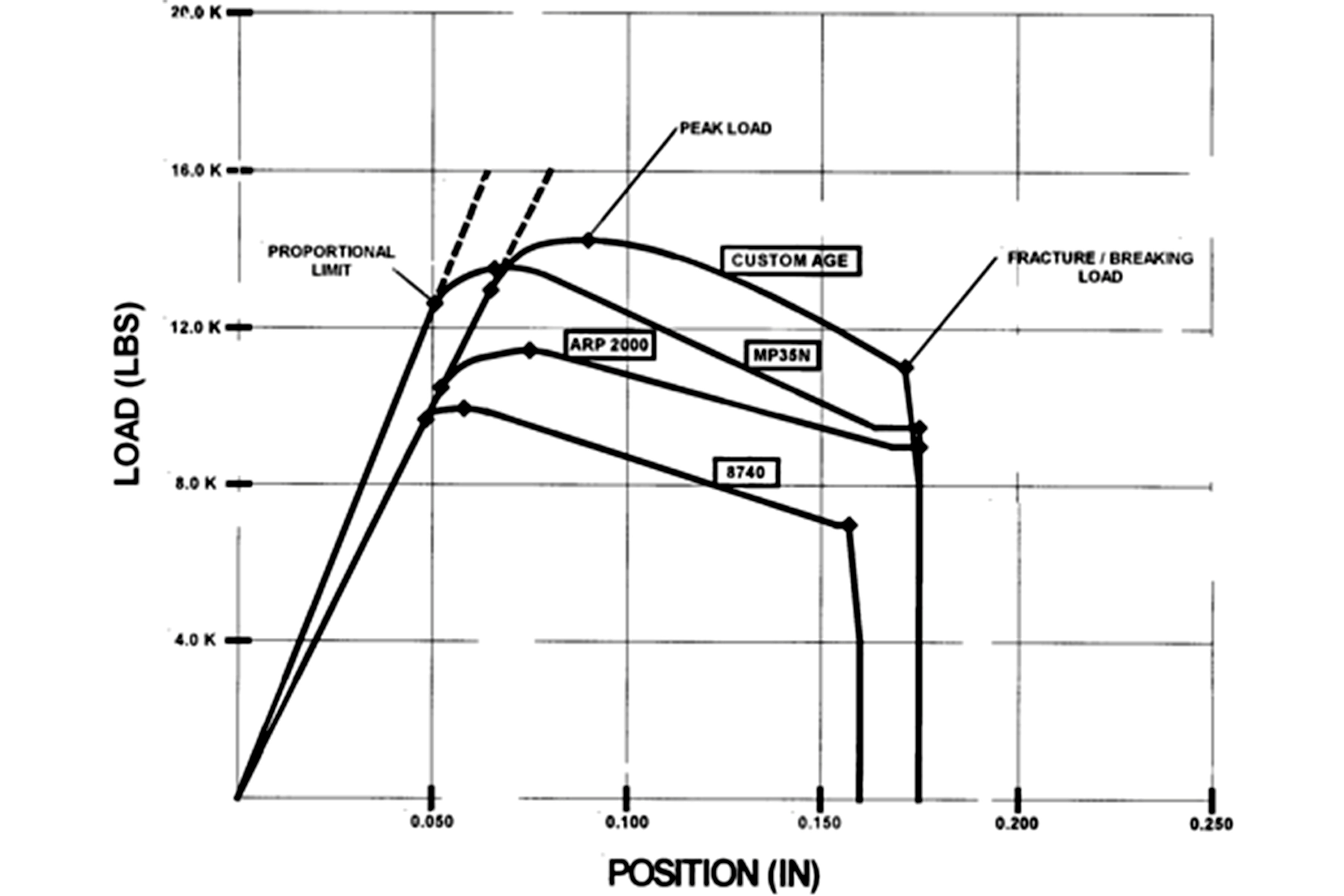
This is a graph created by ARP engineer Chris Brown that shows a strain curve for each of the ARP 8740, ARP 200, MP34N material, and the Custom Age 625. The proportional limit for each of these bolts is essentially the yield point of the fastener. ARP sets the stretch limit for its rod bolts at roughly 75-percent of the yield point. This creates an additional safety factor while still achieving the intended clamp load. Brown also points out that the “stretch” numbers across the X or bottom axis are off by a factor of 10. The number actually represents the movement of the fixture on the tensile test rig and not the actual bolt stretch numbers.
The ability of the fastener to withstand bending forces, often referred to as ductility, is another critical element. There are always bending forces present in connecting rods due to the cyclical forces created by the rotating mass. Generally speaking, as the ultimate tensile strength and yield strength increase, the higher quality material exhibits improved ductility. This can be seen in the wider spread between the tensile strength and the yield strength. This is not always the case with higher-strength materials, however.
Fatigue strength is another important component of a rod bolt and, while it is related to ultimate tensile strength, it is a separate evaluation. For example, the fastener could have very high tensile strength but it might be easily fatigued. In that situation, the bolt could fail after only a low number of load cycles. This, then, would not be a good material to use for a rod bolt.
Clamp load is defined as the amount of tension created to retain the rod cap on the rod. The clamp load must be sufficient to withstand the force generated by reciprocating weight and RPM that attempts to separate the cap from the rod. The size and tensile strength of the rod bolt needs to be sufficient to exceed the force that’s trying to separate the rod cap from the rod. This makes clamp load directly related to ultimate tensile strength.
Material Strength Ratings
| Bolt Material | Tensile Strength (PSI) | Yeild Strength (PSI) |
| ARP 8740 | 190,000 | 180,000 |
| ARP 2000 | 220,000 | 200,000 |
| L19 | 260,000 | 200,000 – 230,000 |
| ARP 3.5 | 220,000-250,000 | 260,000-280,000 |
| ARP Custom Age 625 | 260,000-280,000 | 235,000-255,000 |
Putting All Those Figures Together
It might appear that the best move would be to use the highest quality rod bolt for even the most common engine build, but that would be like using $20 per gallon race gas to power your lawn tractor. While the high-quality components are good at what they do, it’s not the best use of limited funds while offering only limited advantages. Estimating when it would be better to use an ARP 3.5 bolt over an ARP 2000 can be a complex question with no simple answers due to the number of variables.
The standard consideration for choosing a high-performance rod bolt often looks at engine speed as a consideration when evaluating the strength of a rod bolt. The reality is that there are many more factors besides the engine speed, including the reciprocating weight of the piston and rod, as well as connecting rod design factors, and a host of other variables. The reason that RPM is so important is illustrated in the ARP catalog with an equation where the force created by the reciprocating weight is multiplied by the square of engine RPM.
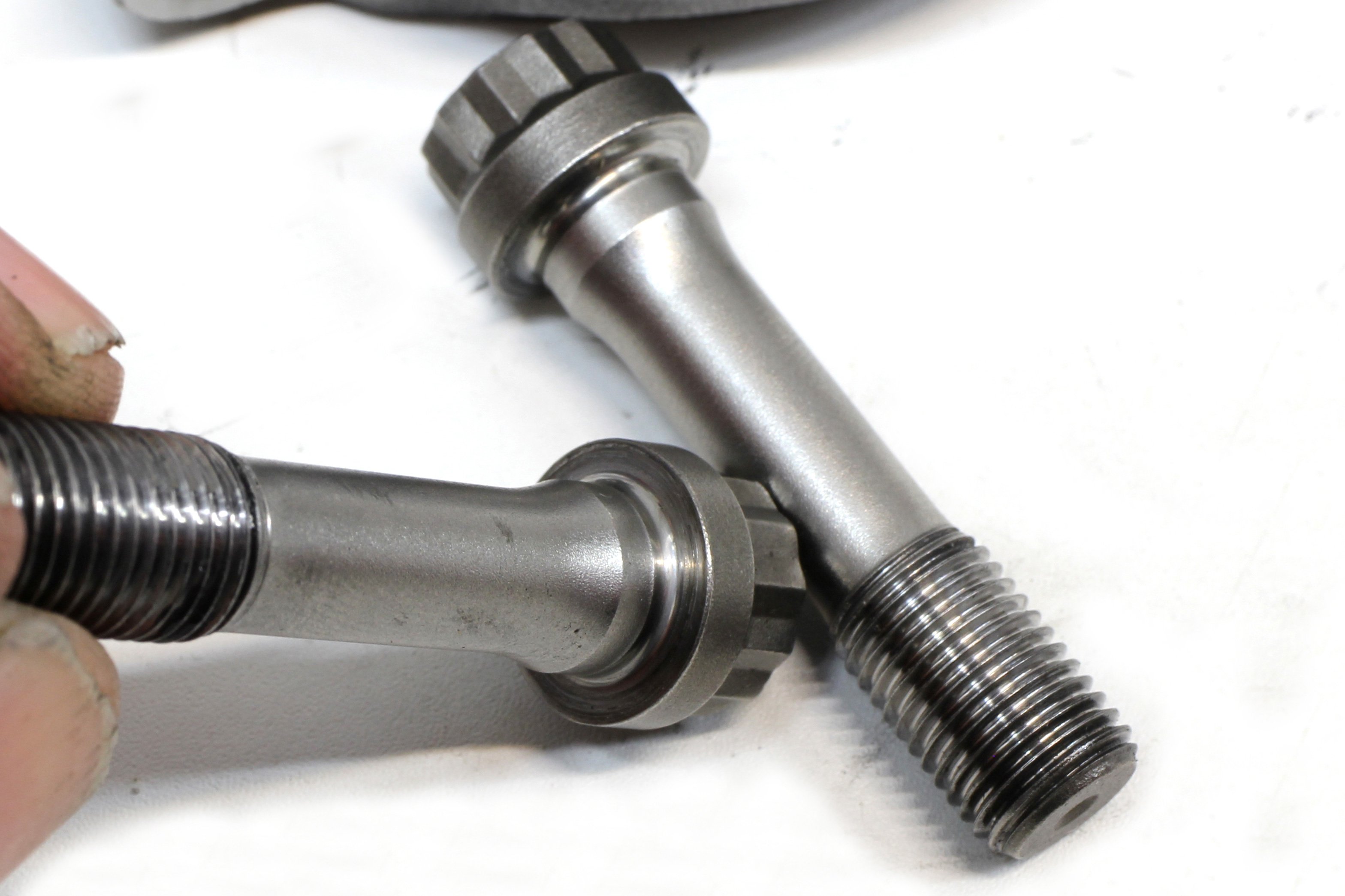
Among the critical points on any rod bolt is the radius underneath the bolt head. This is where the rod bolt’s maximum stress will be concentrated. A sharp corner will create stress risers that can quickly fail the bolt. A properly designed radius greatly increases the bolt’s overall ability to withstand a high-tensile load.
This makes it clear then that doubling the engine speed from 4,000 to 8,000 rpm would increase the force that pulls the rod cap off, generated across top dead center, by a factor of four. So doubling the speed would quadruple the force on the rod bolts. ARP’s approach is to calculate the load for a particular rotating assembly with one fastener and then use two that would safely retain the load. This offers a very secure safety margin.
This is why ARP recommends that if you have an atypical application for a rod bolt, it is best to call their technical department for guidance rather than merely choose a fastener based on a vague knowledge of metallurgy or a magazine story. It’s better to let the professionals calculate the best fastener material for that application.
The best way to ensure that the rod bolt creates the optimal clamp load is to tighten the bolt to ARP’s recommended stretch limit. This not only creates the ideal clamp load but also allows the bolt to be reused multiple times since the stretch spec is just below the bolt’s yield point. Unfortunately, many bolts require using fastener torque to estimate stretch, as opposed to actually measuring stretch itself.
The Key Parameters
Much of the discussion in this story revolves around tensile strength and the yield point. The rule of thumb for fasteners is that the yield point occurs at 90-percent of the ultimate tensile strength. According to Jay Combes at ARP, this ratio will change depending upon the alloy. You can see this effect in the ARP illustration between the yield point and the peak of the curve.
Returning to the bolt-as-a-spring analogy, the ideal situation is to tighten the fastener to a point just below the bolt’s yield point. This is just like stretching a spring to its normal extension. When the load is relaxed, the spring returns to its normal relaxed length. If we over-stretch the spring, the metal deforms (what the metallurgists call plastic deformation). Once that occurs, the spring is permanently damaged and will eventually fail where the deformation took place.
The same situation occurs with a rod bolt. The best way to create the ideal tension and clamp load on the connecting rod cap is by tightening the bolt so that it does not exceed its clamp load. ARP creates a stretch number to achieve that load while still offering a safety margin that does not exceed the yield point of the fastener.
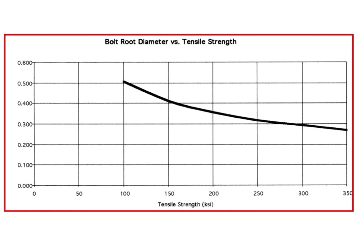
The ARP chart shows the relationship of the thread root (minimum) diameter of the bolt versus tensile strength as measured in “ksi” which is kilo-pound force per square inch. 1 ksi = 1,000 psi. In this example, a 0.400-inch root diameter requires a 150, ksi rating while a bolt with a 300 ksi rating only requires a root diameter bolt of 0.300-inch. In other words, a stronger material allows the use of a smaller bolt with no loss of strength. This is the benefit of using a stronger bolt.
By creating this maximum clamp load on the rod cap, it holds the rod cap in place under all of the loads acting on it. In the past when loads were not as severe as today, this clamp load was established by torquing the rod bolt in place. The ideal torque value is generated through an estimate of the friction necessary to tighten the fastener enough to achieve the desired amount of stretch imparted into the fastener. If the torque value is too low, the clamp load is insufficient and the rod cap itself will fail. If the torque load is excessive, this stretches the bolt past its yield point, which is almost guaranteed to cause the bolt to fail.
With so many variables present when applying torque to establish the proper load on the bolt, the best way to establish the proper tension on the bolt is to use a stretch gauge. Through testing for a given diameter, design, and length of the rod bolt, ARP will create a specific stretch value for that bolt. The design of the bolt plays a big part in stretch since the length of the undercut in relation to the under-head length will affect this stretch value as well as the material.
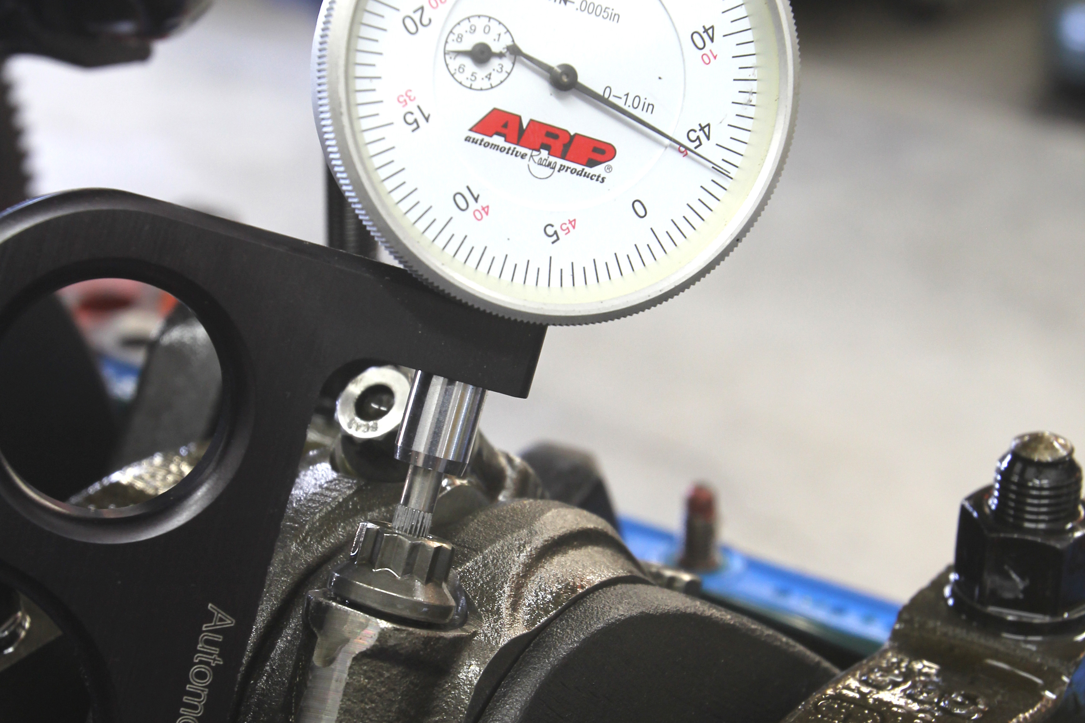
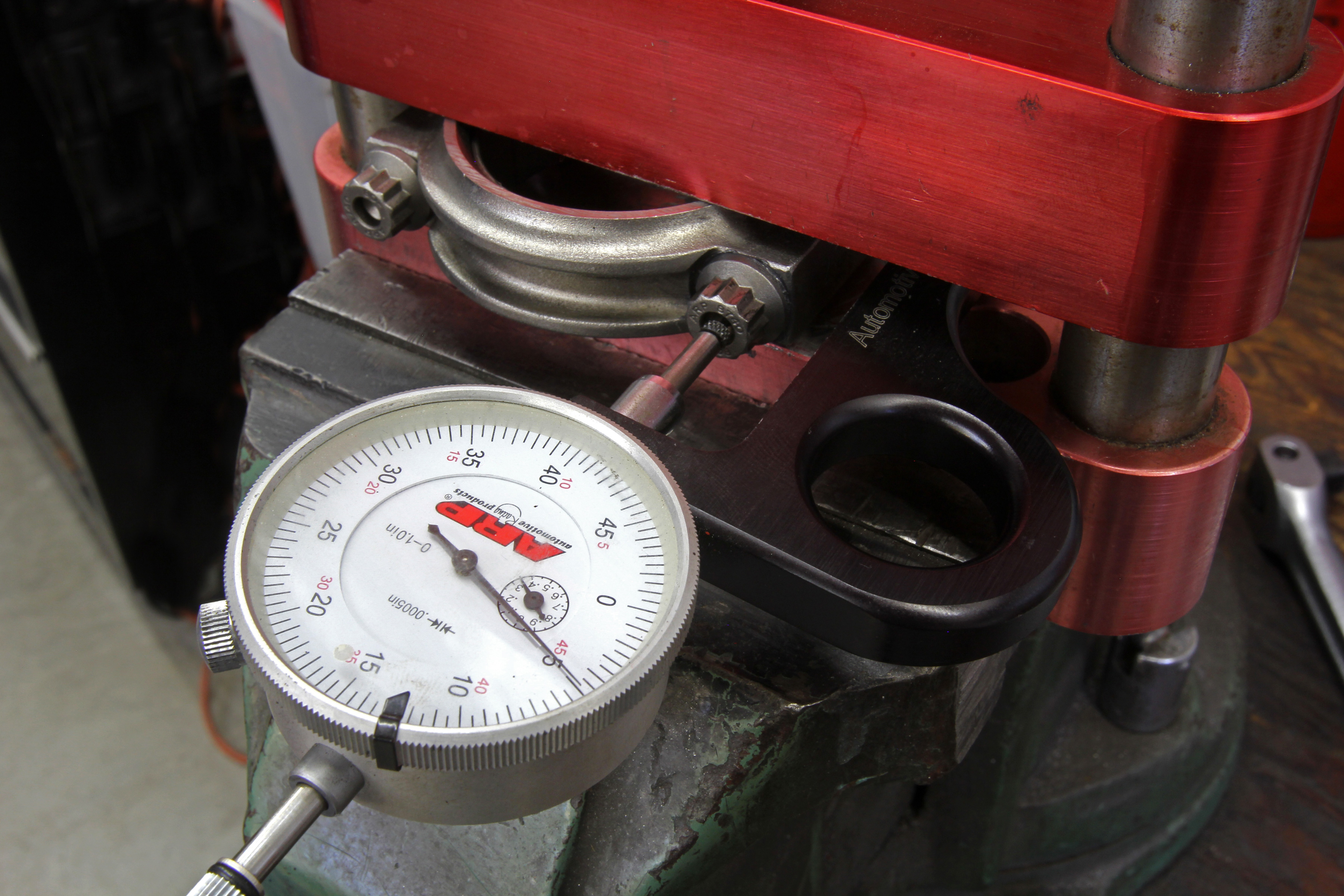
We experimented with an ARP big-block rod bolt by applying torque to the required specs of 55 ft-lbs using engine oil as a lubricant. We then zeroed our stretch gauge and loosened the rod bolt. As you can see, the bolt stretch was only slightly more than 0.004-inch. The ideal stretch for this bolt is 0.0055 to 0.006-inch. This illustrates why using a stretch gauge is far more accurate, creating an optimal clamp load.
As an example, let’s take a 3/8-inch ARP 8740 rod bolt for a big-block connecting rod. The bolt, in this case, is P/N 135-6002 where ARP specifies a rod bolt stretch figure of 0.0055 to 0.0060-inch. If we wanted to upgrade to a stronger ARP Pro Wave 2000 bolt for this application, the different material bolt requires a different stretch value. In this case, that would be 0.0065 to 0.0070-inch. This would create a much higher clamp load to withstand a greater tensile loading.
There is much more to the metallurgy and design of even the entry-level 8740 ARP rod bolt than we can cover in this short story. Perhaps the most important point worth repeating is that even the best-designed and machined fasteners can still fail if not installed correctly. So once you’ve decided on the best bolt for the engine, it’s critical that these be installed correctly. The combination of a high-quality bolt installed properly is the best insurance policy you could write up for your engine.