
MARCH 18, 2021
“Run a dingle-ball hone through it, throw in a new set of rings — and you’re ready to go.”
Not long ago, this might have been considered an acceptable practice for a mild street engine. While this may still be the approach for the backyard engine builder, 21st Century internal combustion engines have progressed to the point where attention to detail can pay off with less internal friction, more horsepower and torque, less blow-by, and even superior oil control.
Among all the attention paid to piston rings, far too little has been addressed to the oil rings. But within the trio of the three-ring piston, more friction is generated by the oil ring package than the sum of the other two rings combined. So perhaps we should start with some technical details that may be surprising. One approach to improve power and efficiency on any engine would be to reduce the friction of a typical oil ring while not compromising oil control. Let’s start by addressing what is commonly referred to as standard tension oil rings.
It’s not unusual for the ends of an oil ring expander to not touch when placed in the bore. However, when placed in the piston groove and the oil rings are installed, the rings press on the expander and create the necessary tension. According to Keith Jones, there is little to be gained by adjusting the ends by bending them inward.
Standard Isn’t So Standard
For street engines, nearly all recommendations call for a “standard” oil ring package and to avoid using “low drag” oil rings because of the risk of allowing too much oil into the combustion chamber.
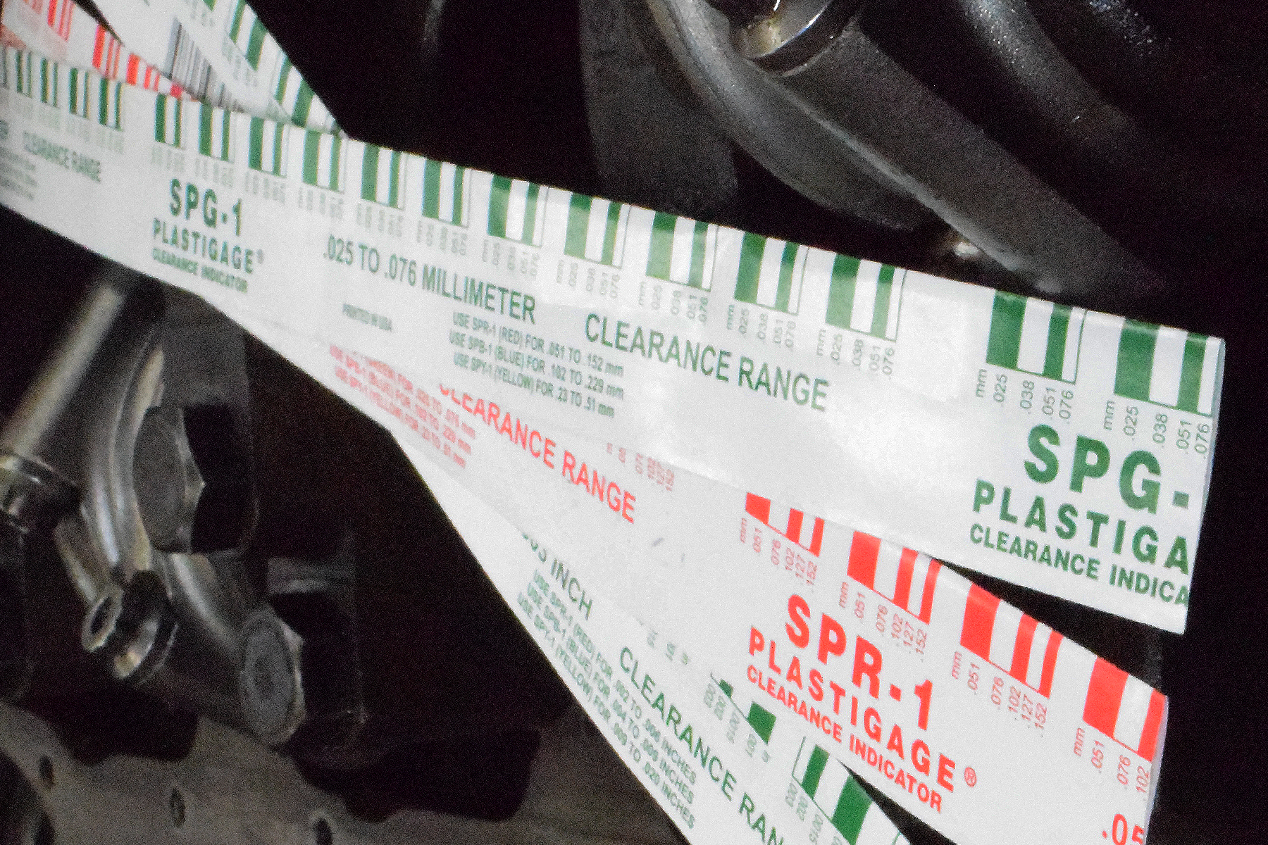
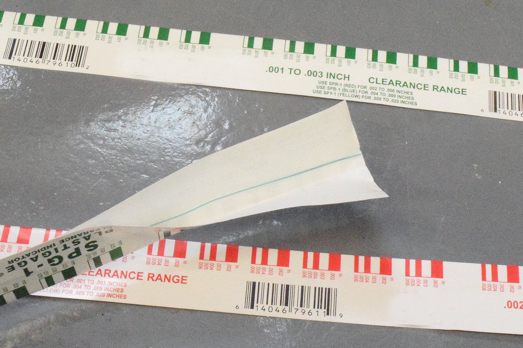
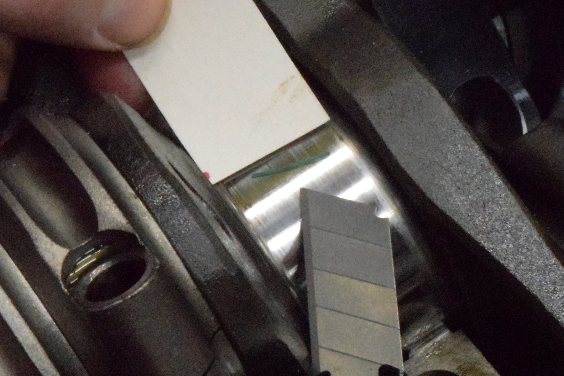
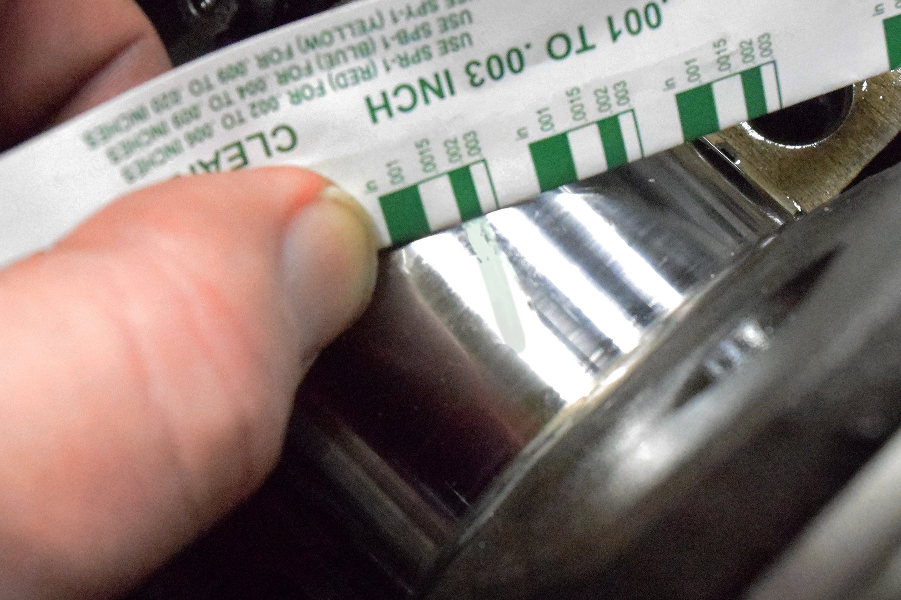
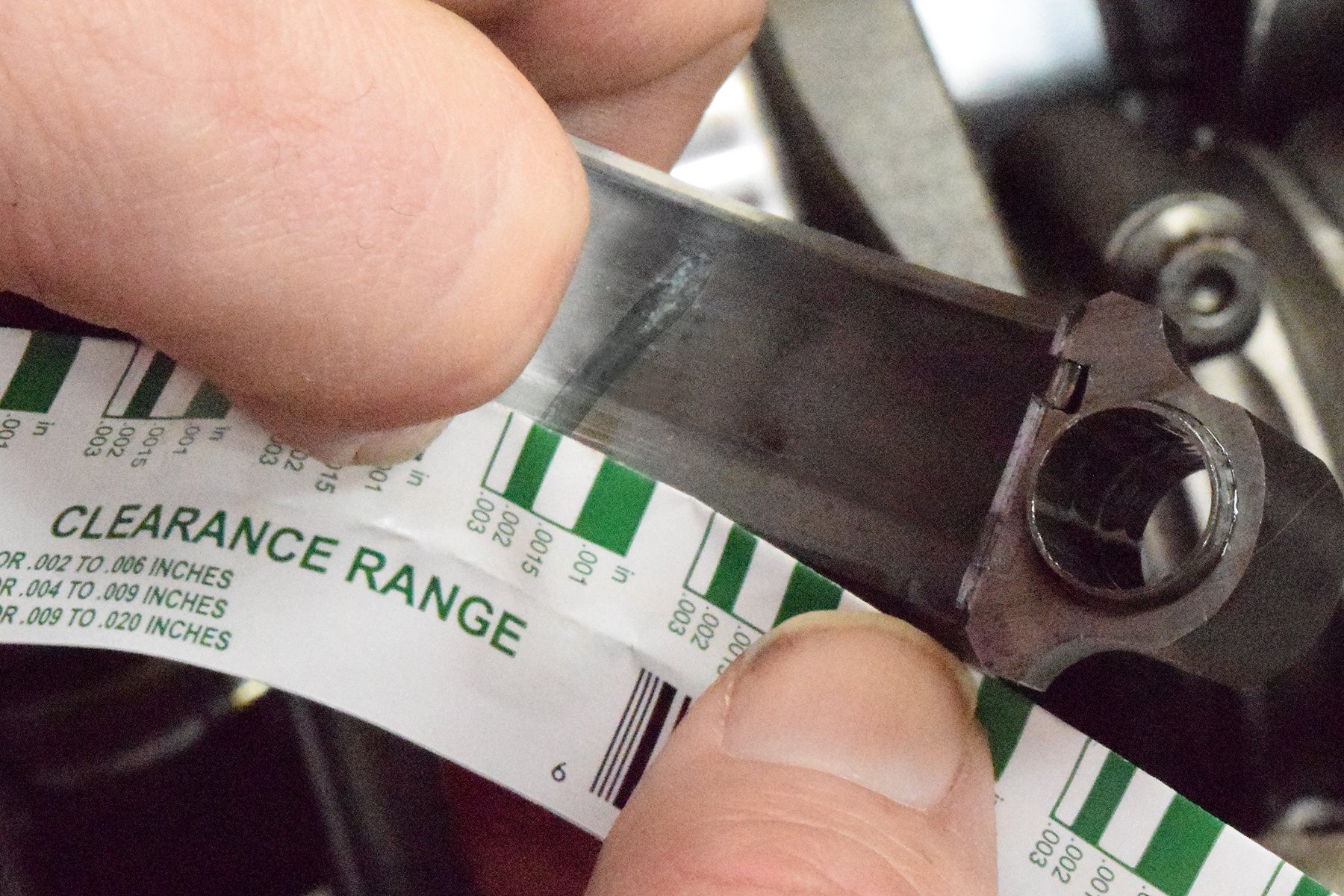
It turns out that what is termed a “standard” tension oil ring is anything but standardized. We’ve included a chart created using data supplied by Total Seal that offers some interesting information. The force listed in the accompanying chart is expressed in pound-force (lbf).
Radial Tension Chart
Loads listed for each ring in this chart are the actual radial (outward) force exerted by the ring. This is not the amount of friction generated by the movement of the piston in the bore. This is an important distinction that should not be overlooked.
| Ring Pack | Oil Ring | Radial Tension
(lb-force) |
Improvement |
| Standard | 3/16 (0.187”) | 20 | — |
| Standard | 3.0mm (0.118”) | 11 | -9 lbf = 45% |
| Ultra-Thin | 2.0mm (0.078”) | 8.0 | -12 lbf = 60% |
This is not lb-ft or torque, which is a twisting motion. Pound-force is the radial or outward tension against the cylinder wall created by the oil ring when compressed in the cylinder. These lbf measurements were obtained with a very sophisticated (and expensive — like, $60,000 expensive) tool used by Total Seal to measure this force. These lbf readings do not represent sliding friction, although common sense dictates that higher radial tension will certainly contribute to increased sliding friction.
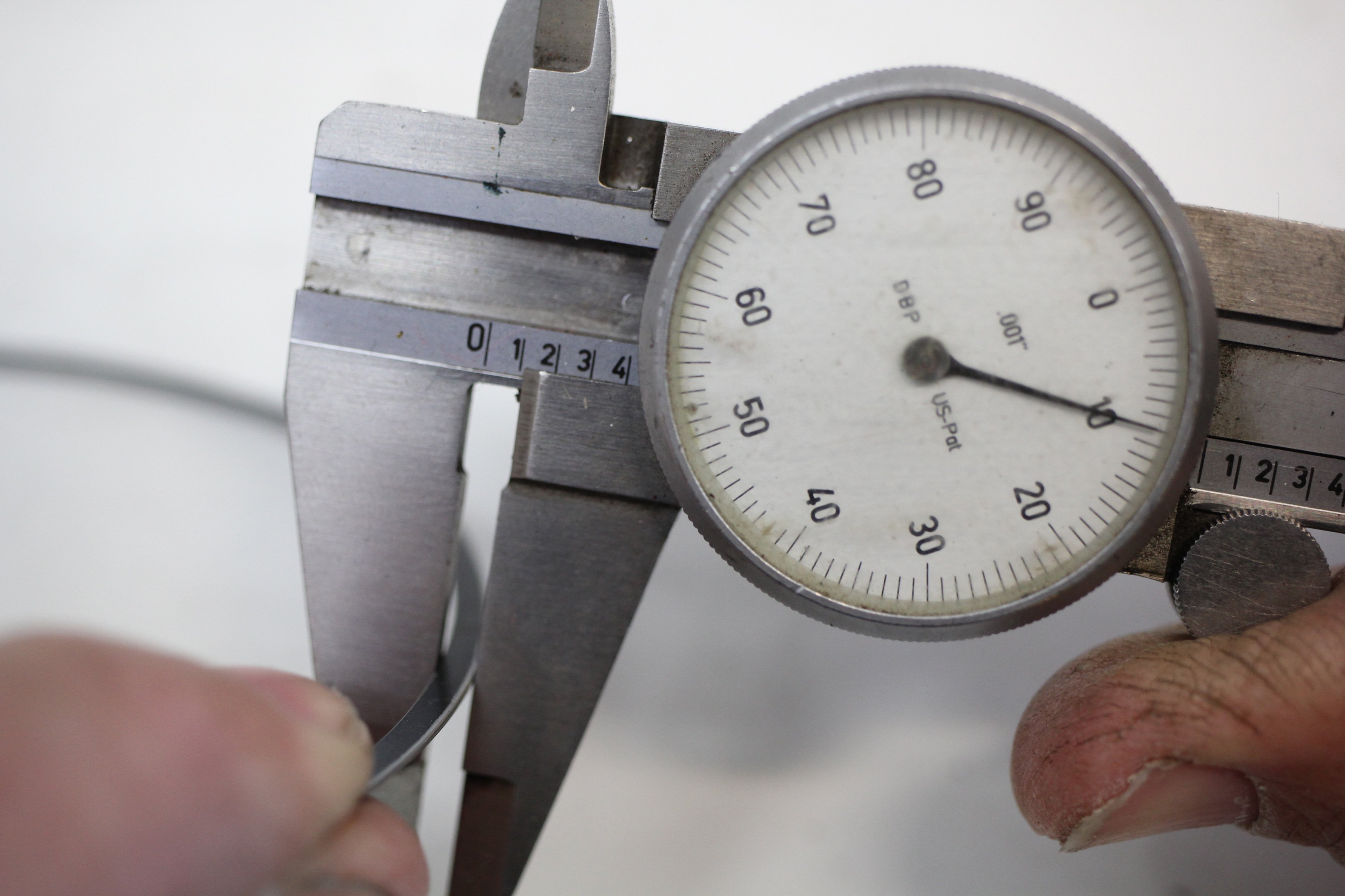
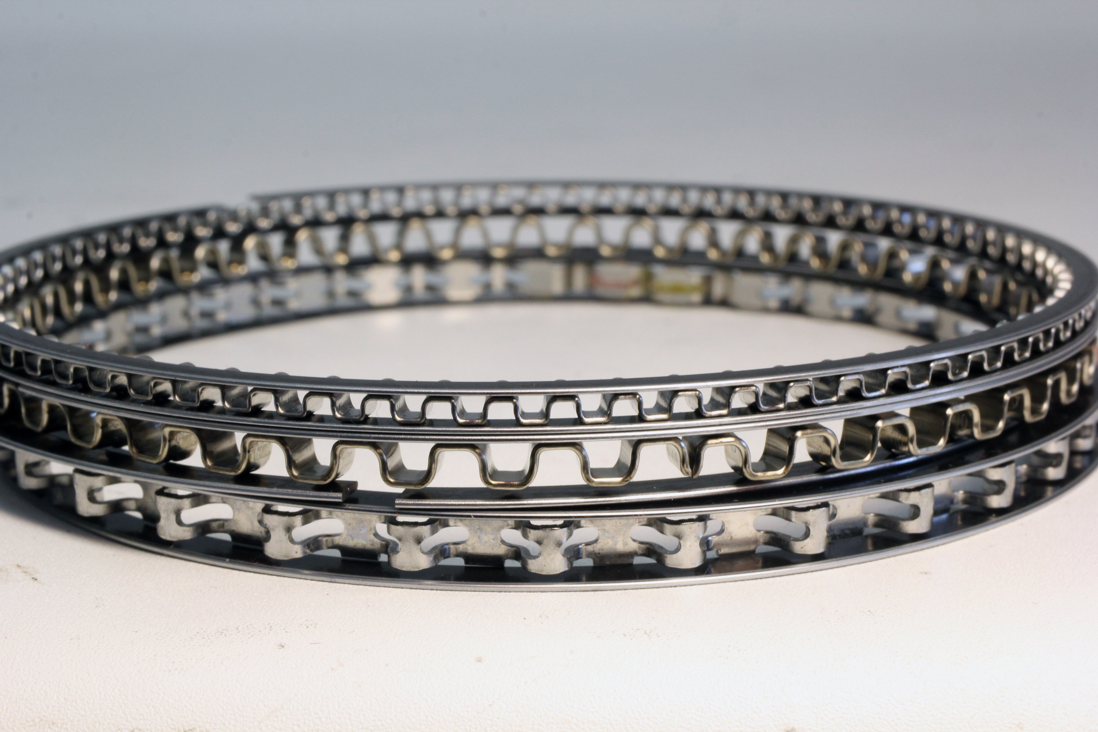
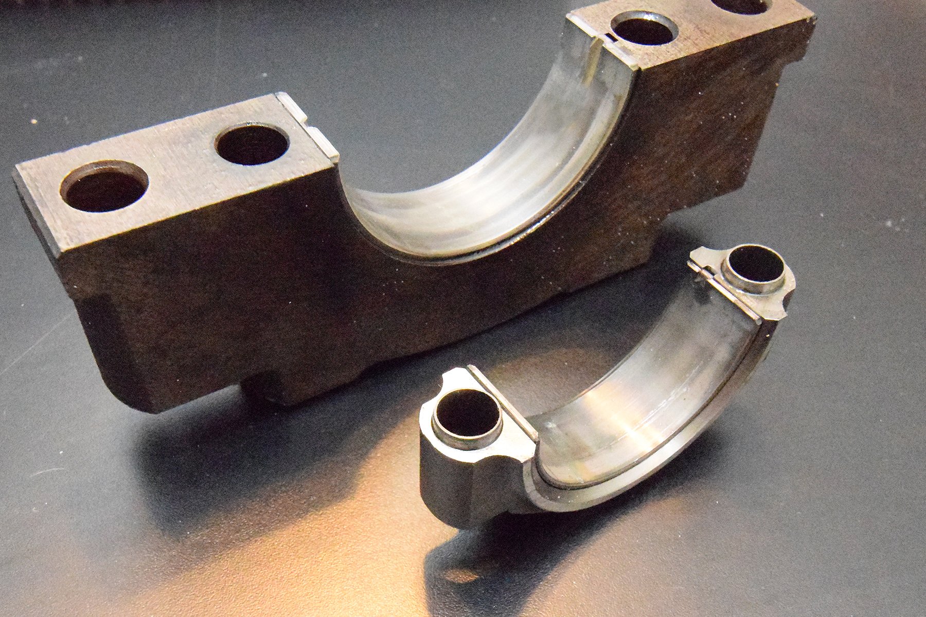
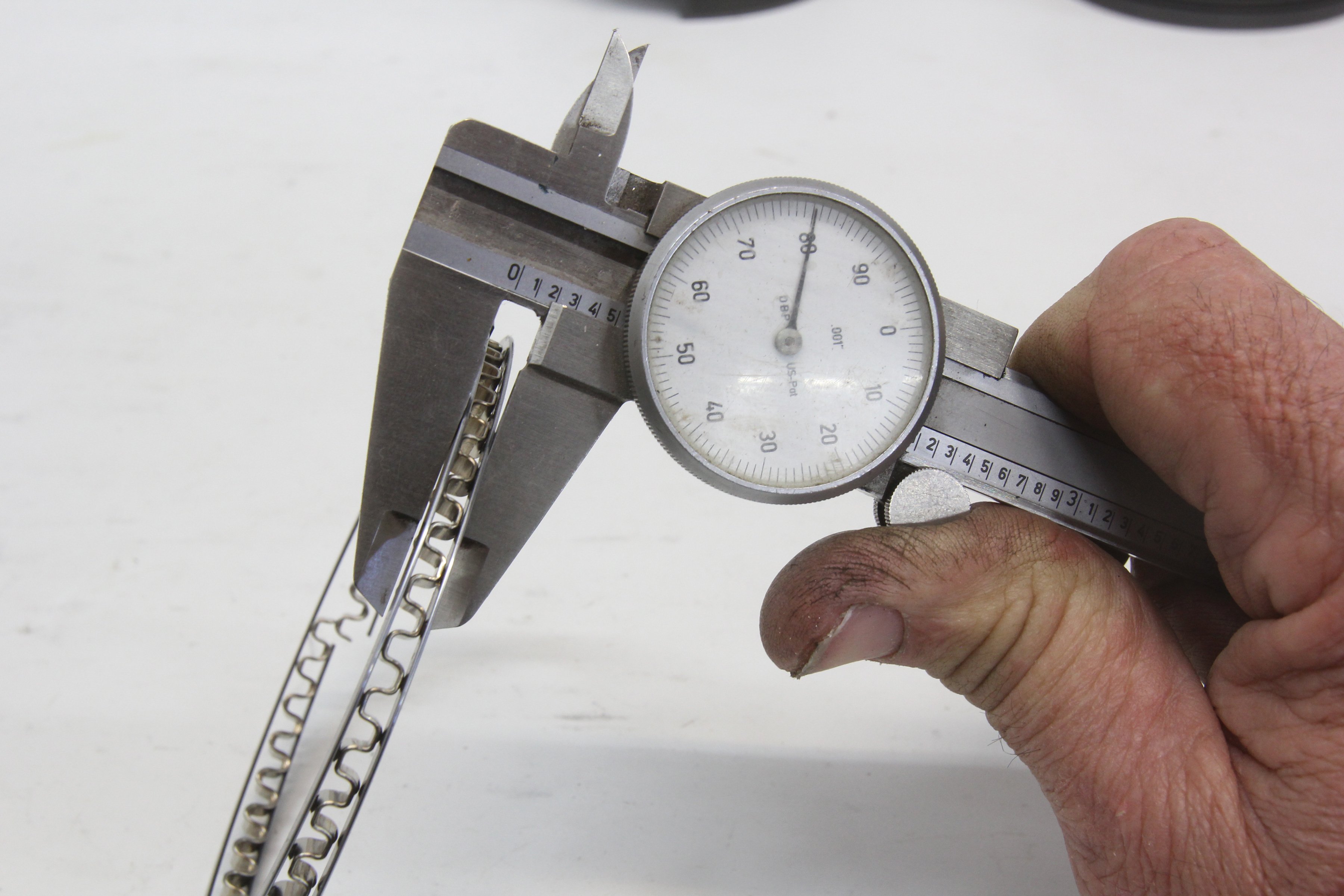
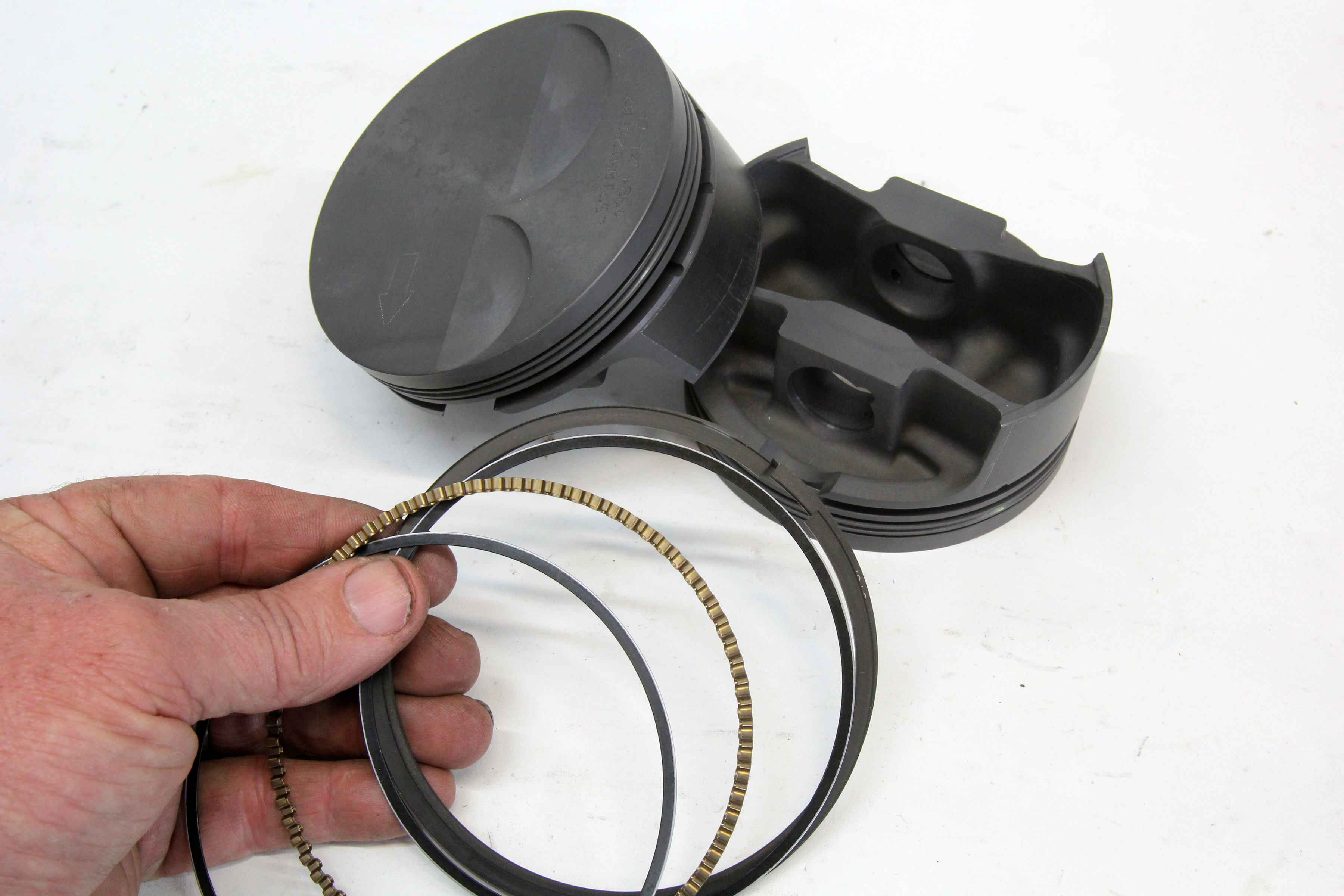
(Left) The radial width of an oil ring helps determine its radial tension. Here, we’re measuring a 3.0mm oil ring which comes in a 0.110. (Right) This stack o’ oil rings compares a stock replacement 3/16-inch (bottom), to a 3/16-inch oil ring from a 1/16-inch performance ring package with a different expander (middle), to a 3.0mm oil ring (top) as used in a typical LS 6.0L engine. The top two expanders are the more common flex vent design while the bottom is called an SSU, which is an older configuration similar to the flex vent but turned on its side. Speed says the flex vent is a more efficient design.
A typical performance piston ring combination is a 1/16-inch top, 1/16-inch second, and a 3/16-inch oil ring. A “standard” 3/16-inch (0.187-inch) oil ring package, as listed in the chart, creates a significant 20 lbf radial tension. What’s interesting is the spec for a “standard” late model 3mm (0.117-inch) oil ring package, Total Seal’s radial tension measurement plummets from 20 lbf to 11 lbf – an amazing 45-percent reduction in radial tension.
What’s worth emphasizing is that both of these oil rings are considered “standard” tension. As one example, the lowest radial tension ring — the 3mm ring — is the standard factory oil ring in late-model LS engines. What we’ve learned is that there are many ways to achieve good oil control and still reduce friction when the proper oil ring components are selected.
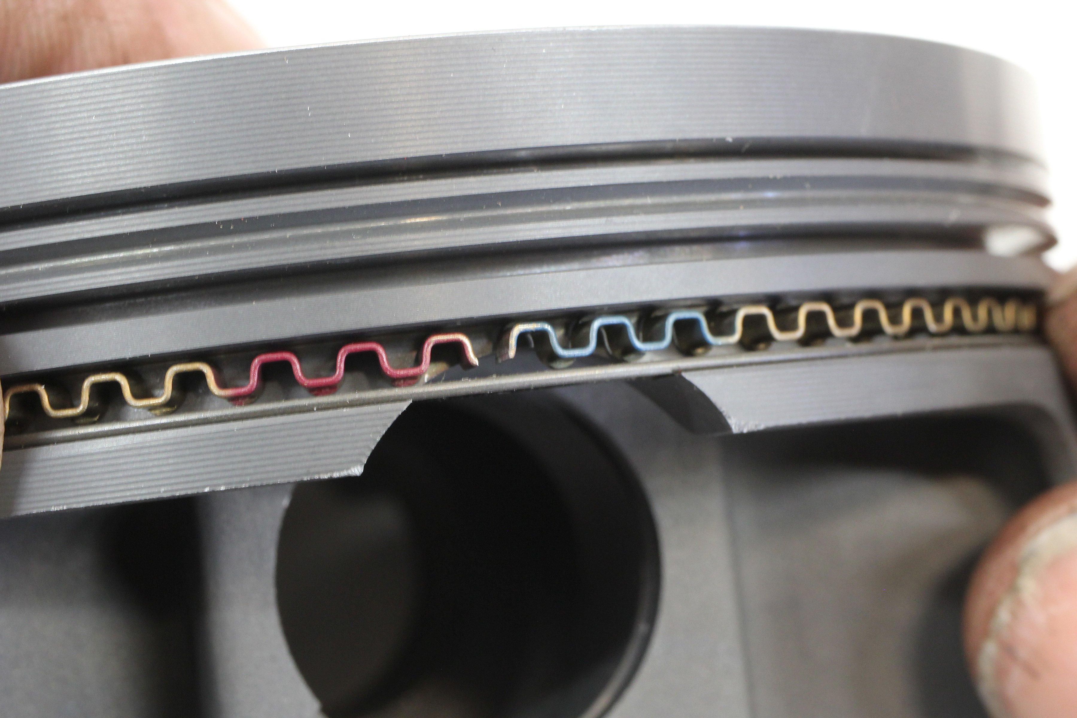
To reduce oil ring drag, most “low tension” techniques use a combination of a given expander with a thinner radial wall width oil ring. The wider oil ring in this photo is from a 3/16-inch oil ring while the narrower ring is from a 3.0mm oil ring package for a 6.0L LS engine. Both are intended for use in a 4.00-inch bore.
Less Tension, More Control
Interviews with Total Seal’s Keith Jones and Lake Speed, Jr. offer some tech-savvy insights into how these numbers directly relate to street-driven engines and how a sophisticated and knowledgeable engine builder can create his own custom oil ring package. But before we get into that, let’s look at some details about oil ring construction that will lead us to intelligently create this oil ring package.
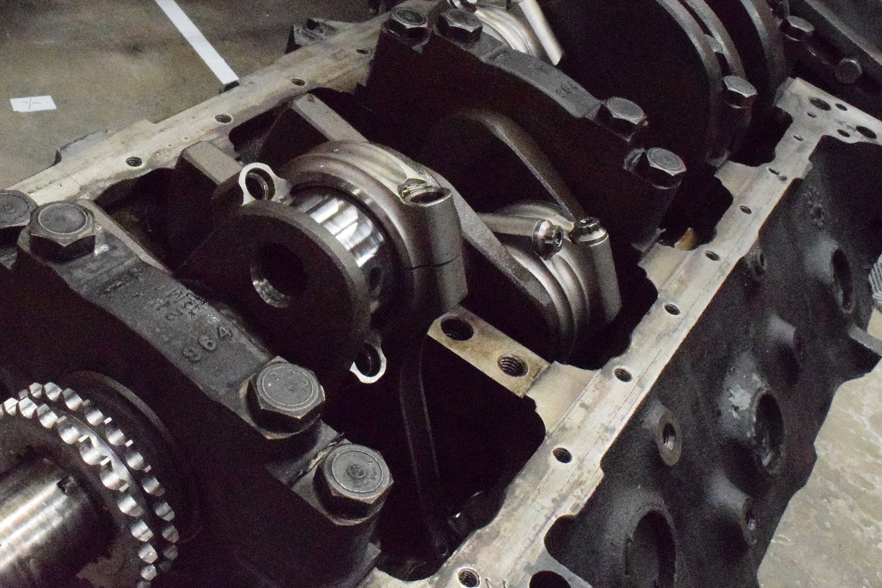
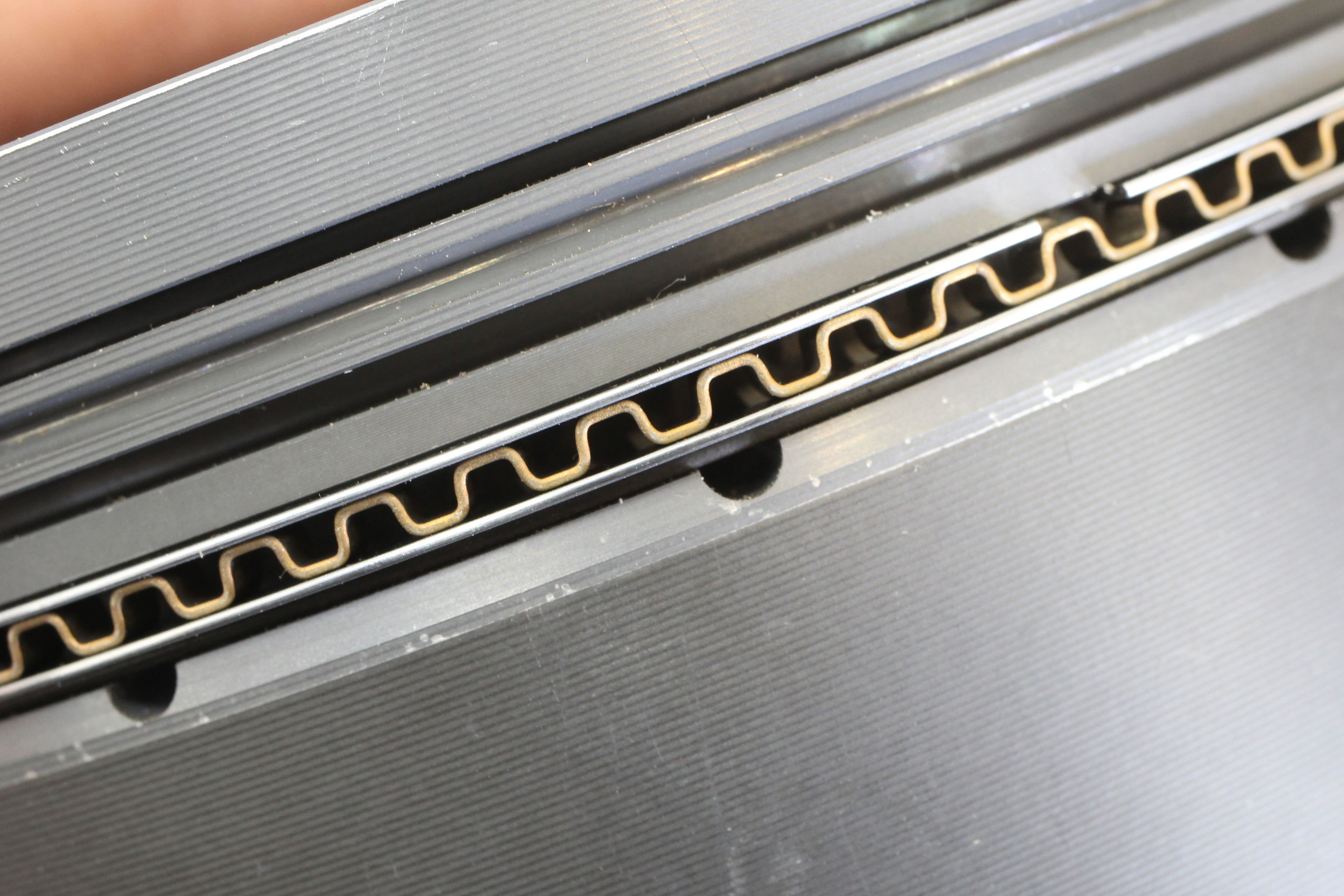
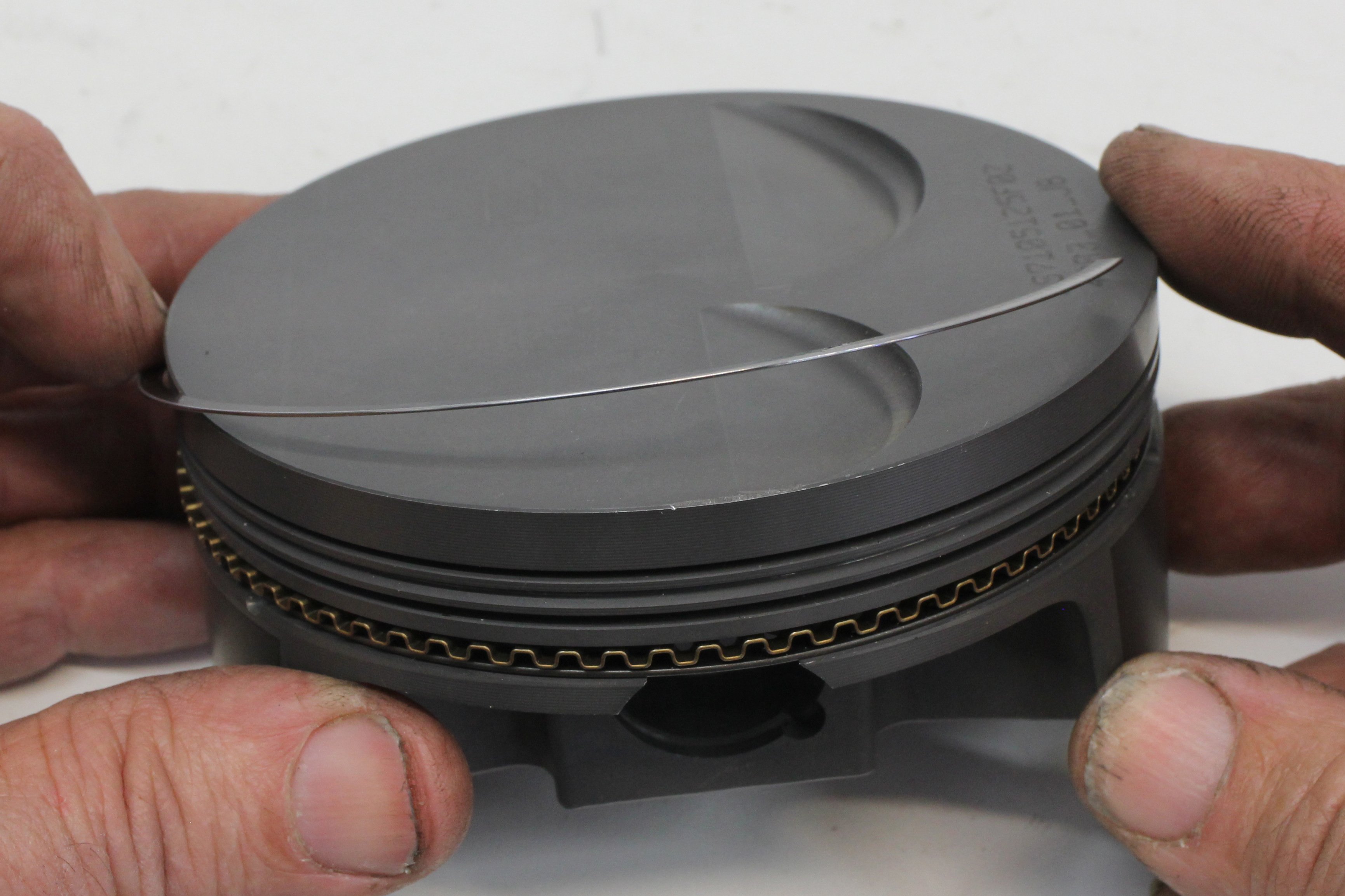
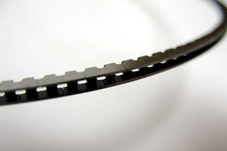
Nearly all current oil rings are created using a three-piece construction technique. The expander is the large center piece that is restrained with a pair of oil rings. The expander can be thought of as a spring that is loaded when installed in combination with the upper and lower oil rings. The oil rings’ function is to scrape oil off the cylinder wall and push it inward to oil return holes or slots cut on the inside of the piston’s oil ring groove.
Sliding Friction Test
These are some numbers we created using a simple digital fish scale on a 4.155-inch small-block Chevy bore testing a 1/16-, 1/16-, 3/16-inch ring package. Each ring was tested individually and Total Seal’s Keith Jones suggests the top and second ring numbers appear a bit high for the application while the oil ring numbers are closer to what they’ve experienced. Relative to each other, the numbers are consistent which means the oil ring offers the most potential for improvement in terms of reducing overall friction.
| Ring | Sliding
Friction |
| Top | 6 – 7 lbs |
| 2nd | 4 – 4.5 lbs |
| Oil | 18 – 19 lbs |
Think of the three-piece oil ring’s job as gross oil control. This is followed by fine control exhibited by the second oil ring. Generally speaking, 80-percent of the second ring’s job is to clean the rest of the oil not removed by the oil ring. The remaining 20-percent of its job is to help seal combustion pressure that has leaked past the top ring.
The first big revelation that Speed offered is that the oil ring’s vertical thickness has nothing to do with overall tension and ring drag. Oil control is created by a combination of the length of the expander and the radial width (as viewed from the top) of the oil rails. Speed says to think of the expander as a spring. If you place an expander inside its intended cylinder, the ends of the expander may not touch. But when the expander is squeezed between the two oil rails, the rails create the load much like adding a spacer under a valve spring to increase its tension on the valve.
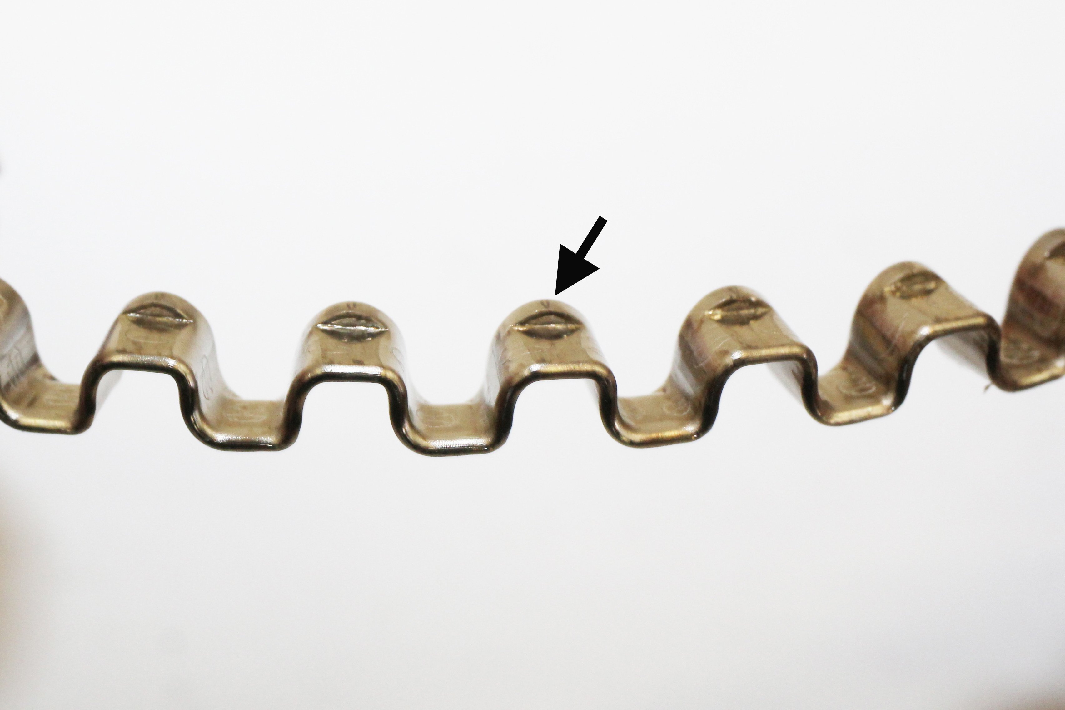
On the left, the arrow points to what Total Seal calls the tab area of the expander. The combination of tab area contact area with oil ring radial depth is what creates the oil ring’s tension. So by using different expanders and oil rings with narrower or wider radial width, Total Seal can create the near exact oil ring tension for a given application. The vertical thickness of the oil control ring is not a variable that controls overall tension. A low tension oil ring can be created with a larger 3/16-inch oil ring just as easily as with a much thinner 2.0mm oil ring (right).
The rails are also an important part of the equation. Changing the radial width of the oil ring will alter the load created by the expander. A thinner radial width oil ring will reduce the load created by the expander. We’ve created a chart where we measured the radial width of three different oil rings. Notice the major change in oil ring radial width between the 3/16-inch oil ring rails and the 3mm rails. There’s nearly a 50-percent change. Compare these numbers to the radial tension chart and there is a direct correlation between the radial width of the oil rails and reduced tension.
Oil Ring Dimensions
We measured two small-block Chevy and one LS ring package from rings we had at our shop. Note there are two different radial widths listed. The first was for a 5/64-inch ring package and the second was for a 1/16-inch ring package. The major size revision occurs between the 1/16 and 3.0mm ring sets.
| Oil ring | Oil Ring Axial
Thickness |
Oil Ring
Radial Width |
| 3/16 | 0.023 | 0.150 |
| 3/16 | 0.027 | 0.144 |
| 3.0mm | 0.019 | 0.103 |
| 2.0mm | 0.018 | 0.085 |
Beyond Standard: Even Less Ring Tension
Using this information, Speed offered that Total Seal can create nearly any desired tension for any oil ring package. Working with the example that a 3mm oil ring offers a radial tension of 10 pounds of force, a similar radial tension could be created using a larger 3/16-inch ring by combining a custom expander and oil rings. Speed said that perhaps half of Total Seal’s business is building custom ring packages that are not necessarily listed in the Total Seal catalog.
Speed offered that just within the 4.030-inch bore diameter for a 3/16-inch oil ring that Total Seal offers several different radial widths for the oil rings that can be combined with a given length of expander to create the intended overall oil ring tension spec. As an example, Speed says Total Seal could create a 10 lbf (or just as easily a 16 lbf) oil ring package for a 3/16-inch oil ring piston that would reduce friction and still control oil on a street engine.
The oil ring expander acts like a spring. When installed in the oil ring groove, the rails press down on the expander and this action exerts pressure against the cylinder wall to produce a given tension which is used to scrape oil off the cylinder wall. The important part is to ensure that the ends of the expander do not overlap when installing the rings.
But there’s more to the story. In order to be successful, a “low tension” oil ring should be combined with a Napier-style second ring. The Napier ring is a tapered scraper style ring that includes a hook or recessed area behind the tapered lower face of the ring that enhances the ring’s ability to remove oil from the cylinder wall. Speed emphasized that the combination of the Napier second ring with the custom 3/16-inch oil ring would improve oil control while also offering the opportunity to reduce friction which would result in more horsepower over a “standard” tension oil ring of the same size.
Speed further mentioned that the engine’s intended usage is an important factor in creating an oil ring package. A drag race engine that does not create high oil temperature could benefit from a different oil ring package compared to an engine that is raced in autocross where oil temperature could escalate beyond 250 degrees-Fahrenheit. So oil ring combinations should include the oil viscosity as part of the oil ring equation.
Shavers’ 383ci small-block Chevy mule engine uses a very thin but gas ported 0.7mm / 0.7mm Napier / low tension 2mm ring package that is very small yet durable. It offers excellent oil control and minimal blow-by. Speed also mentioned that during oil testing that the lower tension ring package reduced friction that not only increased power but also lowered oil temperature.
A purely drag race engine could get by with a much thinner oil viscosity such as a 0w20 while the autocross or road race engine might need a slightly higher viscosity oil like 10w30 or 10w40. If the engine in question will use a high viscosity 20w50 oil, then a higher tension oil ring will be required to more efficiently scrape the thicker oil off the cylinder wall.
A typical retort to all this is that the reduced load exerted by the oil ring will only result in poor oil control and increased oil usage. But, that does not account for the fact that GM research has chosen to employ a 3.0mm oil ring package in a 6.2L LS engine that does not have an oil control problem. One reason for this performance is that this smaller ring package and lower tension allows the oil ring to more accurately follow the distortions in the bore which means more oil is removed from the cylinder wall by both the oil and second rings.
Thin ring packages aren’t some exotic option on pistons anymore. Mahle offers many of its pistons with much thinner ring packages such as a 1mm / 1mm / 2 mm package for small-block Chevy engines as an example. This is a 4.125-inch bore Mahle LS piston.
Talk Is Cheap, Proof Is Priceless
A further example of how a custom oil ring package can perform is the 383ci small-block Chevy used as Shaver Specialties Racing Engines’ mule engine that has survived thousands of dyno pulls. It is currently equipped with a set of Total Seal 0.7mm top, 0.7mm Napier second, and an 8 lbf, 2mm oil ring package. We personally witnessed one of these pistons slide down the bore by itself (merely from the force of gravity) because of the reduced radial tension exerted by the ring package.
While this sounds like the engine should be challenged when it comes to oil control, Shavers’ dyno operator “Dyno Don” MacAskill reports that the engine has no oil control problems, the chambers stay very dry, and the blow-by is quite low. Further, this engine does not employ any special windage control measures. In other words, the oil pan is devoid of screens, trays, or other control devices.
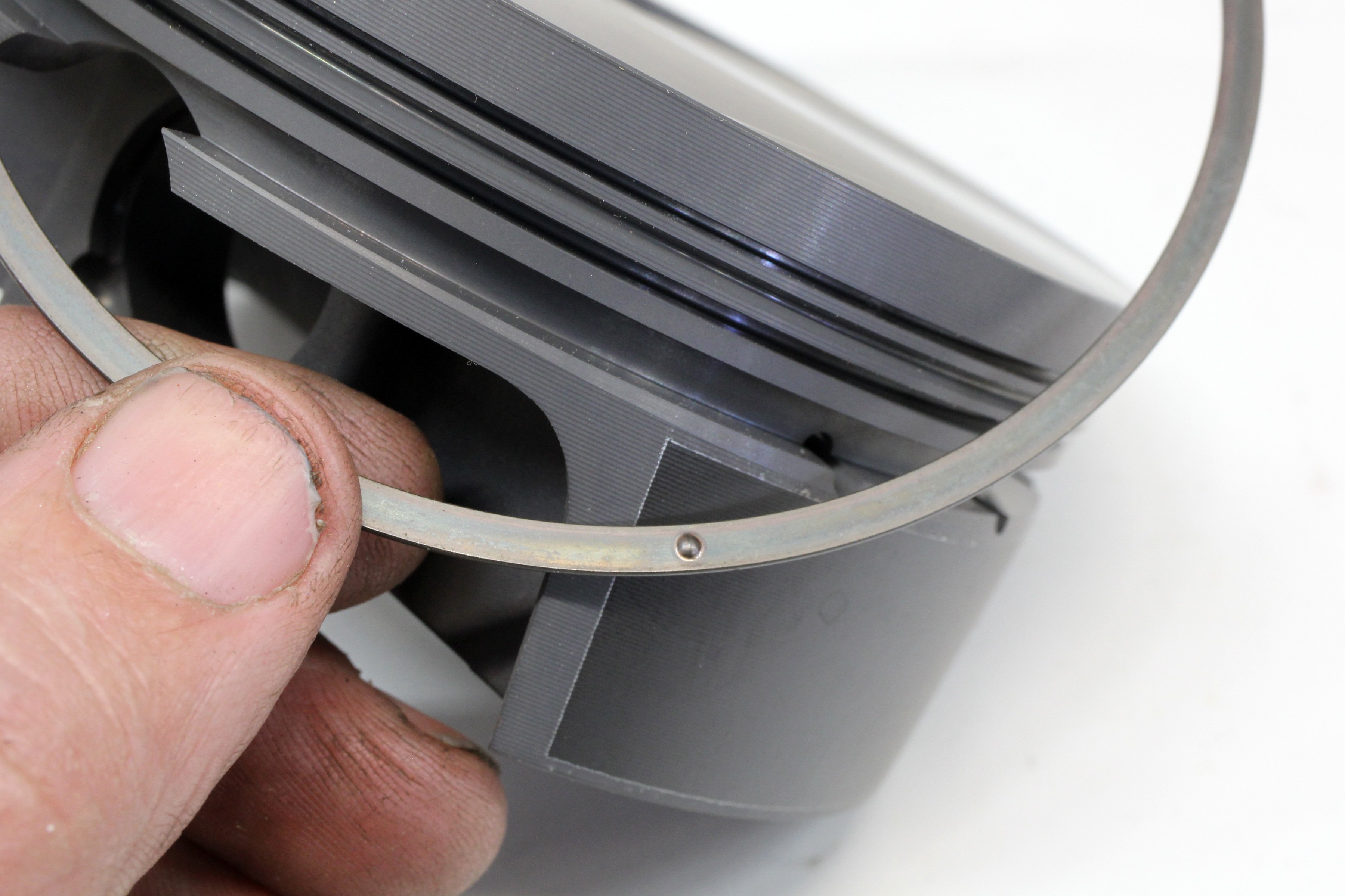
(Left) If an oil support rail is required because the oil ring groove intrudes into the wrist pin hole, always place the support rail with the small dimple facing down. The dimple contacts the piston and prevents the support rail from moving. (Right) When installing the oil ring, make sure to Install the expander first and make sure the ends of the expander do not overlap. Then gently install the top oil rail followed by the lower rail.
As for a practical street engine application for all this acquired knowledge, let’s stick with a typical 1/16-, 1/16-, 3/16-inch ring package engine. The consideration would be to use a lower tension oil ring package with a custom expander nested with thinner radial width oil rings combined with a Napier second ring. This would measurably reduce friction while still minimizing oil consumption.
For high-end competition engines like NHRA Pro Stock or NASCAR, Total Seal also has a one-piece oil ring that is also extremely flexible.
Armed with this new information, you might want to consider the advantages of building your next engine with more attention paid to the lowly oil ring. It might just pay off with a little less friction and a touch more horsepower.