Posted on Leave a comment

Why You Should Run Nitrous On A Boosted Engine

Boost-N-Juice


For years nitrous, supercharger, and turbo companies have pushed enthusiasts to use one or the other. You were either going to be a fan of boost or nitrous oxide, but not both. They were like oil and water as you would hardly ever find someone using these power adders in conjunction at the track or on the street. Today, it’s not uncommon to find boosted cars with nitrous, as well. Street Car Takeover and other events even allow for multiple power adders permitting the enthusiast to get the most out of their vehicles. One company that has pushed these boundaries in the last five years is Nitrous Outlet. But, it hasn’t always been that way. We reached out to Dave Vasser, owner of Nitrous Outlet, to see what’s changed and to get the inside scoop on injecting nitrous into a supercharged or turbocharged application.

LSX Mag: Why do you support nitrous and boosted combinations?

Dave Vasser: I owned a speed shop for many years back in the early 2000s. I wasn’t much of a boosted fan at that time, however, superchargers and turbochargers have come a long way in technology and dependability. Now, performance vehicles are coming from the factory with blowers or turbos on them. There is only one way to top the increased performance and drivability of a boosted street application, and that is adding nitrous. Now you can have the drivability with all-out performance when you’re ready to get after it. 

LSX Mag: How do nitrous and boost work in unison?

Dave Vasser: The best way to explain the benefits of using nitrous on boosted applications is to address how each power-adder increases the engine’s performance.  

Nitrous and boost both provide the ability to increase the air pressure within the combustion chamber. The higher the air pressure, the higher the air molecules are. The higher the air molecules are, the higher the oxygen content is. When the oxygen content is high, more fuel can be burned. This increases combustion and cylinder pressure, enhancing the speed at which the piston is pushed back down into the cylinder. This process creates additional “horsepower.” In simple car guy terms, Oxygen + Fuel + Cylinder Pressure = Horsepower. 

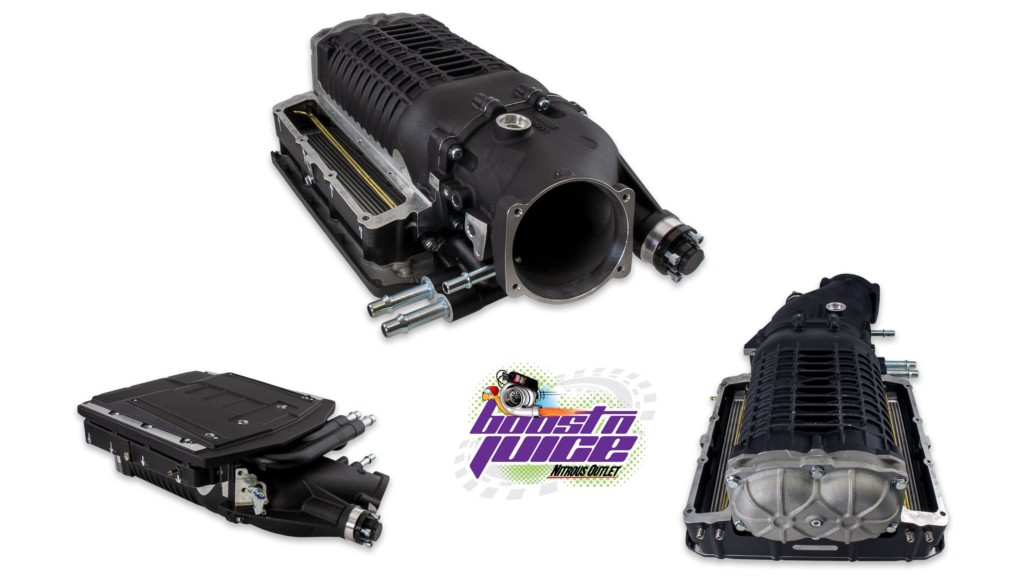
The Nitrous Outlet Interspooler is an excellent addition to both centrifugal superchargers and turbochargers alike.

Nitrous Oxide is a compressed liquid composed of two parts nitrogen and one part oxygen. Due to high combustion chamber temperatures, as the nitrous enters the combustion chamber, it breaks down, separating the nitrogen and oxygen molecules. As the bond breaks apart, the nitrogen acts as a heat absorbent, and the oxygen increases the ability to burn more fuel.

Boost is created from compressed air that is forced into the combustion chamber. The engine can receive more air due to the compressed air than it would pull in naturally, hence the term forced induction. Increasing the combustion chamber’s air pressure increases the oxygen content, which increases the ability to burn more fuel. This enhances the combustion process, which increases the cylinder pressure, returning the piston at a faster rate of speed.

LSX Mag: How does nitrous help turbo applications?

Dave Vasser: A turbo relies on exhaust gases from the engine to spin the turbine and create boost. The turbo will continue to build pressure as the power plant increases RPM, so the power increase is not instant. Engine and turbo combinations that are not perfectly matched will not be as efficient. Too small of a turbo will spin the turbo faster, creating excess heat, and too large of a turbo will have issues spooling. However, adding nitrous will instantly boost the engine’s cylinder pressure, building RPM immediately while knocking down the cylinder temperatures. 

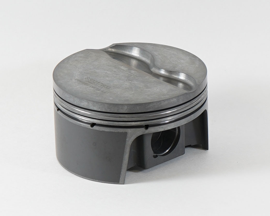
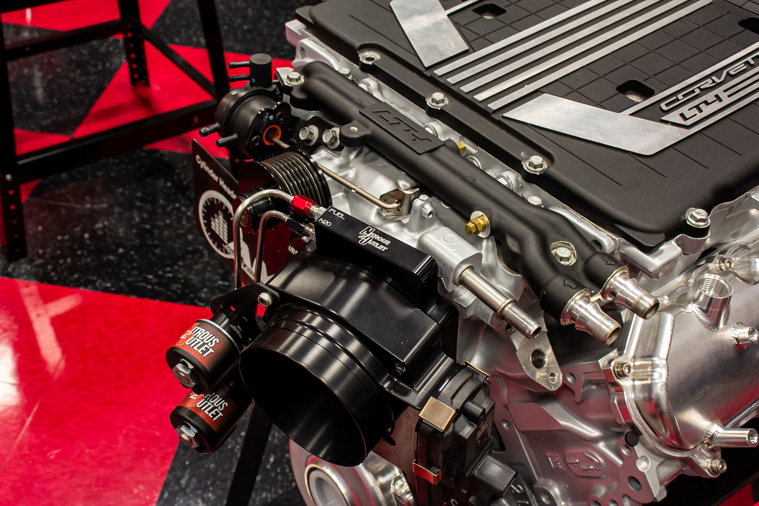
This particular engine has an Interspooler and a direct port system for the maximum with cylinder to cylinder tuning and plenty of additional horsepower on tap.

LSX Mag: How does nitrous help supercharge applications? 

Dave Vasser: Supercharger applications don’t suffer from delayed boost like turbo applications, however, they do rob some power from the engine due to how they build boost. A roots-style supercharger forces air into the engine through rotors that are driven by the engine’s crankshaft. A centrifugal-style supercharger forces air into the engine through a compressor design, similar to a turbo but the compressor is driven by the engine’s crankshaft. Both styles of superchargers will build boost as the engine gains RPM. Engine and supercharger combinations that are not perfectly matched will not be as efficient. Too small of a supercharger will spin faster, creating excess heat, and too large of a supercharger will have issues building boost. Adding nitrous will create an instant boost by providing instant cylinder pressure, making the engine build RPM instantly while knocking down the cylinder temps.

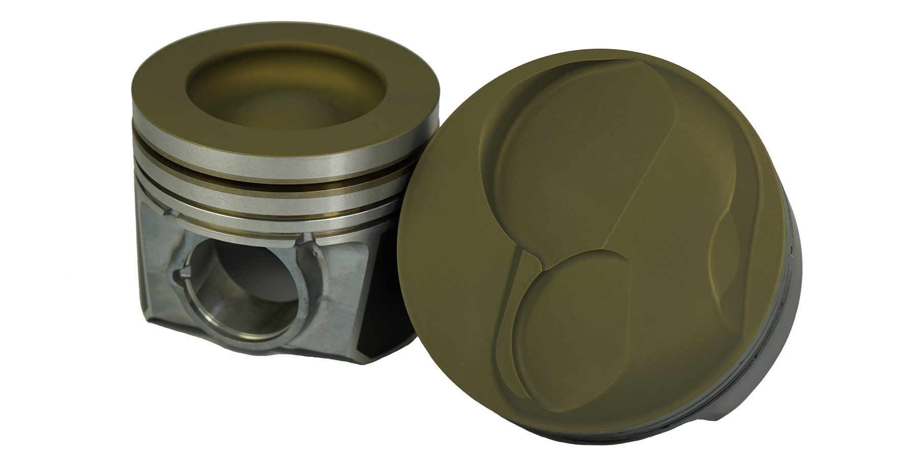
If you have a roots style supercharger, Nitrous Outlet can customize most brands by adding spray bars that discharge on the inside.

LSX Mag: Does any style of nitrous system work better than another when it comes to spraying nitrous?

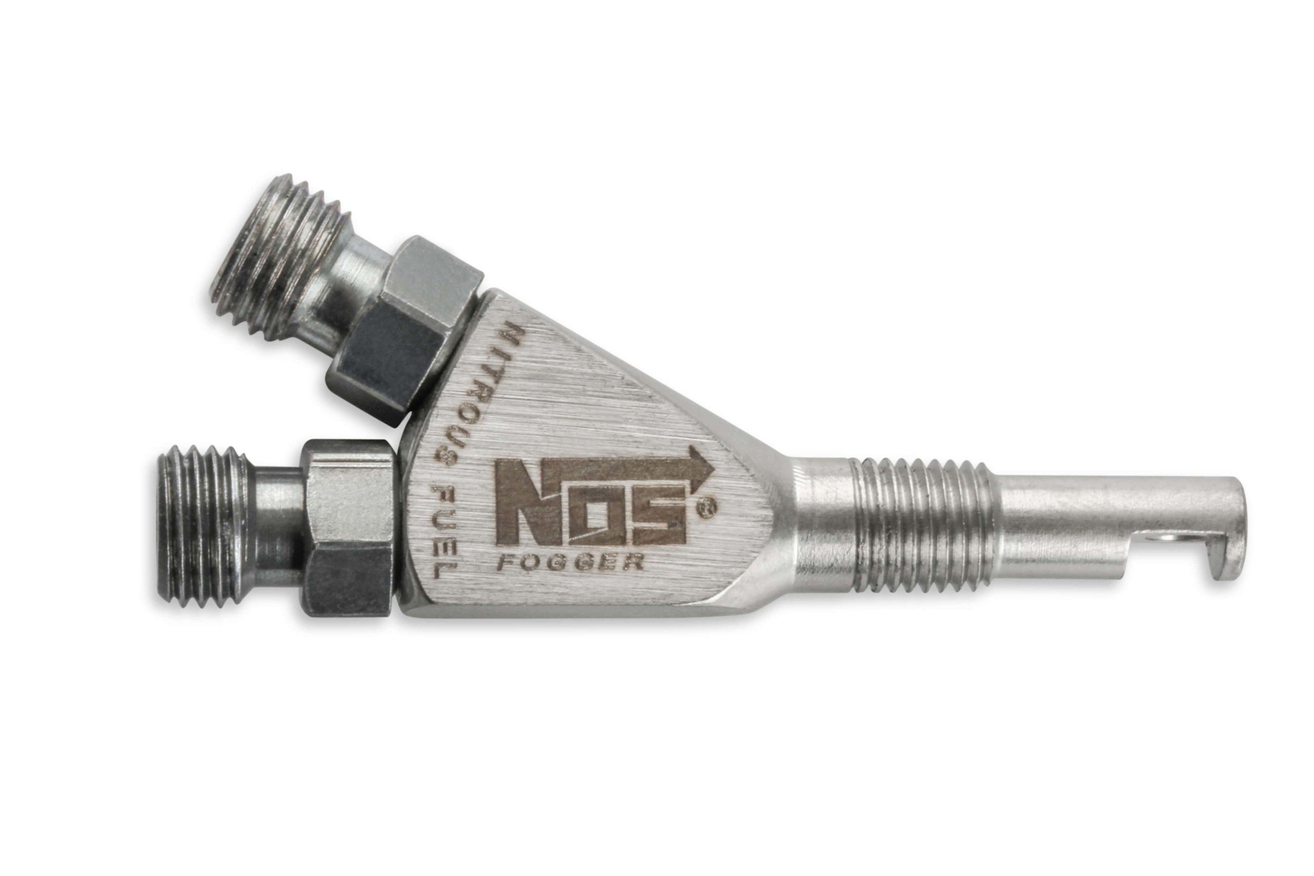
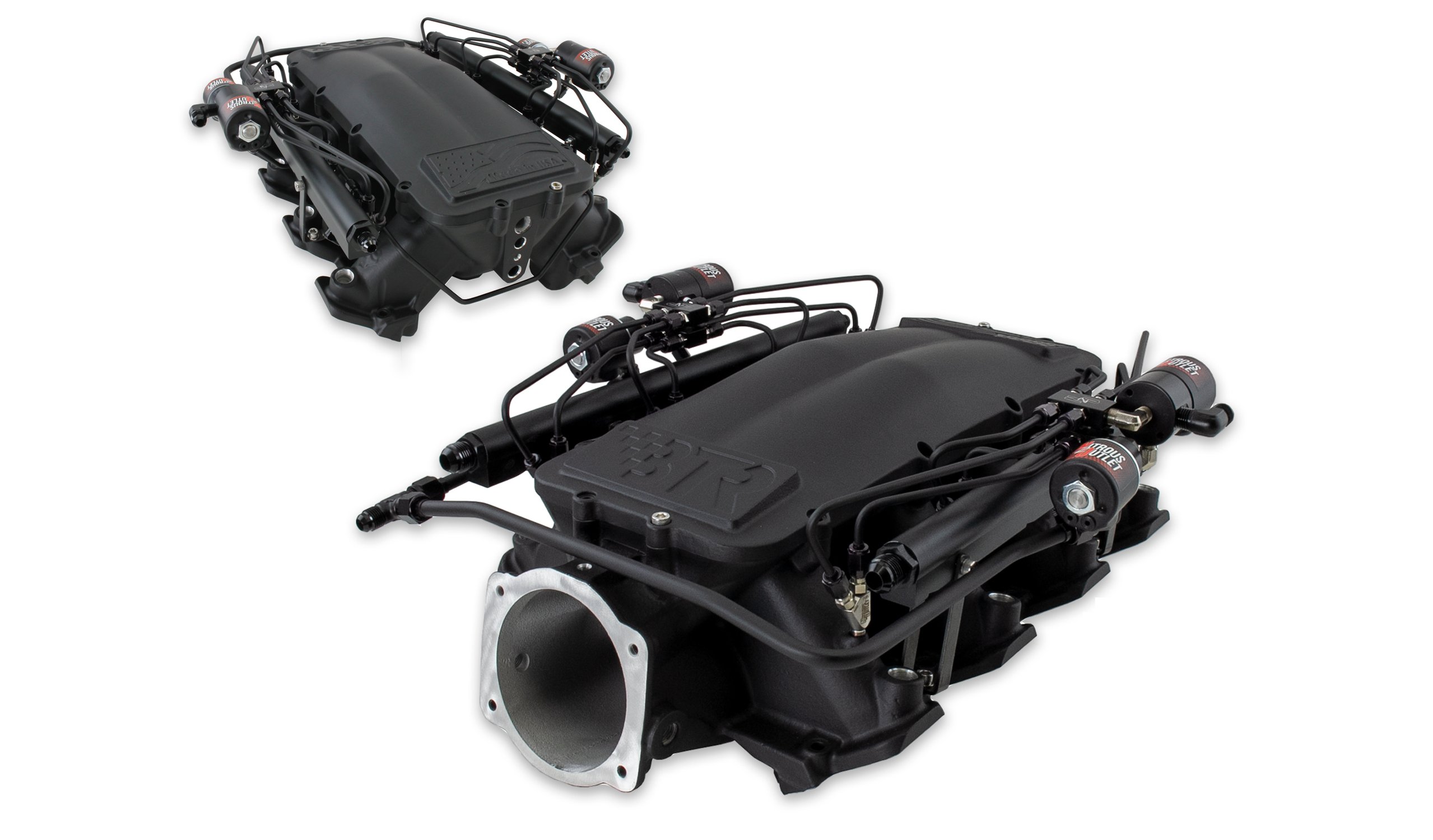
Dave Vasser: It comes down to how much nitrous is being added. If you’re injecting a lot of nitrous, a direct-port system may be your best option. A direct-port system will inject the nitrous directly into each cylinder, ensuring each cylinder is getting the same amount of nitrous. If you add a small amount of nitrous, there are many options, including a single nozzle in the air tube, an Interspooler plate system installed in the air tubing, or a throttle body plate on the intake manifold. 

The key is to saturate the air intake charge. The further back in the air intake tract, the longer the nitrous has to knock down the air temperatures. The more saturation the nitrous discharge has into the airstream, the better the distribution will be with the ability to knock down air temps. You can move the discharge point further back in the airstream on dry applications that add the nitrous system’s fuel through the injectors. On a wet system, which adds fuel with the nitrous, the discharge needs to be no further than six to eight-inches from the throttle body or intake manifold entrance. 

LSX Mag: What should you look for when running nitrous on a boosted application?

Dave Vasser: As with any performance modification, knowing the limitations of the engine components, fuel system, and ignition system are just as important as having a proper tune-up. It’s also important to keep intake air temps low to help suppress detonation. 

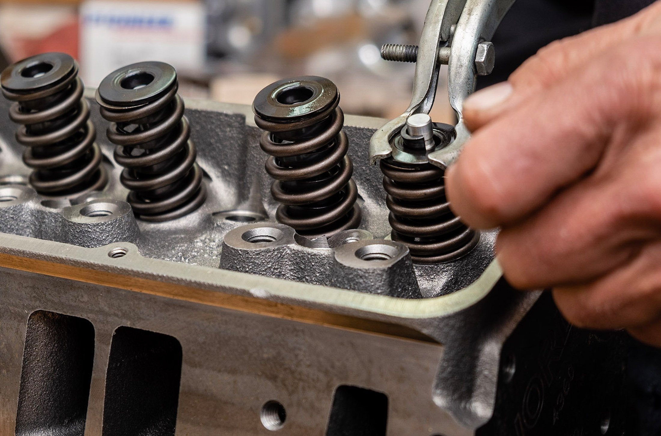
Nitrous plates mounted behind the throttle body are also a popular option among boosted performance enthusiasts.

LSX Mag: What does nitrous do for a boosted engine in high altitude or “bad air?”

Dave Vasser: To properly answer this question, you need to understand air density. Air pressure is dependent on air density. The more dense the air, the higher the air pressure will be, meaning more air molecules. The less-dense the air, the lower the air pressure will be, indicating fewer air molecules. 

There are three main factors that affect air pressure, which will impact an engine’s performance. 

  • An increase in elevation or altitude decreases atmospheric pressure – Atmospheric pressure is the force exerted on a surface by the number of air molecules above it as gravity pulls it to the earth’s surface. As you increase elevation or altitude from the earth’s surface, it decreases the air pressure, which means fewer air molecules.  
  • Increased intake air temps and decrease the air density – The colder the air is, the denser it becomes. The warmer the air is, the less dense it is. This means there are fewer air molecules. 
  • Water content or humidity – Moist air is less dense than dry air, which means the higher the water content, the less compact the air is. As a result, there will be fewer air molecules. 

All of the above examples will all equate to less air molecules = less oxygen = less fuel burned = less power. 

In simple terms, boosted applications compress the outside air by forcing it into the engine. If the air quality is poor, the oxygen content is too. Adding nitrous provides the oxygen content needed to burn more fuel and make instant power. 

If you’re running a Whipple and want additional power and a cooler air charge, custom nitrous spray bars are the way to go.

LSX Mag: How does nitrous cool the intake air temps on boosted applications?

Dave Vasser: Forcing compressed air into an engine will build heat, which reduces the oxygen density. As nitrous leaves the discharge port and enters the airstream, it will expand, turning from a liquid to a gas with a temperature of around 129-degrees Fahrenheit below zero. This cooler temperature means the air is denser and will significantly reduce the air intake temperatures. Adding nitrous will increase horsepower, and due to its cold nature, it will act as a cooling agent. This knocks down the intake air temps and helps aid in detonation.

LSX Mag: Will you need to change your tune-up for boost and juice?

Dave Vasser: As you increase power on any application, whether it be naturally-aspirated, boosted, nitrous-assisted, or boost and juice, you will need to alter the tune. The engine will need higher octane fuel, more fuel, less timing, and a colder spark plug. 

LSX Mag: How should you address a timing map when spraying nitrous on a turbocharger or supercharger application?

Dave Vasser: You will set up the timing ramp to remove timing as the nitrous activates. The amount of timing will be dependent on how much nitrous you’re adding. The odds are that the system will increase in boost due to the improved air quality, so even if you’re adding a small amount of nitrous, adjusting the timing to compensate for the change is crucial.

LSX Mag: Do you see better results when spraying a supercharger or turbo?

Dave Vasser: Both a turbocharger and supercharger can greatly benefit from adding nitrous. The results vary with different applications. Keep in mind that keeping intake air temps down helps aid in detonation. Applications that are non-intercooled will have increased air temperatures, as well as applications that are over-spinning the blower or turbo.

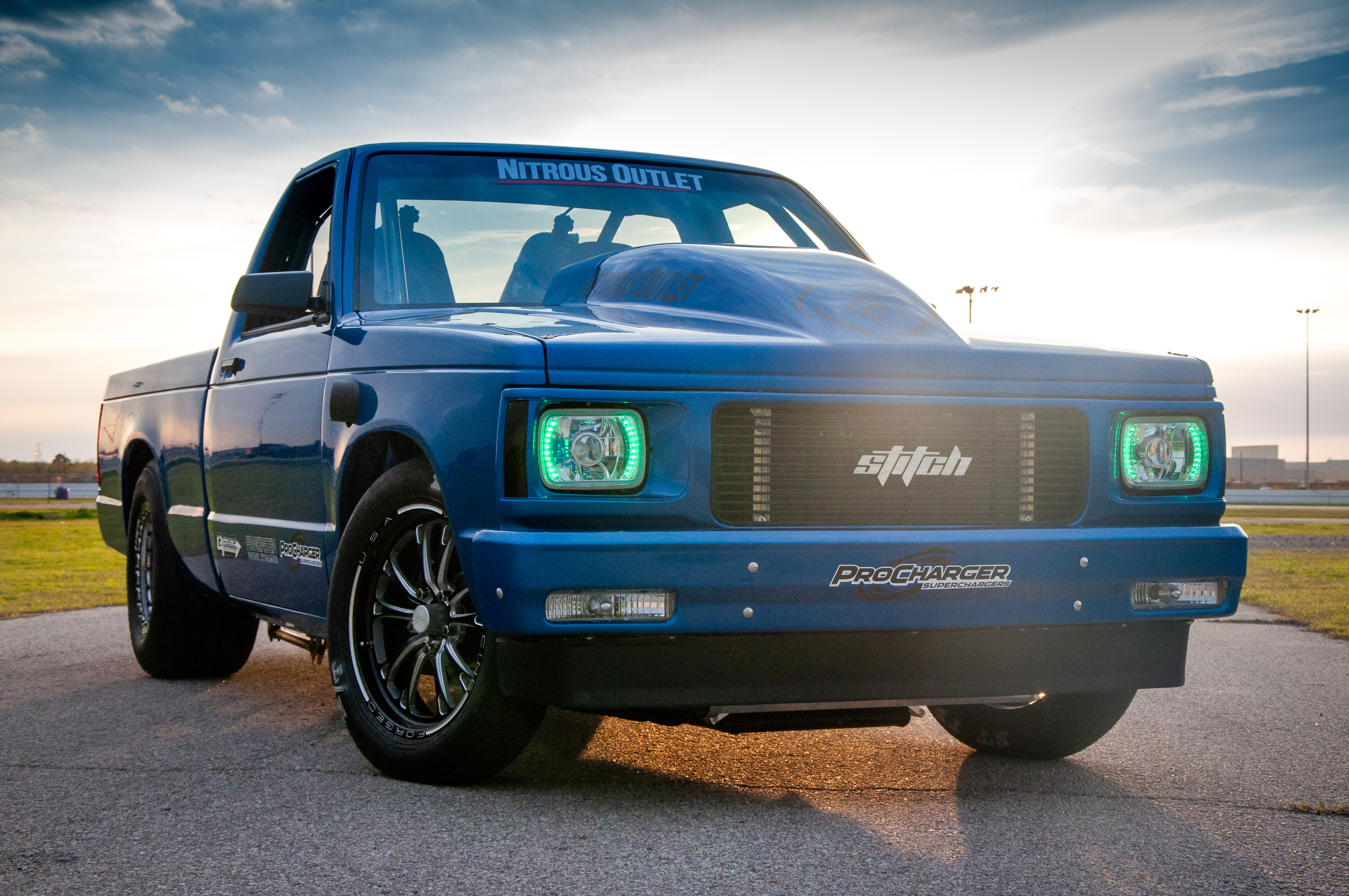
Nitrous Outlet has realized the potential of boosted applications with nitrous, and they even built an S10 to test new products with. 

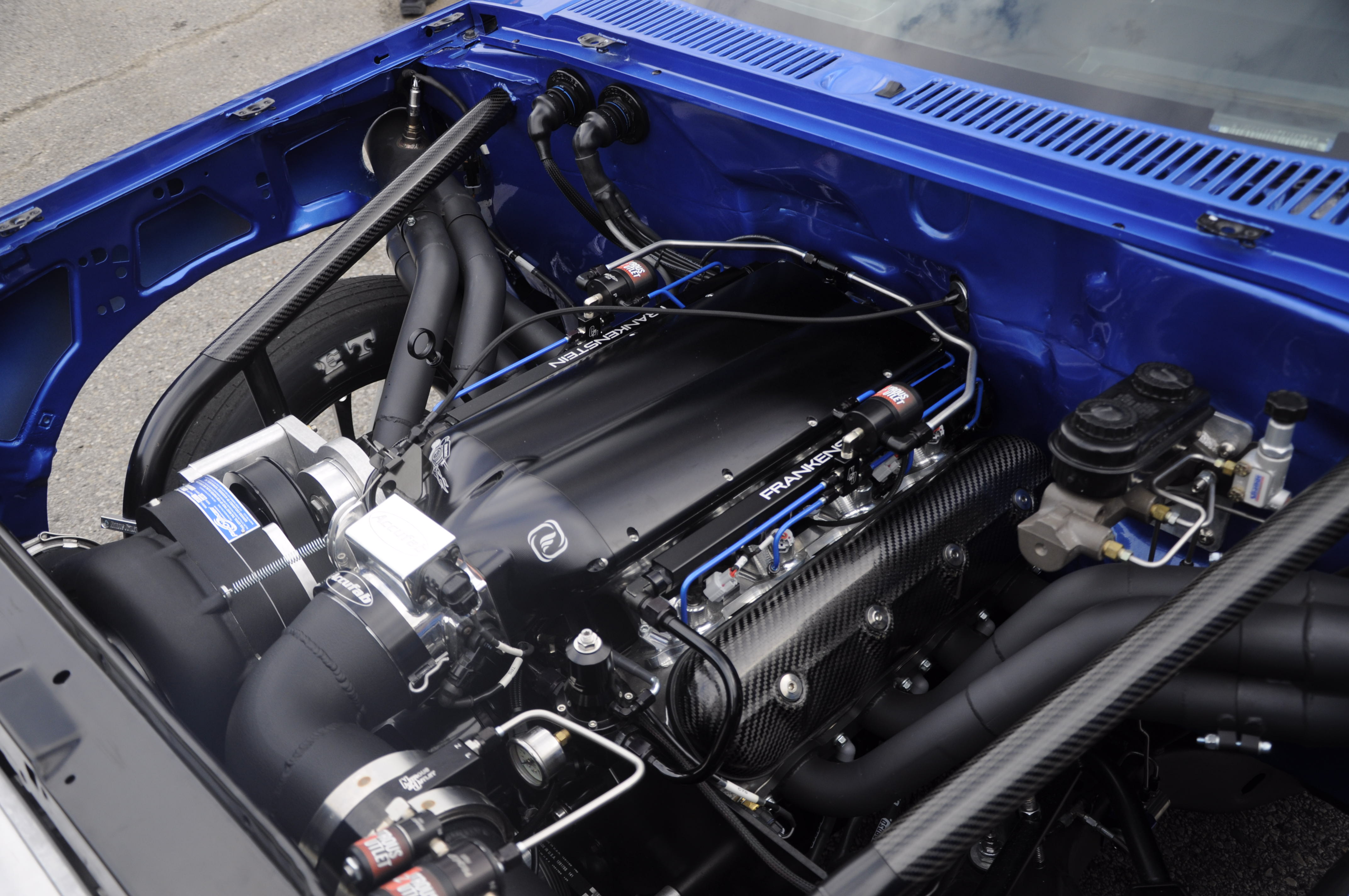
This S10 truck known as Stitch houses a ProCharger centrifugal supercharger along with a Nitrous Outlet Interspooler plate and a direct port system.

“We built a 1993 S10 called “Stitch” to market Nitrous Outlet’s Boost-N-Juice program. This truck is a real head-turner, and it’s a blast to drive. It currently makes around 850 horsepower on a stock LS bottom end with a set of Frankenstein LS3 heads, an F1A-94 ProCharger, and a 100 horsepower shot through the Interspooler plate,” Vasser shares. “Thompson Motorsports is currently building a 427 to replace the stock short block. Once we swap out the engine, we expect to make around 1,500 horsepower and utilize the direct-port nitrous system and a Frankenstein billet intake.”

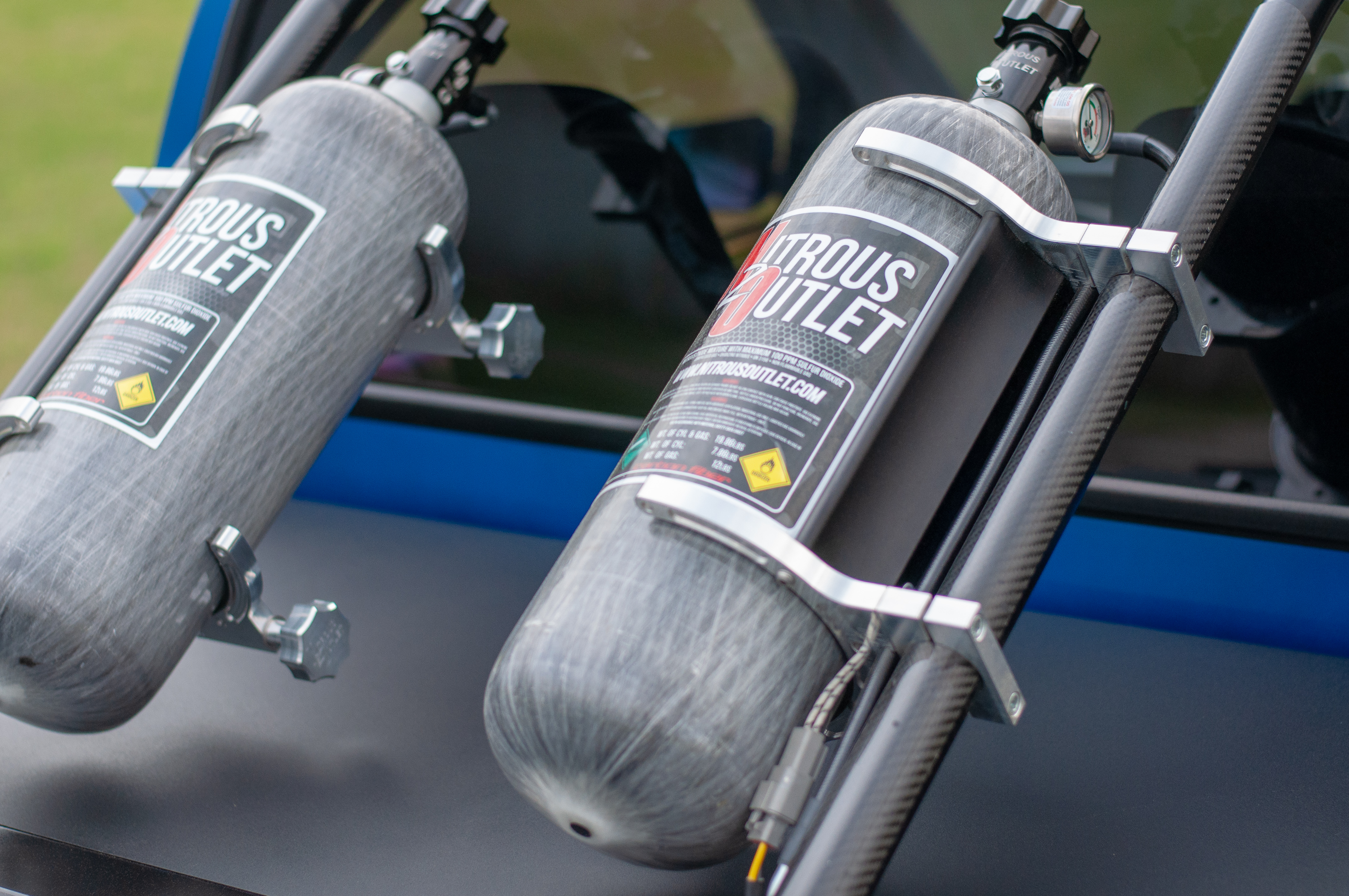
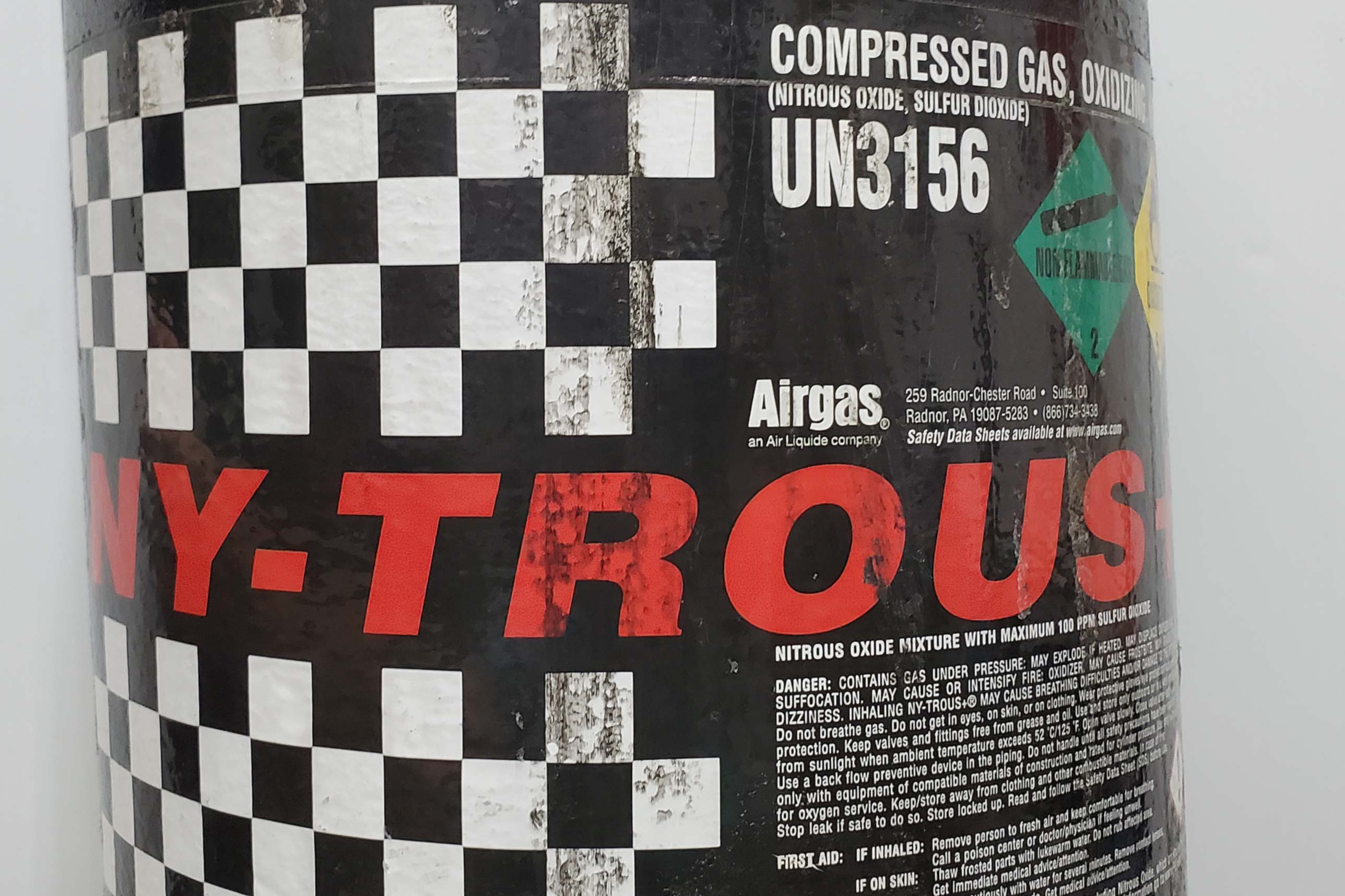
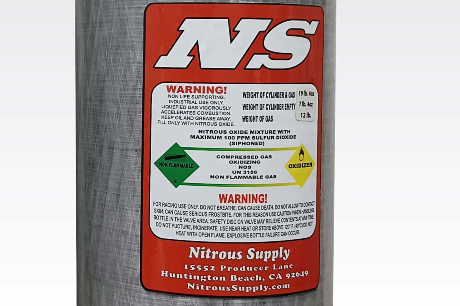
Nitrous Outlet offers a ton of nitrous systems and accessories to set your vehicle apart from the others. These 12lb composite bottles and billet bottle brackets are just tips of the iceberg.

It’s exciting to see the market change as companies like Nitrous Outlet and others encourage the use of its products with other power adders. Obviously, there’s a lot of added benefits to running nitrous on a boosted application, so it makes sense. This potent combination will give a boosted car the best of both worlds, and who wouldn’t want that? Nitrous Outlet offers a ton of innovative nitrous systems that will work with many different boosted combinations. If you have a question, give them a call or visit their website for more information. 


Article Sources

Posted on Leave a comment

Nitrous Oxide 101

Why is it that when people hear the term “Nitrous”, they automatically assume that there is going to be an explosion? Nitrous along with turbos and superchargers have been around for decades and are all a part of the “forced induction” family. You don’t ever hear things about turbos or superchargers in relation to massive explosions, but mention the word nitrous and people automatically picture their engine as the Nevada Atomic Test Range. Just for the record, there have many engine catastrophes with using all forms of forced induction.

Nitrous has always gotten a bad rap, but that’s partially due to the fact that it is the least understood power adder among the average gearhead. Nitrous is like anything else, it needs to be properly tuned. In order for it to be properly tuned, you have to get a basic understanding of what you are dealing with. If you purchase a nitrous kit today and follow the manufacturer’s installation instructions and tuning tips, there really shouldn’t be any problems.

That said, let’s go over some of the basics of a nitrous system and some tuning tips and maybe we can eliminate some of those frightening tales of “Nitrous engines gone bad”. This article will just scratch the surface, as you can dive deep into the world of nitrous oxide theory and hardware. This is just meant to help you get a basic understanding of a very misunderstood topic.

Nitrous Oxide (N2O) has both medical and industrial uses. The industrial-grade gas has 100ppm Sulphur Dioxide added to it to make it extremely unpleasant to inhale. While medical-grade Nitrous Oxide is pure, the minute amount of SO2 in industrial Nitrous doesn’t affect performance.

The Basics of N2O

First of all, let’s cover what Nitrous really is. Nitrous technically is called Nitrous Oxide. This is because the scientific abbreviation is N2O in which we are all familiar with. This means that there are two nitrogen atoms with one oxygen atom. People often associate this with the term “Laughing Gas” because it has been used as an anesthetic in the medical field.

There are generally two grades of Nitrous Oxide: medical grade and commercial grade. The medical-grade does have a higher purity rate for its intended purpose in the medical profession. The commercial-grade is what is used in our engines. The biggest difference between the two is that the commercial-grade is “tainted” with 100 parts-per-million of Sulfur Dioxide, which gives it somewhat of a foul odor. This was done intentionally to prevent improper use of the gas via inhalation.

Nitrous Oxide does not occur naturally, it has to be manufactured. It is stored in a pressurized tank in liquid form at room temperature. When it is released into the atmosphere at ambient temperature it becomes a gas in a very endothermic phase change (it gets to -127 °F as it turns into a gas). Regardless of what you might hear or see in the movies, Nitrous Oxide is not flammable and it will not burn.

While Nitrous tanks are usually made out of aluminum, most companies offer modern lightweight tank options, like these carbon-fiber bottles from Nitrous Supply. They have to meet the same 1,800 psi minimum rating and have all the same safety features as the traditional bottles, at a lighter weight.

That being said, Nitrous tanks have to be regularly certified to be able to withstand 1,800 psi. An additional safety feature, most Nitrous bottles are outfitted with what is known as a safety release disc which is made of copper or brass. If the bottle’s pressure were to rise above the 1,800 psi mark, the safety disc is supposed to blow out and release the pressure in a more controlled manner to keep the tank from rupturing. Generally, Nitrous bottles are targeted for 850-1,000 psi working range, so the 1,800 psi rating allows for a significant safety margin.

While the safety disc is a simple and effective means of protection, it does release all of the contents of the bottle once it is “released” and can be hazardous in and of itself, which is why any sanctioning body will require the safety valve to vent to the outside of the vehicle. There are also various manufacturers of different styles of safety valves that will only vent small amounts of Nitrous without dumping the whole tank. Nitrous tank pressure for a Nitrous Oxide system is very important for proper operation.

The Chemistry of Horsepower

To be able to safely use Nitrous, we need to understand what happens when it’s injected into an engine. There are two methods of injecting Nitrous, known as wet and dry. In a wet setup, additional fuel is injected into the engine along with the Nitrous. In a dry system, it’s just the nitrous that’s injected into the system, relying on the engine’s existing fuel delivery system to enrich the mixture. Either way, nitrous requires additional fuel to make more horsepower.

So, if Nitrous isn’t flammable, how does it make that power? Nitrous is a chemical compound known as an Oxidizer that releases oxygen when reacting with another substance. With its chemical makeup, each molecule of Nitrous Oxide brings with it an oxygen atom. Additional oxygen allows more fuel to be burned. More fuel burned means more horsepower. Additionally, remember how we mentioned the cooling effect when it transitions from a liquid into a gas? That radically decreases the intake charge temperature making for a more dense intake charge. The increased charge density with the additional oxygen and fuel is what makes power.

As you can see here, Nitrous isn’t flammable. Instead, it’s an oxidizer, which means it will provide additional oxygen to another chemical reaction. By adding oxygen to the combustion process, Nitrous Oxide allows more fuel to be burned in the combustion process, and more power to be made.

The ratio of Nitrous to additional fuel is the key to making safe horsepower. You’ll often hear people referring to jet sizes in a two or three-digit number. That is the orifice size, in thousandths of an inch, of the flow-restrictor in the line. In a wet kit, there will be a similar jet on the supplemental fuel line. By altering the size of the nitrous jet, more or less horsepower can be added. You then fine-tune the air-fuel ratio with the fuel jet size.

Applying Nitrous Oxide Safely

Where things go bad when using Nitrous, is often with the ignition timing. To really understand how to make power with Nitrous, we need to understand proper ignition timing with the increased rate of fuel burn along with expansion and cylinder pressure. No matter what, the ignition timing has to be changed when using nitrous to prevent engine damage.

So far, we have discussed that additional oxygen along with additional fuel increases the burn rate during combustion. The accelerated burn rate itself does not increase horsepower. The accelerated burn rate however does create a rise in heat, which in turn creates more cylinder pressure. That additional cylinder pressure is what creates power. Controlling the peak cylinder pressure of the combustion event is the key to making maximum power. Peak combustion pressure is achieved when the air/fuel mixture is ignited right before it reaches peak cylinder pressure (from piston compression) in the chamber.

Here you can see various methods of Nitrous injection. On the far left is a dry nozzle. This nozzle only injects Nitrous Oxide (which has been metered by a jet of a specific orifice size) and relies on the engine’s fuel system to add fuel. In the middle is a wet nozzle. It injects both Nitrous and fuel (both through metered jets) at the same time. On the right is a wet plate. Designed to sit below a carburetor, this system uses spraybars to distribute both Nitrous and fuel into the intake manifold.

A nitrous engine creates more cylinder pressure so the need for ignition advance is reduced. The rule of thumb for retarding the ignition timing is 1 degree for every 25 horsepower of Nitrous. For example, an engine running 36-degrees of total timing naturally aspirated, would retard the timing by 6 degrees, to 30 degrees total, when using a 150-horsepower shot of Nitrous Oxide.

Regardless of whether the engine is naturally aspirated or force-fed, knowing the correct timing for peak cylinder pressure equals power. The best way to find out if your engine is timed correctly is to read the spark plug. The ignition timing is responsible for heat marks on the ground strap of the spark plug. If the flame front is initiated too soon, more temperature is created before the exhaust valve opens which creates bluing on the ground strap above the base of the plug threads. If the timing is initiated too late then the bluing occurs on the tip of the ground strap. When the timing is right, the bluing will occur about middleways up the ground strap from the center of the tip of the electrode.

The rule of thumb for ground strap discoloration is, if it appears more toward the electrode then there is not enough timing and if the ground strap is discolored toward the threads of the spark plug there is too much timing. Somewhere along the middle like in the photo is in the ballpark of what you are looking for. Also, keep an eye on the base of the porcelain for some discoloration.

There is usually a hydrocarbon ring that will form on the porcelain about .150-inch up from the base of the plug threads. If the hydrocarbon shadow is black or dark gray, then the mixture may be too rich or the plug might be too “cold”. The heat range of the spark plug refers to the temperature electrode, controlled by the size and shape of the electrode’s ceramic insulator.

Since a spark plug must maintain a certain temperature in order to keep itself clean, the heat range of the spark plug must be selected for the operating environment it is going to be running in. When using small amounts of nitrous you can generally use one step colder than your current spark plug. If you are using big amounts of nitrous you may need to drop three or four steps colder on the spark plug heat range.

One thing to keep in mind is that you’ll need to retard your timing when using Nitrous. The rule of thumb is one degree for every 25 horsepower worth of nitrous you’re injecting.

Getting Into Nitrous Oxide-Specific Modifications

For the most part (and really, what we’re discussing here) small Nitrous systems are often used on factory-based engines. They perform well and often don’t require any major engine modifications other than a reduction in timing and colder plugs. But, if you were to build a Nitrous-based engine or introduce a lot of Nitrous into your existing engine, there are a number of areas to be considered.

Most camshaft manufacturers have a lot of experience with Nitrous Oxide and often offer various “off-the-shelf” solutions for many applications. We recently discussed what goes into a Nitrous Oxide-specific camshaft design in this article here, and explain in detail how and why a “Nitrous cam” is different than a naturally aspirated camshaft.

If you are building a Nitrous specific engine or wanting to add a significant amount of Nitrous, you may want to upgrade the camshaft. Several manufacturers such as Comp Cams offer camshafts for Nitrous use. These cams are ground with wider lobe separations and longer exhaust duration to help scavenge some of the spent exhaust gasses from the cylinders.

Additionally, the same modifications you’d make to an engine for copious amounts of boost would be similarly recommended for heavy Nitrous use. After all, just like the other forms of forced induction, you are greatly increasing cylinder pressure and subsequently, horsepower. So beefing up your engine’s internal components would be a wise idea for anything beyond mild use of the giggle gas.

Nitrous Oxide, when used per the manufacturer’s instructions, is an incredibly cost-effective power adder. With a minimum outlay of cash, and relatively simple installation significant power increases can be had on a relatively stock engine. Additionally, if you want to go wild with the stuff, you can do that as well. The key is to understand what’s happening and make sure you are accounting for all the variables.


Posted on Leave a comment

Piston Coatings: When You Should And Shouldn’t Use Them

Piston coatings have become so common with OEM and aftermarket manufacturers that it seems as though they often go unrecognized. Often, consumers might understand the basic functions that piston coatings offer, but do not realize the full potential of the benefits. Engine builders, on the other hand, appreciate the benefits and can often specify which coatings they prefer to have applied to the pistons based on the application of the engine.

While many coatings are available, each coating has a unique function, so the individual benefits will only serve the purpose for which the engine is being used. This is not one of those situations where you just order your pistons with all the coatings, because it could prove to do more harm than good. Also, just like anything else, there is always the cost factor. Some coatings and processes can be very expensive, so you must determine if the benefits will out way the initial cost.

If my memory serves me correctly (and that’s a big if), piston coatings — along with internal engine coatings — were introduced around the mid-1990s. What I remember most were the do-it-yourself kits that were user applied. If you had an airbrush, and a conventional oven, you could successfully coat your engine parts. Back then, we were desperate for horsepower because the availability of aftermarket parts was slim compared to today’s market. So, I will have to admit that I was one of those guys that tried it. I will say that it was very time-consuming, which is probably why the cost of professionally coated parts is more expensive.

In order to get a better understanding of various piston coatings, we reached out to Mahle Motorsports to learn what coatings are offered and when each is beneficial. When coating a piston, there are target areas that need to be considered: the skirt, ring grooves, crown, and the entire piston. There are eight types of coatings that can be applied to the four target areas. Each one of the eight has a specific function and there are advantages and disadvantages associated with all of them. Hopefully, this information can clear up any misunderstandings that might cause some confusion about which coating is right for you.

 Grafal Piston Coating

Grafal coating is proprietary to Mahle, and you will often see this coating on piston skirts. This is a dark coating that is actually a printed resin embedded with graphite. This will add approximately .001-inch to the diameter of the piston, so it must be considered when boring and honing the cylinders. Its purpose is to reduce sliding friction by adding a self-lubricating, protective layer.

Advantages:

This skirt coating acts as protection against cold start piston slap and over-fueling. It also aids with noise and friction reduction and even adds a layer of protects if there is a lack of proper lubrication.

piston              coatings

Disadvantages:

Technically there are no disadvantages if the coating is applied properly. Mahle believes in this coating so much that it is applied to every piston it manufactures. This helps lower the cost substantially by incorporating the coating process into the main production process.

Note: People often think the Grafal is a break-in coating. This coating is meant to remain for the life of the piston. This coating will also save cylinder walls from abnormal conditions such as fuel wash, overheating, etc.

Ferroprint

This is one we don’t often hear about because it has a small window of usage. Ferroprint is a dry-based lubricant applied to piston skirts. This is very similar to Grafal, but the resin structure is embedded with stainless steel. Its primary purpose is to provide a layer of protection for an aluminum piston to operate in an aluminum bore (i.e. small engines and motorsports).

Advantages:

Offers protection against scuffing from cold starts and lack of lubrication, and is necessary for this application.

Disadvantages:

Can be expensive to have applied. If the coating gets worn off, there will be unprotected surfaces and that may present problems. Note: Cylinders that have plating such as Nikasil will not use this type of coating. They will still use the Grafal. Again, this is for aluminum cylinder bore applications.

piston coatings

The process of Ferroprinting has a dry-based lubricant applied to the piston skirts. This coating is very similar to Grafal, but the resin structure is embedded with stainless steel.

Piston Coatings Via Phosphating

If you have ever seen a piston that was dark gray and wondered why, the Phosphating process is what creates the dark-gray appearance on the entire surface of the piston. This is an aluminum-phosphate coating that is performed via an immersion process. Its primary usage is to provide break-in protection for the piston pin bores and ring grooves. This is a dry lubricant coating that is permanently bonded to the piston surface. The phosphate coating is practically immeasurable because the layer thickness is less than 4 microns.

piston coatings

Phosphate coating is a dry lubricant that provides a film covering the entire piston. This coating covers the pin bores and ring grooves and remains until the engine reaches operating temperature.

Advantages:

The one and only function of the phosphate coating is to provide additional lubricity.

Disadvantages:

There are no disadvantages associated with the phosphate coating process.

Note: Often, there is a misconception that the phosphate piston coatings serve as some sort of thermal barrier for the piston crown. This is false. The dark-gray color serves no purpose on the crown and if the crown needs to be machined or the valve pockets recut, it will have no effect on the function of the coating since lubricity of the piston’s top surface is not an issue.

DLC

The letters DLC stand for “Diamond-Like Carbon”. It gets its name from the coating process in which an adhesion layer is applied and then followed by a layer of Hydrogenated Amorphous Carbon. The layer of carbon serves as a hard, slick surface to reduce friction. This carbon-based coating, combine the properties of diamond and graphite.

Piston Coatings

Diamond-Like Carbon coatings, combine the properties of diamond and graphite, producing a very hard and slick surface. It’s a great option for using on wrist pins.

Advantages:

Offers superior friction reduction

Disadvantages:

The primary use for DLC is to be applied on hard, stable surfaces such as piston wrist pins. The soft structure of a piston, especially under extreme heat and load conditions, does not fit these requirements. It can be applied to the piston skirts, but the gains using DLC over the conventional Grafal coating are minimal. The tolerance for scuff protection is limited, and once the scuffing begins it can quickly progress to hard scuffing and catastrophic skirt failure. The DLC coating on the skirts is not very forgiving and the cost to benefit ratio is relatively weighted toward the cost.

Hardcoat Anodizing With PTFE Sealing

Hardcoat anodizing is a very specialized coating that offers increased resistance against abrasion and wear. The PTFE sealing offers increased lubrication. The coating process is performed through an immersion process that will coat the entire piston.

Advantages:

In extreme applications, hardcoat anodizing can offer increased resistance in abrasion and wear. The coating can also provide additional corrosion resistance for marine applications.

Disadvantages:

The increased resistance to abrasion and wear can lead to a long-term detriment to cylinder wall surfaces. Because of the processes that the piston must undergo for the coating, dimensional changes that will affect the piston have to be accounted for when designing the piston.

Hard Anodizing Ring Grooves

The primary function of this coating is to offer protection of the ring groove flanks against micro-welding. The term micro-welding is used to describe a situation when aluminum particles of the ring-groove bore transfer to the piston ring. This often causes the piston ring to stick in the ring groove, causing ring-sealing issues along with excessive blow-by and loss of power. While it has been proven that moving the top ring closer to the top of the piston helps make more power, when you do, especially under high cylinder pressures, micro-welding will occur.

Advantages:

Hard anodizing of the piston ring grooves does offer abrasion and wear resistance to micro-welding which will occur when the engine is used under extreme conditions. (i.e. supercharging, Nitrous Oxide, and turbocharging).

piston              coatings

Disadvantages:

The surface of the ring groove flank becomes rough. Although this will offer protection against micro-welding, it can cause some difficulty with piston ring seating. Conditioning of the hard-anodized ring-groove flank does not occur during the break-in period. After a period of time, the anodized ring groove flank will become conditioned, but will still be rougher than an uncoated piston, therefore, possibly leading to a less-than-optimal piston ring seal.

Thermal Barrier Piston Coatings

A Thermal Barrier Coating is a spray-on coating usually applied to the top surface of the piston. Its function is to reduce heat transfer into the top of the piston. The benefit of Thermal Barrier Coating is highly dependent on the application and its use. Thermal Barrier Coatings are more effective if other components of the engine such as the combustion chambers, valves, and exhaust system are also coated.

Advantages:

Thermal barrier coatings will reduce heat transfer from the combustion chamber to the piston crown.

Disadvantages:

There is some additional cost added to the price of the piston for adding a Thermal Barrier Coating. While the cost may be somewhat insignificant, there will be additional expenses in coating the other combustion components in order to yield the full benefits of Thermal Barrier Coating. Once the piston is coated, there cannot be any machining or modifications done to the piston crown. If any modifications are needed, the piston will need to be recoated.

Mahle offers its Powerpak piston kits which come with the Grafal coated piston skirts and a phosphate coating. These two coatings are mostly utilized for street and racing applications and have been proven reliable for many years. They are applied during the production process, so it is very inexpensive and well worth the benefits when the cost equates to pennies on the dollar. The other coatings are beneficial but are structured mainly for more specialized applications where engines are under severe and extreme conditions.

The benefits of piston coatings have been debated for many years, but if properly utilized in the right situations, they can be a great way to extend the internal part’s life expectancy and even the performance it delivers. If you think a particular coating might be better for your application or you are not sure which would yield the best results for your engine, give the folks at Mahle Motorsports a call and get the best recommendation from professionals.


Posted on Leave a comment

ARP Bolt Talk: What Is Torque Spec And Why Fastener Torque Matters

For years ARP has explained bolts as being like little springs. Sounds a little weird, but for a bolt to properly hold, it needs to stretch a little. Once the fastener is tightened to a predetermined torque spec, that stretch holds pressure against the components that make up the joint being fastened. This spring-like stretch holds everything securely together.

What Is Torque Spec?

Most fasteners that are used to hold together important joints like cylinder heads to the engine block have specified tension values and procedures to ensure the joint stays tightly connected. If you don’t have the proper stretch on a fastener, it could loosen with vibration or heating cycles. If a bolt is stretched too much, it could break or weaken due to metal fatigue.

torque spec

Measuring bolt stretch with a bolt stretch gauge is one of the best methods of checking preload.

The tension applied to a fastener is measured by the amount of torque (twisting force) that is utilized to fasten it. Using a specified torque on components that must be held secure without warping, like the cylinder heads we mentioned above, is critical to evenly secure the components.

Torque is determined by multiplying the force applied by the distance from the point of the application of that force. This is an important point to understand because torque wrenches are calibrated by length.

torque spec

The measured length in the space defined as “A” is the effective length of the torque wrench. Adding an extension or crow’s foot that changes the length, changes the torque value at the fastener.

This becomes an issue when a crowfoot wrench or socket extension is added to the torque wrench and the distance from the fastener and the spot where the force is applied on the handle of the torque wrench has changed. In practical application, the torque applied to a fastener could actually vary if the user’s hand on the torque wrench is placed higher or lower on the handle.

Why Does Fastener Torque Matter?

Tightening fasteners to torque spec creates tension as the two or more components are fastened to resist pulling apart or separating. Once the fastener is holding the joint tight enough to prevent the components from sliding or moving, additional torque is used to stretch the fastener so it acts as a solid spring. As we’ve already determined, this stretch provides the clamp that holds the joint together.

Not all fasteners are made the same (i.e. with the same material). This is where fastener grades come from. To prevent material failure, the clamp load should never exceed the tensile load. Selecting the right fastener for the job is critical in creating a joint that will last.

A common example is when an enthusiast adds a power adder like NOS or supercharger. Looking to save a few pennies, the stock OEM head bolts are employed. This creates a situation where the fasteners may experience material failure when the tensile load is greater than the clamp load capability of the bolt. The fastener could stretch to the point of failure.

When this happens, the bolt is often blamed for the failure when it was simply not the proper strength range for the upgrade. When components are upgraded to create more power, upgrading the fasteners to these components should also be considered. This applies to engine and suspension components alike.

torque spec

With “L” representing the effective length of the torque wrench, “A” represents the measured length of the adapter. Using the formula (TA x L) divided by (L + A) the new setting (TW) is the accurate fastener torque with the adapter. Because of the added length and leverage, this new setting will be displayed as a lower number on the indicator.

How To Determine Proper Torque Spec

It is easy to understand how proper torque spec is vital to the function of the bolt. Proper torque can be determined by several factors. We’ve mentioned bolt stretch several times already and alluded to material failure when a bolt is stretched beyond its elastic limit. Fastener material is probably the most significant factor in determining proper torque.

There are many applications where fasteners are there to make sure the bolt is snug. For applications like valve covers, water pumps, and other accessories, tight enough is just good enough. Some mechanics refer to this as “German Torque (Guttenuff)” or use the calibrated elbow torque on the “uggadugga” scale. These are typically fasteners that get reused many times without experiencing a problem.

Many critical bolts are made of steel, which resists stretching more than some other materials. Another factor that is often overlooked by many enthusiasts is the substrate material being held in place by the fastener.

Ideally, the fastener material and substrate material will be similar enough to share the joint preload. A steel bolt should be used with components that resist compression at the same rate to balance the clamping pressure.

Another major factor in determining proper torque spec is bolt diameter and class. Combined, the size and material define a fastener’s tensile strength. Many bolts are graded by industry standards like SAE J429 which covers the mechanical and material requirements for inch-series fasteners used in the automotive industry. ISO 898 governs the standards for metric-size bolts.

torque spec

If you must use an adapter or extension and do not trust your math skills, you can simply line the adapter at 90 degrees and take out all the arithmetic work.

Hitting The Right Torque Spec

Correct torque involves a lot more than just slapping a socket on a torque wrench and cranking away till you hear a click. With the friction and resistance created by different fasteners, materials used in the fastener and the receptacle, cleanliness of the threads, lubrication used, and other factors, the torque between two identical fasteners can differ by as much as 30-40 percent. Even more in some cases. With all these variables, getting the correct torque spec applied sounds like a coin flip.

torque spec

Before we are ready to call it a hit or miss function, there are some things that can be done to make torquing fasteners a more precise action. Companies like ARP understand installation pre-loads (fastener stretch) are much higher in engine installations and drivetrains these days. They spent a lot of time and money to develop their own assembly lubricant, ARP Ultra-Torque, to help with consistent, repeatable, and accurate target preloads. The best feature of the Ultra-Torque lube is an accurate preload can be achieved on the first torque cycle! The days of cycling through the torque procedure three times to achieve proper preload are over with Ultra-Torque assembly lube.

According to ARP’s published technical documentation: “The [standard] torque method is sometimes inaccurate because of the uncertainty in the coefficient of friction at the interface between the bolt and the rod. This inaccuracy can be minimized by using the lubricant manufactured by ARP.”

ARP constantly reminds everyone to read and follow the specifications provided with each package of fasteners.

Almost every expert agrees, engine and drivetrain bolts should never be installed with dry threads. In the past, thread locker, silicone sealant, engine oil, or assembly lube have all been used as recommended for specific installations. Some of these are still called for in certain installations. ARP is very adamant about reading the instructions that come with each particular fastener. Even if you have done the procedure a thousand times, ARP recommends reading the instructions each time as specifications sometimes change due to improvements.


Torque Wrenches And The Torque Process

For many enthusiasts, the torquing process seems simple. You grab a torque wrench with the appropriate socket and torque a bolt to the pre-determined torque spec. If that is you and all you are looking for is getting somewhere in the same galaxy as the specified torque, then by all means … roll with that procedure, but understand there is so much more involved in the process.

Now that you understand the importance of getting the proper preload on a fastener, the next step is understanding the different types of torque wrenches available and how to use them. Torque wrenches are precise measuring tools and should be treated as professional measuring instruments. Ensure it is stored in a protective box and protected from shock.

Don’t be fooled by the length of a torque wrench. Most of them are longer for leverage but they are not a breaker bar. A torque wrench is a tightening instrument and should never be used to loosen bolts or fasteners.

Because some torque wrenches are longer and have more leverage, it is easy to apply pressure with one hand in a smooth, continuous motion. Most torque wrenches have an indicator mark showing where to grip the wrench for the best results. Do not use an extension or cheater bar on the handle of a torque wrench as this impairs the correct torque signal.

torque spec

Over-tightening a bolt can have disastrous results.

It is easy to over-tighten a fastener, even with a torque wrench. Use caution to avoid over-tightening a bolt when the set torque spec is reached. Even a “click-type” torque wrench, which is designed to prevent over-torquing, can accidentally over tighten a fastener. If this happens, loosen the bolt with a ratchet or wrench, then reapply the proper torque spec to the fastener.

Torque Wrench Care

We have already mentioned that torque wrenches are precision measuring instruments that should be respected and treated with care. In addition to storing the device properly, there are a couple of things to keep in mind. If you are using an adjustable “click-type” torque wrench, reset the torque wrench to the lowest value before putting it away. This releases the spring pressure and prevents fatigue. Never set a “click-type” torque wrench to zero as the internal mechanism requires a small amount of tension in order to prevent components from shifting and reducing their accuracy.

Most companies involved in automotive maintenance along with quality fastener companies like ARP advocate regular frequency calibration for torque wrenches. This helps with torque accuracy. In fact, ARP has offered free torque wrench testing at NHRA events and has for many years. According to ARP’s PR agency, “it’s not uncommon to see an error of 35 percent or higher.”

ISO standard 6789 covers the construction and calibration of hand-operated torque tools. This standard sets the re-calibration for torque wrenches at 5,000 cycles of torquing or 12 months, whichever is the soonest. The American Society of Mechanical Engineers (ASME) standard echoes the ISO standard for re-calibration. These standards are repeated by tool manufacturers and distributors like Chicago Pneumatic. Not to mention, if the tool has been dropped or damaged, it must be sent to service immediately.

Where To Go For More Information

If you would like more information on bolt torque or ARP products, visit them online at www.arp-bolts.com. They have a full tech section published at technical.php. ISO 6789 can be previewed here. Details on ARP’s Ultra-Torque assembly lube can be found here.

Posted on Leave a comment

The Dilemma Of Ethanol Fuels

E85 is a wonder drug for people looking to optimize the performance of their vehicle without liquidating assets to afford race fuels. Ethanols’s cooling properties help prevent knock while still maintaining an octane rating of 105. It’s no wonder enthusiasts flock to the yellow-handled pump. While the perks of ethanol are high, there are some downsides. Thankfully, Lucas Oil has products to help combat the negative side effects of ethanol fuels.

Idle Fuel Is The Devil’s Workshop

We all know the phrase, “Nothing good lasts forever,” and ethanol is no different. The ability of our corn blended friend to absorb water quickly, denotes it as a “do not store” fuel. It can also wreak havoc on our fuel lines and engine causing rust and corrosion. If stored untreated, it turns into a varnish and begins to gel, clogging up injectors or fuel filter. Even worse, ethanol can soften rubber components in the engine creating a blockage.

The downsides to ethanol-based fuel are pretty strong. While the ethanol-based fuel can make big power, you need to make sure you maintain it. If you’re between races, broken down, or need to winterize your vehicle, you only have a few options to keep your fuel system safe: you can dump the tank or add a fuel conditioner.

Minimizing The Negatives

Lucas Oil sought out to make sure the negatives of Ethanol fuel are only a bottle away from being dissolved. Its Ethanol Fuel Conditioner with Stabilizer has been created to defeat the harmful downsides of ethanol-based fuels. This product is not only meant for E-85, but can also be used with any fuel product with ethanol. This would include the E-10 and E-15 found in our pump gasoline. The fuel conditioner offers oxidation inhibitors and combats combustion chamber deposits. It also saves your injectors from needing to be sent out to be cleaned. The best part is your expensive fuel filters are completely safe as the product is completely soluble.

“We created the Fuel Conditioner with Stabilizer to help prevent rust and corrosion, while cleaning injectors, valve seats and combustion chamber.” – Tom Bogner, Director of Research and Development at Lucas Oil

Easy Fix

We all love the potency of ethanol, but need to take steps to ensure the negatives remain at a minimum. Instead of spending your Saturday dumping fuel and finding ethical locations to dump them, pick up a bottle of Lucas Ethanol Fuel Conditioner with Stabilizer instead. I’m sure that time can be better spent preparing for next year’s race season.

Posted on Leave a comment

Connecting Rod Shapes…And Some New Designs


Editors Note: The following editorial was supplied by Race Winning Brands and its family of connecting rod manufacturers and re-printed here on our digital pages for educational posterity.

We know that connecting rods take a tremendous pounding with each engine revolution —and in today’s high-boost world the stresses are elevated to new heights. Similarly, engine builders strive to minimize weight without sacrificing strength in order to improve efficiency and increase RPM potential, while being mindful of clearances.

Today’s connecting rod choices range from popular priced forged steel H-beam models, to unique I-beam designs and sophisticated billet aluminum rods.

The industry has responded to these varied challenges by way of design, metallurgical and manufacturing improvements, and for input we turned to the experts at Race Winning Brands, the corporate entity that consists of 10 leading automotive aftermarket manufacturers (along with Powersports-focused firms), with four of them producing connecting rods that range from popular-priced H-beam steel rods for street and E.T. bracket applications to highly sophisticated billet aluminum rods for drag racing’s extreme classes. RWB’s brands include rod-makers BoostLine, K1 Technologies, Manley Performance, and MGP.

Manley’s unique Tri-Beam rod being machined for pin end oiling holes at 10 and 2 o’clock for better lubrication.

Since 90-plus percent of racing engines are built with steel connecting rods, let’s start there. Industry offerings range from proven H-Beam rods to highly sophisticated variations of the original I-beam design that has been employed in production engines for over a century.

In fact, let’s look at a Ford Model T rod; It’s an I-beam design with a center-to-center length just shy of 7-inches.  The babbit material was poured into the big end and shaped (no separate bearings) and the pin end clamped onto the wrist pin —these were the days before “floating” wrist pins became popular. Weight? Not really a factor as the Model’s T’s pistons were cast iron. Compression ratio? Try 4:1. We’ve come a long way, baby!

We’ve come a long way from the spindly I-beam rods used in Model Ts to special H-beam rods like those from Manley used as OEM by Ford.

Fast-forward to the 21st century, where Ford’s LeMans-styled GT, with a supercharged 5.4L engine, came from the factory with 4340 H-Beam connecting rods from Manley Performance, as did the later SVT Mustang Cobra.

It’s been said that the H-beam rod design came out of WWII, when aircraft engines infused with nitrous oxide in high-altitude combat experienced failures with I-beam rods. This technology migrated into the automotive aftermarket in the 1960s, with Fred Carrillo a primary mover.

Today’s H-beam rods enjoy advances in metallurgy, manufacturing technology and contemporary rod bolts. All four manufacturers contributing to this article, as well as others, rely on ARP for these critical fasteners. The most popular are entry level 8740 chrome moly (190,000 psi nominal tensile strength), the popular ARP2000 alloy (220,000 psi) and for extreme duty applications the Custom Age 625+ (280,000 psi), as well as L19 (260,000 psi) and 3.5 (280,000 psi).

One thing these rods all have in common are ARP rod bolts, which range from 190,000 psi 8740 steel to more sophisticated alloys like L19 that are nominally rated to 280,000 psi tensile strength.

K1 Technologies GM Trey McFarland, a 25-year industry veteran said, “The basic shape of the H-beam rod has not changed in decades, but it’s important to note the features that make them vastly superior to OEM rods. Like others, K1 rods are forged from 4340 steel alloy. But our entry level rod comes with ARP 2000 bolts, which provides the necessary clamping force for the large majority of sportsman-level racers.”

McFarland added, “We have recently developed a rod for the Ford 7.3L Godzilla engine, that makes Ford’s new affordable big-block engine more durable and race-ready.”  K-1 Technologies also manufactures I-beam rods for select sport compact applications.

Manley Performance offers a wide spectrum of forged steel connecting rods that include H-Beam, I-beam and a proprietary “Tri-Beam” design that combines attributes of both H-Beam and I-Beam designs.

Here’s a cross-sectional drawing of connecting rod beams showing the differences between Manley’s I-Beam, H-Beam and Tri-Beam rods.

One area that Manley has focused on is a series of rods that have been accepted by NHRA and are legal for use in Stock and Super Stock applications. They have “approved” rods for a huge variety of engines that include AMC 390-401, Chevy V-6, small-block, big-block and LS, Olds, Pontiac, Ford and Chrysler applications. Manley is also an NHRA major sponsor and posts contingency awards for rods.

Weight is a key factor and as a rule of thumb I-Beam rods are lighter than H-Beams of a similar size. But for advocates of both designs, Manley offers an “H-Lite” series that’s some 50 grams lighter than a standard H-Beam and “Tour Lite” I-Beams originally developed for oval track competition are lighter yet —getting down to 520 grams for a 5.7-inch small-block Chevy rod.

Manley Performance offers both H-Beam and I-Beam rods, as well as its innovative Tri-Beam design for highly-boosted applications.

The Tri-Beam, which is part of Manley’s Turbo Tuff series, was designed specifically for highly boosted sport compact applications. According to Manley GM Michael Tokarchik, “We took our I-Beam rod and added ribs to the pin end, beam and cap which has added strength and helps maintain bore roundness on both ends. We incorporated pin oil holes at 10 and 2 o’clock to improve wrist pin lubrication and undercut the beam to optimize strength-to-weight.”

A batch of H-beam rods being honed on the pin end.

While most of Manley’s connecting rods are manufactured from 4340 steel alloy, they do offer a premium I-Beam rod made from the highly desirable 300M alloy. This, of course, improves the strength of the rod and allows unnecessary weight to be pared via FEA (Finite Element Analysis). These “Pro Series” rods are available for late Chrysler Hemi, Chevy LS/LT and Modular Ford (including Coyote) engines.

A relative newcomer in the grand scheme of things is BoostLine. While the RWB engineering team behind this unique rod has decades of experience, the design was patented in 2018 and the new brand subsequently launched.

BoostLine’s patented design rods are available for a variety of applications that include diesels —which have been dyno tested to handle over 2,000 HP.

According to BoostLine’s Director of Product Development, Nick DiBlasi, “The unique part of the BoostLine rod is the triangulated wide-beam design along with three machined weight pockets. This provides absolute strength, and allows us to remove unnecessary weight that does not compromise the integrity of the rod.”

Designed specifically to withstand the rigors of highly-boosted engines, the latest iteration of the BoostLine rod is for Cummins and GM DuraMax diesel applications. As part of the rigorous R&D that went into qualifying the product —which included FEA— they were installed in engines and subjected to 2,000-plus pound feet of torque pulls on the dyno.

Are turbos mandatory? BoostLine’s DiBlasi says, “While the rods were designed for heavy-duty forced induction applications they are happily at home with nitrous engines and virtually any marine application. We have customers using them in normally aspirated engines where they just want the longest possible life.”

Sticklers for quality control, Nick added, “All BoostLine connecting rods undergo a rigid 25-point inspection that includes CMM, multiple visual and manual inspections along the way. We pride ourselves in having a product that’s ready for installation.”

Aluminum rods are ideally suited for many drag racing applications as they function as a “shock absorber” of sorts and mitigate the tremendous shock loads that highly boosted (and fuel-burning) engines transmit to the crankshaft. The rods are also relatively light in the grand scheme of things and facilitate high RPM performance.

Precision machined from proprietary aluminum extrusions, MGP rods are available for applications from high-winding small blocks to big-inch Hemis.

MGP, a company known for its jewel-like billet aluminum rods, was also a fairly recent addition to the RWB family. Boasting a design that has been refined over the years (and featuring a special serrated cap), the process begins with proprietary alloy aluminum extrusion that benefits from superior grain alignment and compaction as compared to a plate, and is essentially custom CNC-machined to the customer’s requested specifications and finished to a tolerance of .0002-inches. A close look at the rod confirms the extraordinary level of machining excellence.

Both ARP Custom Age 625+ and L19 fasteners are employed on these rods. Depending on the application, they are offered in three different head sizes (3/8-, 7/16-, and 1/2-inch) and require different torque values to achieve the desired clamping load.

Of course, achieving the proper fastener preload is of paramount importance.

Popular applications for MGP aluminum rods include Pro Mod, Alcohol Funny Car and Dragster, nostalgia fuel, Comp, Pro Stock plus a variety of “Extreme” classes using small- and big-block Chevy engines, as well as 426-type Chryslers.

A common question asked of rod manufacturers and engine builders is at what point should racers consider aluminum. The quick answer is high RPM, normally aspirated drag racing engines and those that are boosted or run nitrous.

After the raw BoostLine forging (inset) is machined it is subjected to
extensive quality control measures, including CMM inspection of each rod


According to MGP’s Bill Vinton, “Elevated cylinder pressures make the aluminum rod a better candidate versus steel, as the aluminum rod can dampen loads and is much more forgiving on the bearings.”

What’s the typical service life of an aluminum rod? According to Vinton, “It’s very difficult to put a number to this, as there are so many variables and engine combinations that yield different results, but a typical Comp Eliminator racer probably changes out rods in a normally aspirated small-block Chevy between 60-80 passes. A Pro Mod guy is likely in the 30-50 pass range, while bracket racers can easily rack up 150 passes before changing rods. It all boils down to RPM, piston weight, stroke and combustion pressures. How much stress does the rod experience?”

K1 Technologies offers a wide range of connecting rods for popular domestic and Sport Compact applications. They all feature upgraded ARP2000 rod bolts that are rated at 220,000 psi.

This, of course, brings up the matter of what to look for during regular maintenance. Vinton says, “It’s important to monitor the rod bolts for stretching. We consider that a bolt has yielded if the free length has increased by .0005-inches over the installed length. It’s also important to monitor the housing bore, pin bore, and center-to-center length. This movement of material will provide a good indicator of how much the rods have been stressed during service. Keeping good notes is imperative.”

So there you have it…an overview of aftermarket connecting rods that range from proven value H-Beam and I-Beam models for a wide variety of applications to some new designs rods for drag racing’s elite classes. Comprehensive technical assistance is available from these manufacturers. Take advantage of it!


Posted on Leave a comment

Talking Stainless Steel Valves – Material Is Everything

Arguably the most significant factor in a high-performance or all-out racing engine is its ability to breathe. Whether air/fuel flows into the combustion area or exits as exhaust, the engine’s valves play an integral role in the flow efficiency needed for raw horsepower. When you visit a leading builder of racing engines, you will probably see more time invested on the flow bench than any other research and development tool, because airflow is everything.

Stainless steel valves are not necessarily produced with the same base materials across different manufacturers.

We investigated some of the latest engine valve designs to see how they handle the ever-increasing demands to provide more flow and durability. To raise the dynamometer needle constantly higher, increased cam lifts and larger doses of compression or even “boosted” engines tax your intake and exhaust valves more, as well.

Notably, many professional engine builders use Erson manufactured valves for their builds. We visited with Jack McInnis, Marketing Director for Erson, to review the latest technology in its various performance/racing engine valve lines.

 The materials used in valves today offer the biggest jump in technology related to longevity. The alloys used for stainless steel valves today can vary greatly; assuming they are all the same is not a good practice. – Jack McInnis, PBM/Erson

Raw Materials

We pored over various valves offered by manufacturers and confirmed that metallurgy could vary significantly between brands from those who provide the raw material specifications for their valves. It is personally alarming that with so many stainless steel varieties varying in strength, one must question the materials used from a manufacturer offering no more details in their description than just “stainless valves.”

“The Erson 2000-Series are what we call our race series valve,” McInnis explains. “These are what we specify as your kind of street/strip and sportsman racing type of stainless valve. We start with a one-piece forging from an EV-8 stainless alloy. This alloy contains a little more nickel and chromium in the raw forging, so they’re extraordinarily strong.”

Martensitic steel is a material used by automotive manufacturers in original equipment engine valves. It offers features like corrosion resistance but lacks in strength for a performance application. McInnis adds, “The martensitic steel is strong at room temperature compared to stainless steel alloys, but as the temperature goes up related to horsepower, it loses some tensile strength while stainless gains strength.”

SAE Specifications

Some of the specs you want to look for in performance and racing valves come from a “code system” qualified by the Society of Automotive Engineers (SAE.) An EV8 or EV-8 description for stainless steel valves is not a specific metal but is based on the use of accumulative alloys.

Such examples by the SAE code include an “NV” code for a low-alloy intake valve and an “HNV” code for a high alloy intake valve material. Another material code commonly used is specified as “EV,” a valve alloy with 16- to 30-percent chromium and 2- to 20-percent nickel for enhanced surface quality, formability, and wear resistance.

The SAE describes this EV-coded alloy as a material popular for use in performance exhaust valve applications. What gives the Erson 2000-Series valves their durability? It is the use of this EV-8 stainless alloy for both its intake and exhaust valves.

On Another Level

The second and higher level of valves manufactured by Erson is specified for all-out competition applications.

“Our 1000-Series valves are forged from a PS824 stainless material,” McInnis explains. “That is a higher grade stainless steel valve material. It is what we generally recommend for any application where any combination of a high lift roller cam, higher valve spring pressures, and/or a higher RPM operation is applied.”

Unlike the 2000-Series using the SAE described EV-8 material classification, the 1000-Series valves utilize a specific PS824 stainless alloy offering high fatigue resistance and tensile strength, again under high-performance combustion temperatures.

The stainless steel alloys used by Erson are designed for strength; this metallurgy making up these performance and all-out competition valves cannot be hardened. A hardened stellite material is welded at the tip or keeper area of the Erson valve. With this hard tip on each Erson valve, no lash caps are required.

McInnis noted, “There are two major factors when valve shopping for your racing engine application. At one end is the valve’s ability to take the heat from the combustion chamber. The other is the capability for the valve to handle your increased spring pressure as cam lift and RPM grow with more performance.”

Inconel Exhaust Valves

Another factor to consider with nitrous or high-boost engines comes into play when exhaust temps reach above the 1,600-degree (Fahrenheit) exhaust temperature range. There are two options for material within Erson’s top-level 1000-Series valve line: the previously described PS824 stainless and an Inconel material. This next-level Inconel material is used exclusively for the exhaust valve.

The Erson valves made from Inconel have an “intermetallic phase” that acts as a ‘glue’ within the microscopic grains of the metal. This metallurgy prevents those grains from increasing in size when subjected to high temperatures. This material integrity is what offers the valve strength at high temperatures.

“The Inconel material is termed a ‘superalloy’ because it actually gets harder and more durable as exhaust temperatures rise,” McInnis explains further. “But also take into consideration that you do not want to use Inconel valves if you are running a naturally-aspirated methanol or ethanol fuel because the cooler exhaust temperatures will result in a weaker exhaust valve.”

Unfortunately, this Inconel superalloy exponentially increases the price of the competition exhaust valve. But, if extreme exhaust temps are a factor, the Inconel material is your best friend.

Valve Stem Chrome Plating

Other specifications for the Erson lines include hard chrome-plated stems and hardened stellite material welded at the tip or keeper area of the valve. With this hard tip on each Erson valve, lash caps are not required.

The “hard” plating on Erson valve stems is a step of quality differing significantly from other racing valves using what is described simply as a standard chrome or “flash-chrome” plating process. The different plating process on the valve stem as defined by the American Society for Testing and Materials (ASTM,) is basically broken down by the thickness of the chromium material applied.

“Enthusiasts should understand the difference between flash-chrome and hard-chrome, as it is applied to the valve stem,” McInnis added. “Quality valves should have a heavy hard-level chrome surface. This greater chrome thickness provides a stem finish on a microscopic level with little pockets that trap oil and adds far greater lubricity between the valve stem and guide.”

The ASTM defines “hard chrome” typically applied to the valve stem with a plating thickness range of 3- to 35-micrometers. Compare this to standard “chrome-plating” which is generally specified as a thickness in just the one-micrometer range. All Erson valves are hard-chrome plated.

Erson’s Undercut Valve Stem

The undercut valve stem implemented by Erson offers greatly improved airflow within the cylinder head port areas. All the Erson 1000- and 2000-Series valves are provided standard with this undercut design. The decreased diameter at the undercut could be an obvious failure point without the best in metals and machining processes.

The decreased diameter at the undercut stem is a big gain in flowability for all Erson valves. The trade-off could obviously be the failure point in this area. This need for strength is the reason why Erson metallurgical engineers design the valves with the best in metals and machining processes as a priority.

“The quality of the valve material used by manufacturers plays a vital role in the strength in that undercut area,” adds McInnis. “Unlike other engine components that can be hardened for strength, proper stainless alloys used in motorsports cannot be hardened; it is up to the material itself to be as strong as possible.”

Doing Your Racing Valve Homework

Learning these materials and hardening specifications may appear irksome. Still, as the comparative descriptions above cite, it can mean the difference between a reliable high horsepower engine and one that “drops a valve.”

“When it comes to valves used above the 800 to 900 horsepower range, some engine builders choose to use the higher grade Erson 1000-Series valves,” Mcinnis explains. The PS824 stainless used in these valves offers durability at higher RPM and offers higher strength at elevated combustion temperatures.

Material Knowledge Make a Difference

We have described many scenarios where one design of racing valves may be better for one application and not for another. Simply put, exotic or higher-priced valves may not necessarily be best for your individual hot rod or all-out race application.

Knowledge of materials and how different valve brands are created can spell the difference between a solid racing engine and a “dropped valve” that will wreak havoc with your pistons, rods, cylinder walls, and heads.

“We definitely credit our family of racing engine builders who send us feedback and offer ideas in proving our valve designs,” McInnis finishes. “Since we supply valves direct to racers and engine builders alike, it’s what makes our overall valve product lines our bread and butter.”


Posted on Leave a comment

What All Those Bolt Alloys And Numbers Mean

The world of high-performance engines is heating up. Average horsepower and engine RPM are on the ascent. Along with this newfound power are new demands placed on the most highly stressed engine component in any engine — the connecting rod bolts.

Think about the force exerted on a pair of rod bolts when the piston and rod assembly has to change direction at 7,000 or 8,000 rpm at the top of its stroke. When this change in direction occurs, the crankshaft yanks very hard on the connecting rod and piston. This action tries to separate the rod cap from the rod with thousands of pounds of force. The only thing preventing this is a small pair of high-strength rod bolts. This makes the material, the method in which these pieces are made, and how they are installed critical, as they are the most important fasteners in any engine.

Toward this end, Automotive Racing Products (ARP) has created a line of rod bolts made of various alloys of steel, intended to cover a wide range of high-performance applications. Making life easier is that each tier of bolts is identified by its alloy’s name. There are multiple ways to classify the strength of a fastener. Each of these terms is defined in the accompanying chart. We placed these definitions in the chart so they will be easy to find as you may likely need to refer to these several times in order to understand the complex relationships surrounding a fastener’s ability to withstand a load and its capacity to create a given clamp load.

Material Strength Definitions

Tensile Strength – (Ultimate Tensile Strength – UTS) – the maximum stress a material can support without breaking, expressed in pounds per square inch or psi. The term stress would be a load applied that applies a stretching force that is attempting to pull the bolt apart.

Yield Strength – the stress applied to the material that causes the material to begin to permanently deform – something engineers call plastic deformation. Beyond this point is where the deforming material will begin to fail.

Fatigue Strength – The ASTM defines it as a limiting value of stress after which failure will occur after a given number of cycles of load have been applied. The cycle count will depend upon the strength of the material as well as the load and the number of cycles applied.

Clamp Load – the amount of load applied to a fastener that will create tension on the fastener. Ideally, this load is a major percentage of the fastener’s yield strength. As the tightening load is increased (but still below the yield point), the clamp load will also increase.

Toughness – Toughness is the material’s ability to absorb energy before ultimate failure. Stated another way, toughness can be measured by the energy required to fracture the material.

Strength – a measure of the maximum stress a material can withstand before beginning to fracture.

A Threaded Spring

The classic way to describe a fastener is to think of it as a spring. As you tighten a bolt, it will begin to stretch. If you over-tighten it, the bolt will pull apart like a piece of taffy that’s been left in the sun, which will eventually lead to it breaking apart. The amount of force required to cause the fastener to fail depends on its material and how the fastener was constructed.

For example, ARP makes all its rod bolts by first starting with the highest quality material in rod form, and then creating the basic bolt shape. Once it is shaped, it is then subjected to a careful heat-treating process and then the threads are formed by squeezing the fastener between two dies that roll rather than cut the threads. By rolling the threads after heat treating (instead of before heat-treat) it creates a far stronger grain pattern. This makes it more difficult to form the threads and is harder on the thread rolling equipment but ultimately creates a higher quality rod bolt.

Ultimate tensile strength is often used as the measuring stick for bolt performance, but it is not the only judge of how well a rod bolt will perform. A higher tensile strength allows the bolt to be tightened more to create a stronger connection, but ultimately bolt performance in an engine is more closely tied to the fastener’s yield strength. This is really the factor that determines the amount of clamp load that can be applied to the bolt to retain the cap on the rod.

This is a graph created by ARP engineer Chris Brown that shows a strain curve for each of the ARP 8740, ARP 200, MP34N material, and the Custom Age 625. The proportional limit for each of these bolts is essentially the yield point of the fastener. ARP sets the stretch limit for its rod bolts at roughly 75-percent of the yield point. This creates an additional safety factor while still achieving the intended clamp load. Brown also points out that the “stretch” numbers across the X or bottom axis are off by a factor of 10. The number actually represents the movement of the fixture on the tensile test rig and not the actual bolt stretch numbers.

The ability of the fastener to withstand bending forces, often referred to as ductility, is another critical element. There are always bending forces present in connecting rods due to the cyclical forces created by the rotating mass. Generally speaking, as the ultimate tensile strength and yield strength increase, the higher quality material exhibits improved ductility. This can be seen in the wider spread between the tensile strength and the yield strength. This is not always the case with higher-strength materials, however.

Fatigue strength is another important component of a rod bolt and, while it is related to ultimate tensile strength, it is a separate evaluation. For example, the fastener could have very high tensile strength but it might be easily fatigued. In that situation, the bolt could fail after only a low number of load cycles. This, then, would not be a good material to use for a rod bolt.

Clamp load is defined as the amount of tension created to retain the rod cap on the rod. The clamp load must be sufficient to withstand the force generated by reciprocating weight and RPM that attempts to separate the cap from the rod. The size and tensile strength of the rod bolt needs to be sufficient to exceed the force that’s trying to separate the rod cap from the rod. This makes clamp load directly related to ultimate tensile strength.

Material Strength Ratings

Bolt Material Tensile Strength (PSI) Yeild Strength (PSI)
ARP 8740 190,000 180,000
ARP 2000 220,000 200,000
L19 260,000 200,000 – 230,000
ARP 3.5 220,000-250,000 260,000-280,000
ARP Custom Age 625 260,000-280,000 235,000-255,000

Putting All Those Figures Together

It might appear that the best move would be to use the highest quality rod bolt for even the most common engine build, but that would be like using $20 per gallon race gas to power your lawn tractor. While the high-quality components are good at what they do, it’s not the best use of limited funds while offering only limited advantages. Estimating when it would be better to use an ARP 3.5 bolt over an ARP 2000 can be a complex question with no simple answers due to the number of variables.

The standard consideration for choosing a high-performance rod bolt often looks at engine speed as a consideration when evaluating the strength of a rod bolt. The reality is that there are many more factors besides the engine speed, including the reciprocating weight of the piston and rod, as well as connecting rod design factors, and a host of other variables. The reason that RPM is so important is illustrated in the ARP catalog with an equation where the force created by the reciprocating weight is multiplied by the square of engine RPM.

Among the critical points on any rod bolt is the radius underneath the bolt head. This is where the rod bolt’s maximum stress will be concentrated. A sharp corner will create stress risers that can quickly fail the bolt. A properly designed radius greatly increases the bolt’s overall ability to withstand a high-tensile load.

This makes it clear then that doubling the engine speed from 4,000 to 8,000 rpm would increase the force that pulls the rod cap off, generated across top dead center, by a factor of four. So doubling the speed would quadruple the force on the rod bolts. ARP’s approach is to calculate the load for a particular rotating assembly with one fastener and then use two that would safely retain the load. This offers a very secure safety margin.

This is why ARP recommends that if you have an atypical application for a rod bolt, it is best to call their technical department for guidance rather than merely choose a fastener based on a vague knowledge of metallurgy or a magazine story. It’s better to let the professionals calculate the best fastener material for that application.

The best way to ensure that the rod bolt creates the optimal clamp load is to tighten the bolt to ARP’s recommended stretch limit. This not only creates the ideal clamp load but also allows the bolt to be reused multiple times since the stretch spec is just below the bolt’s yield point. Unfortunately, many bolts require using fastener torque to estimate stretch, as opposed to actually measuring stretch itself.

The Key Parameters

Much of the discussion in this story revolves around tensile strength and the yield point. The rule of thumb for fasteners is that the yield point occurs at 90-percent of the ultimate tensile strength. According to Jay Combes at ARP, this ratio will change depending upon the alloy. You can see this effect in the ARP illustration between the yield point and the peak of the curve.

Returning to the bolt-as-a-spring analogy, the ideal situation is to tighten the fastener to a point just below the bolt’s yield point. This is just like stretching a spring to its normal extension. When the load is relaxed, the spring returns to its normal relaxed length. If we over-stretch the spring, the metal deforms (what the metallurgists call plastic deformation). Once that occurs, the spring is permanently damaged and will eventually fail where the deformation took place.

The same situation occurs with a rod bolt. The best way to create the ideal tension and clamp load on the connecting rod cap is by tightening the bolt so that it does not exceed its clamp load. ARP creates a stretch number to achieve that load while still offering a safety margin that does not exceed the yield point of the fastener.

The ARP chart shows the relationship of the thread root (minimum) diameter of the bolt versus tensile strength as measured in “ksi” which is kilo-pound force per square inch. 1 ksi = 1,000 psi. In this example, a 0.400-inch root diameter requires a 150, ksi rating while a bolt with a 300 ksi rating only requires a root diameter bolt of 0.300-inch. In other words, a stronger material allows the use of a smaller bolt with no loss of strength. This is the benefit of using a stronger bolt.

By creating this maximum clamp load on the rod cap, it holds the rod cap in place under all of the loads acting on it. In the past when loads were not as severe as today, this clamp load was established by torquing the rod bolt in place. The ideal torque value is generated through an estimate of the friction necessary to tighten the fastener enough to achieve the desired amount of stretch imparted into the fastener. If the torque value is too low, the clamp load is insufficient and the rod cap itself will fail. If the torque load is excessive, this stretches the bolt past its yield point, which is almost guaranteed to cause the bolt to fail.

With so many variables present when applying torque to establish the proper load on the bolt, the best way to establish the proper tension on the bolt is to use a stretch gauge. Through testing for a given diameter, design, and length of the rod bolt, ARP will create a specific stretch value for that bolt. The design of the bolt plays a big part in stretch since the length of the undercut in relation to the under-head length will affect this stretch value as well as the material.

We experimented with an ARP big-block rod bolt by applying torque to the required specs of 55 ft-lbs using engine oil as a lubricant. We then zeroed our stretch gauge and loosened the rod bolt. As you can see, the bolt stretch was only slightly more than 0.004-inch. The ideal stretch for this bolt is 0.0055 to 0.006-inch. This illustrates why using a stretch gauge is far more accurate, creating an optimal clamp load.

As an example, let’s take a 3/8-inch ARP 8740 rod bolt for a big-block connecting rod. The bolt, in this case, is P/N 135-6002 where ARP specifies a rod bolt stretch figure of 0.0055 to 0.0060-inch. If we wanted to upgrade to a stronger ARP Pro Wave 2000 bolt for this application, the different material bolt requires a different stretch value. In this case, that would be 0.0065 to 0.0070-inch. This would create a much higher clamp load to withstand a greater tensile loading.

There is much more to the metallurgy and design of even the entry-level 8740 ARP rod bolt than we can cover in this short story. Perhaps the most important point worth repeating is that even the best-designed and machined fasteners can still fail if not installed correctly. So once you’ve decided on the best bolt for the engine, it’s critical that these be installed correctly. The combination of a high-quality bolt installed properly is the best insurance policy you could write up for your engine.


Posted on Leave a comment

Understanding How Brushless Fuel Pumps Work

The fuel system of a racecar is the gatekeeper to how much power it can make. Careful thought needs to go into each part of the fuel system and the fuel pump is the star of the show. Brushless fuel pumps are a great way to build a strong fuel system since they’re super-efficient and are sized to fit in the tightest of spaces around a vehicle.

Each fuel system is going to be different since every application they’re used in will have its own requirements. An EFI or carbureted engine can benefit from a brushless fuel pump providing its go-go juice, but a lot of people might not understand what these pumps bring to the table. So we sat down to chat with Rob Scharfenberg from Fuelab to learn more about brushless fuel pumps and the advantages they provide.

Brushless fuel pumps come in a variety of sizes and configurations — this makes them a very versatile fuel pump that can be used in different applications based on fuel demand and mounting space.


Brushless Fuel Pump Basics

Brushed motors operate in an entirely different way than a brushless motor, so it’s important to understand how a brushed motor works to see the difference.

A brushed electrical motor has brushes that keep the motor turning through the process of changing the direction electricity flows through the wire windings of the motor. The magnetic force that’s created by this process is what propels the electric motor. The brushes are interacting with the commutator on the motor and this is what allows the electricity to change directions.

Brushless motors use a totally different structure than a brushed electric motor, and Scharfenberg explains in what ways this is the case.

The brushless fuel pump has a totally different structure and design than a typical brushed fuel pump. These pumps are more efficient and have a smaller footprint.

“A brushless motor has more of a ‘flipped’ structure compared to conventional DC Brushed motors, wherein the magnets rotate with the windings being stationary.  Electronics are required to commutate or change electrical flow within the windings to allow the motor to rotate.  The electronics used for such assembly can be advanced enough to allow variable speed to occur upon signal input from the outside world.”

The electronics required by a brushless fuel pump are different from what a brushed fuel pump needs, as well. The brushless fuel pump’s electronics might also require a special mounting location based on the application.

“The electronics controls what current goes into the different motor windings in the brushless motor. The electronics need to be there to control the entire system. These electronics are what go in between the power going into the motor and the motor phase wiring. Typically, you’ll see the external controller when you want to keep the electronics on the outside of the fuel tank,” Scharfenberg says.

Having a greater efficiency has the biggest benefit, it allows for a lower current draw and less heat to be added into the fuel system itself. – Rob Scharfenberg, Fuelab

The most important part of the electronics required to run a brushless fuel pump is a speed controller feature. A speed controller is the brains of the pump and it controls how fast the pump needs to spin; as the engine requires more fuel, the pump can be commanded to move faster, to flow the required amount of fuel by the ECU or other means. This technology is part of the reason a brushless fuel pump is so efficient: it makes sure the pump is running wide open constantly.

A brushless fuel pump doesn’t use any type of radical flow system to move fuel — these pumps actually take on all the same forms of a brushed fuel pump. This means you don’t have to worry about how the pump will move fuel since it’s available in a screw-style pump, a positive displacement-style pump, and even a turbine-style pump.

The electronics used to control a brushless fuel pump are more advanced than a typical brushed fuel pump. These pumps are capable of flowing more fuel while using less current thanks to their electronics.

The Advantages Of A Brushless Fuel Pump

Now that you know a little bit about brushless fuel pump basics, the question needs to be asked, why should you think about getting one? The brushed electric motor has been around for a very long time and its abilities have certain limits — that’s where the brushless fuel pump can help.

A fuel pump with a brushless motor is going to have several distinct advantages over a fuel pump with a brushed motor. The biggest of these is how efficiency. We talked about earlier how the electronics allow a brushless fuel pump to match the pace of the engine in fuel delivery, and that makes it highly efficient.

One of the advantages of a brushless pump is we can get a lot of power out of a system and reduce the size of the packaging. -Rob Scharfenberg, Fuelab

“Having a greater efficiency has the biggest benefit — it allows for a lower current draw and less heat to be added into the fuel system itself. More power being transmitted to a fuel pump will turn into heat, and since a brushless fuel pump requires less power by being more efficient, it will generate less heat. The brushless fuel pump’s efficiency also makes it less taxing on the electrical system of the car,” Scharfenberg explains.

Brushless fuel pumps can be used with nearly any type of fuel.

Fuel pumps with brushed motors draw a lot of current and that means they’re going to generate a lot of heat as they run. A brushless pump is going to reduce the load on your vehicle’s electrical system and this also means the pump won’t be getting nearly as hot. A pump that doesn’t get hot thanks to less current draw has a unique benefit — it’s not going to transfer nearly as much heat into your fuel as your vehicle runs for extended periods of time.

“The lower the amount of current draw, the less heat that goes into the system,” Scharfenberg states. “It helps with the overall reliability of your fuel system because if your fuel gets too hot, it becomes prone to cavitation…a vapor lock type of condition. If your fuel is exposed to additional heat, it can lead to a loss in fuel pressure and a host of other issues.”

Fuel compatibility is also a huge advantage for brushless over brushed fuel pumps. A brushless fuel pump will work with gasoline, E85, methanol, and even diesel. The fuel actually flows through the pump and electric motor itself in a brushless fuel pump — this is done to help cool the pump and make it easier to seal up.

“A brushless system doesn’t require you to worry about the commutator and how it reacts with the fuel as you do with a brushed motor, Scharfenberg explains. “Mechanical brushes that are exposed to fuel are going to cause compatibility issues. Fuel like E85 can be corrosive and the lubricity can be low…that’s hard on parts inside a brushed motor. With a brushless system, there is no wear since there’s nothing moving other than the shaft itself.”

Since brushless fuel pumps are smaller, they can be mounted in tight spaces. This makes plumbing a fuel system much easier and gives the end-user more options.

Racers need fuel pumps that can move a tremendous amount of fuel quickly, but they also don’t want a giant fuel pump that adds a lot of weight or is hard to mount. The brushless fuel pump has both of these attributes thanks to their technology.

“One of the primary advantages of a brushless pump is we can get a lot of power out of a system and reduce the size of the packaging. Most brushed fuel pumps use a ceramic-based magnet that has a low flex density. A brushless system uses a neodymium magnet system that’s much stronger and has a higher performance level. For high-horsepower applications, it really becomes more significant since you need a bigger fuel pump, Scharfenberg says.

Brushless fuel pumps provide a lot from a performance standpoint that makes them a great fit for high-performance applications. These pumps are vastly more efficient than a standard pump that uses a brushed electrical motor, they won’t add additional heat to your fuel, and they don’t take up a lot of real estate thanks to their compact size. If you’re thinking about upgrading your fuel system, making the switch to a brushless fuel pump is worth examining if you want some extra performance and reliability.

Posted on Leave a comment

Coated Pistons: Measuring Advice From JE Pistons

Coated Pistons: Measuring Advice From JE Pistons

Coating technology for engine internals is becoming more commonplace today as a proof-positive way to increase wear characteristics and overall life of performance and racing engine components. JE Pistons has provided some informative advice for measuring a coated piston for overall piston diameter. These measurements contribute to the formula between the piston skirts and the cylinder bore, better described as piston-to-wall clearance.

Measuring piston-to-wall clearance is essential when building your new engine. In extremely critical motorsport engine build applications, the thermal expansion of the piston requires exact tolerances. Most commonly used in racing are forged pistons which expand more than cast pistons, necessitating this attention to detail.

Essentially, there are correct tools and measuring procedures and, unfortunately, common incorrect ways to measure coated piston diameters. For example, the engineers at JE highly recommend never using a dial caliper when measuring piston diameter.

Using more simplistic devices such as a caliper can result in incorrect readings up to .003-inch. Different piston manufacturers may vary with piston-to-wall clearance, depending on their piston materials used. Whatever your specific tolerances may be, they are typically measured down to .0001-inch of accuracy.

Exact Cylinder Bore and Piston Diameter Measurements

Measuring your engine block cylinder bores requires a precision dial-bore gauge. Pretty much, that is the end of the discussion there. High-end dial bore gauges are the tool of choice. Similar to using incorrect dial calipers when measuring pistons, a snap gauge is another tool that will not provide the needed accuracy.

Measuring piston diameter with the popular JE Perfect Skirt–coated pistons requires measurements using a blade micrometer. Shown beside a traditional cylindrical-ended unit, the blade micrometer will accurately measure the piston’s skirt within the provided piston coating window. Measurements made when contacting the coating surface will cause inaccurate readings.

All pistons are not perfectly round; in fact, they are described as the diameter being a “cam” shape. By following the specific “gauge point” locations that JE Pistons carefully points out in its illustrated instructions, you will achieve the proper measurements to match your cylinder bore and derive appropriate piston-to-wall clearances.

A dial caliper does not have the accuracy to reliably measure a piston’s precision skirt, and should not be used for any piston measurement. The JE specification sheet included with all piston sets illustrates all proper measuring points for your coated pistons.

With careful attention to detail and proper tool usage, your Perfect Skirt–coated piston will help eliminate piston slap as well as prevent premature skirt wear. It only takes a few simple points of detail in engine assembly to incorporate coated pistons into your engine building regimen.