Posted on Leave a comment

The 5 Do’s And Don’ts Of Wiring A Racecar


Wiring in any form is more than intimidating; it’s actually pretty scary. Unless you know what you’re doing and what you’re working with, it could prove to be the most stressful and frustrating part of building a racecar.

With so many different colored wires of assorted gauges routing to different components throughout the car, it’s important to do research and prepare materials for the task ahead. It was about time for our drag car, BlownZ, to get a wiring harness update along with some other new components. We called in wiring maven Jeff Jordan to work his magic. If you aren’t familiar with Jordan, he is the owner and founder of Jordan Innovations, which has been involved in the racing industry since 2006.

Jordan has had experience with Global Time Attack builds, Formula Drift machines, SCCA/NASA racecars, and much more. We were happy to work with him and learn about some of his tips and tricks while he was hard at work on BlownZ. Luckily, he was nice enough to sit down with us and go over his five “do’s” and five “don’ts” of automotive wiring. Follow along as we show you some great tips about wiring a racecar!

The Do’s:

1. Diagram Everything, Electrically And Spatially 

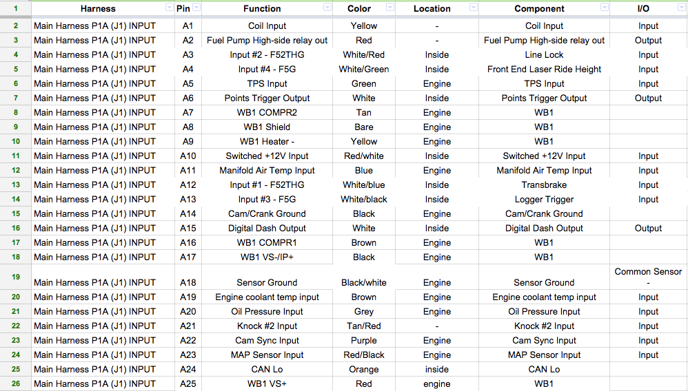
The wiring diagram made for BlownZ was made on a spreadsheet. In addition to this, it would be a great idea to sketch a diagram of the car and roughly plot everything. When it comes time to get started, everything will be mapped out.

The first, and most important do is to diagram everything. Using a navigation system is very similar to wiring because every route needs to be planned out. Without proper planning, the wiring could turn out to be one of the biggest clusters ever experienced. Mapping out where everything goes, how much supplies are needed for each and every system in the car, and where to start are crucial to begin a wiring project.

“The biggest ‘do’ and the biggest thing that I think people should take away is that a lot of people are intimated by the thought of doing a wiring job. And because they haven’t done it before, they don’t understand 100-percent of all the things that they’ll have to do. If the person doesn’t know where to start, they’re just going to start soldering stuff, or, you know, running wires and all that without a plan. That’s when they run into some really difficult decisions, and unless they know what they’re doing, they’ll get in over their head,” Jordan explained.

“You make a list of what all the components need. If you have all the information you need to make the diagram, then you have all the information you need to make the harness. If you can’t get through the diagram, meaning that if you don’t know what you need or if you don’t know where stuff goes, you need to figure that out before you start,” added Jordan.

2. Use Crimps When Vibration Or Strain Is An Issue

We all know that racecars vibrate a lot. whether they’re under load out on the track or sitting and idling, there will be vibration. There are also times when wires route through tighter places than others, causing strain. When vibration is a big issue, it is better to use crimps to make a connection, rather than soldering it. Solder is great for electrical connections, but it isn’t a true fusing of metal like an actual weld. It has the tendency to crack under vibration or strain, causing the connection to short, or disconnect completely. Remember to always plan out where your solder joints will be so that when it comes time to add them in, the area is already relieved of stress.

“We use crimps when mechanical forces are an issue. I come from the aviation world where crimps are the norm because vibration is always an issue. But in cars, as long as you can strain relieve and isolate the joint from vibration, solder joints work very, very well for a lot of things,” explained Jordan.

“The downside to crimps, most of the time, is that they’re much bigger than a solder joint. If you had a bundle of 50 soldered wires and you staggered the joints, you wouldn’t be able to tell where those splices were. But if you shaped that harness, vibrate it, or put a lot of strain on it, you’re gonna break a few of those solder joints, whereas crimps would not break,” Jordan stated.

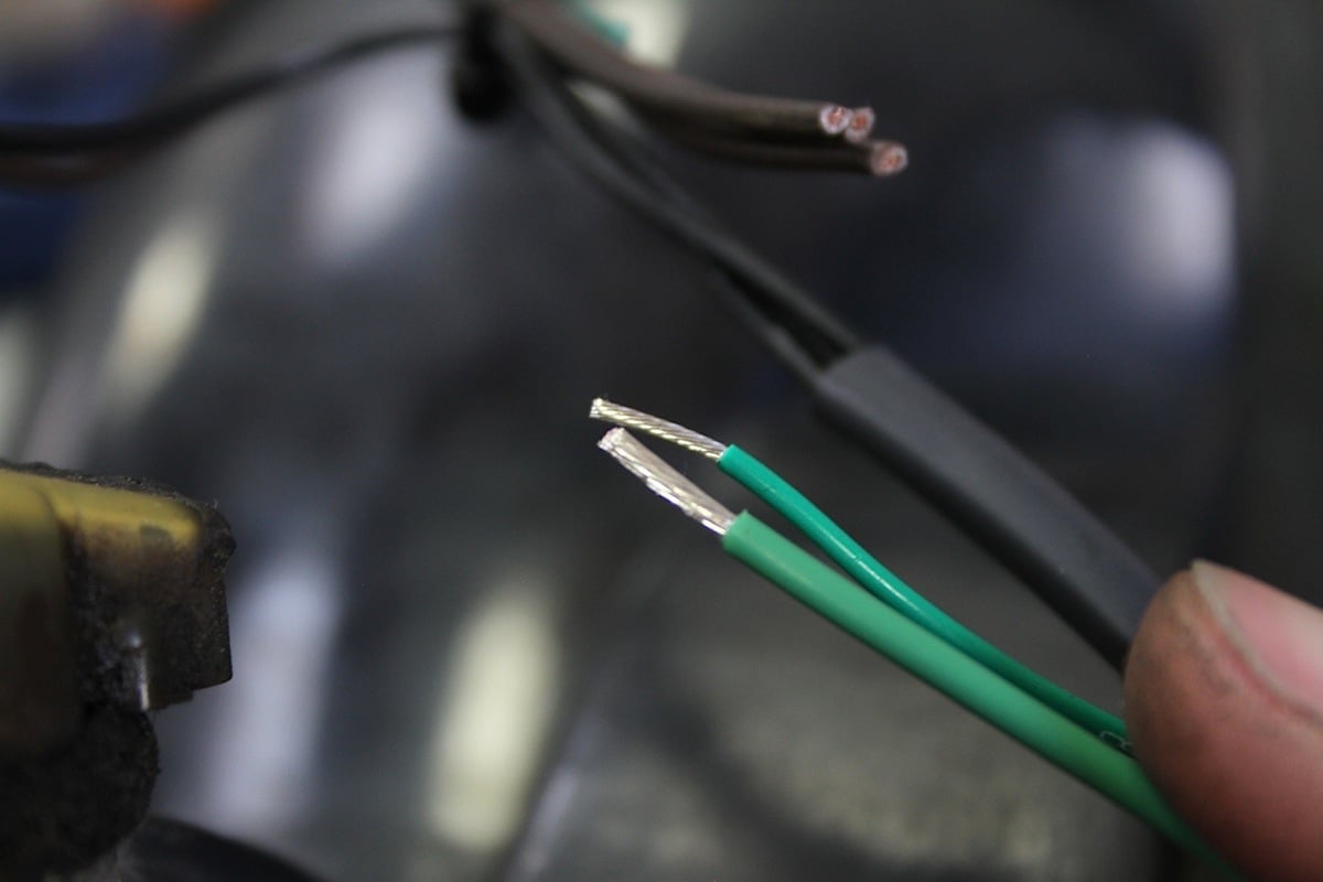
3. Stagger Your Solder Joints

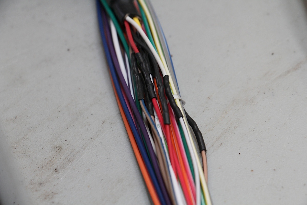
As you can see, these solder joints are staggered, meaning that the joints are not spliced in the same place. Instead, they’re offset to keep the diameter of the harness constant throughout. Our harness’ solder joints aren’t staggered too far apart due to the harness being larger in diameter. In most cases, you’ll want to solder the joints an inch apart or more.

Staggering solder joints is a very good tip for basic wiring or even for building something as extensive as a wiring harness. When there is a bundle of wires that need to be spliced, it would be ineffective to splice all of the wires in the same spot because it would create a larger diameter spot in the harness. By staggering the joints, it allows for an even diameter throughout the harness.

“Whenever you have a splice it’s gonna be a little bit thicker in that spot. If you stagger the joints, the bundle diameter stays closer to constant. You don’t want there to be one thick section and one thin section,” Jordan explained.

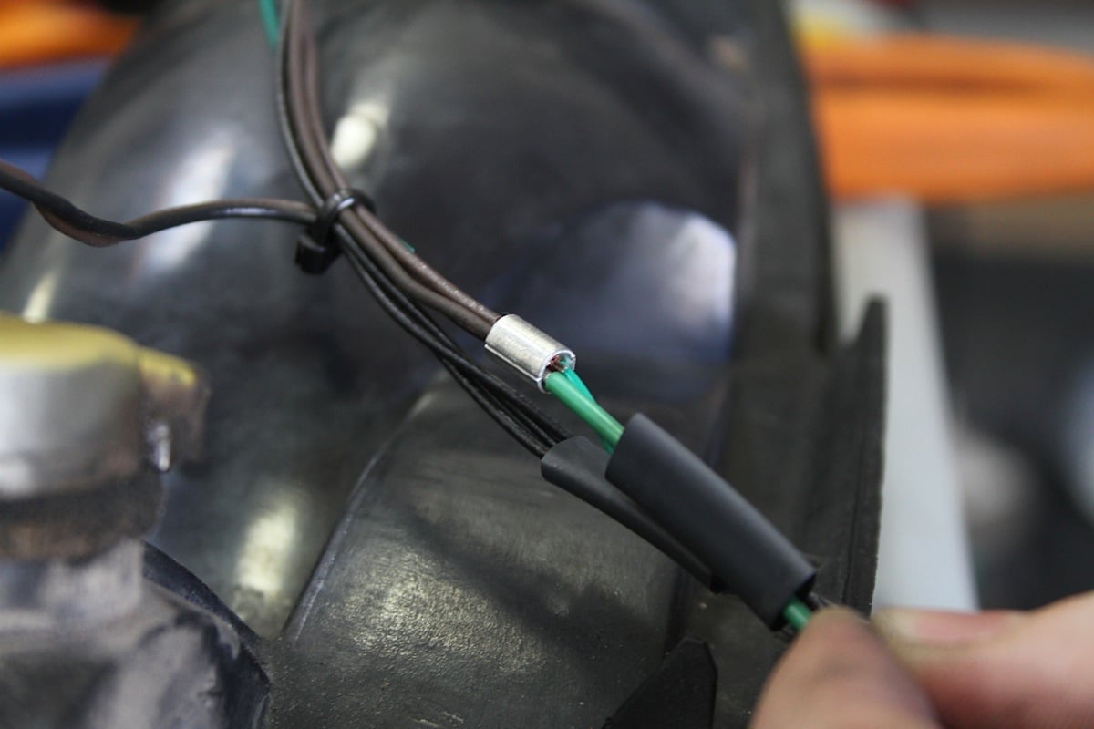
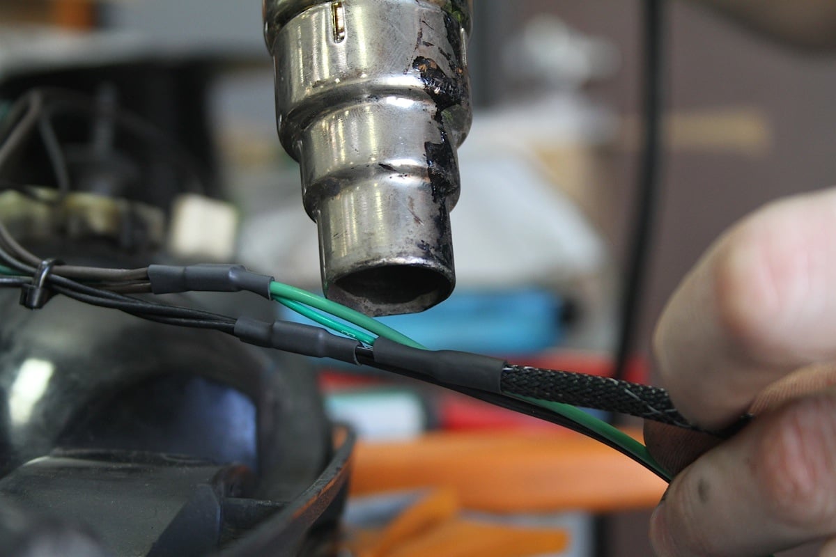
4. Strain Relief and Abrasion Resistance 

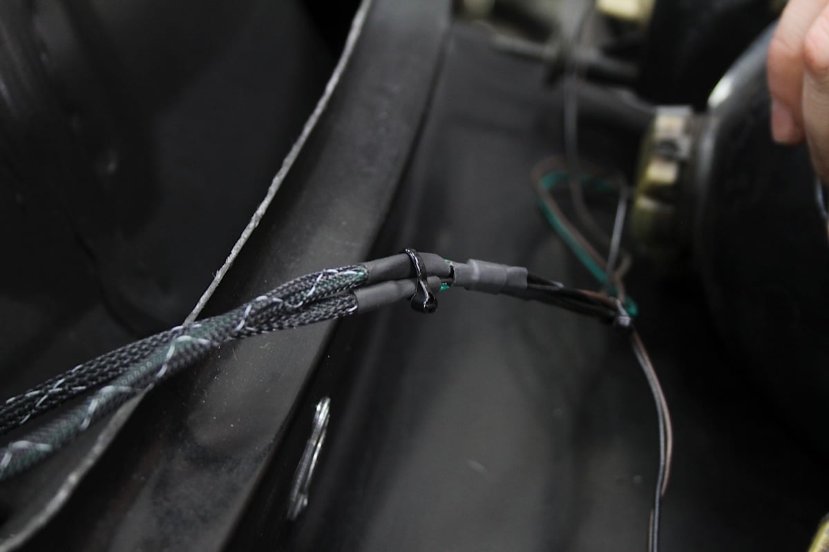
A wiring harness can be routed anywhere throughout the car. It would be in your best interest to strain relieve the harness, should any mechanical forces pull on the harness while the car is idling, under load, or even stationary. This can be done by adding some method of external support for the harness at every splice.

“Everywhere you have a mechanical force on the harness, trying to pull it apart or trying to pull it in one direction, you want to have something like a ziptie  or P-clamp so that the mechanical forces acting on your harness don’t pull it apart or vibrate it out of commission. Think of a half-inch harness that splits off into quarter-inch harnesses; you want to make sure that if you pulled those quarter-inch harnesses apart that it doesn’t rip into your half-inch harness. You’re making sure that you’re not bending and vibrating the harness at the same point over the lifetime of the harness, because the individual copper wire strains can break. That’s what zipties are for in every splice,” Jordan stated.

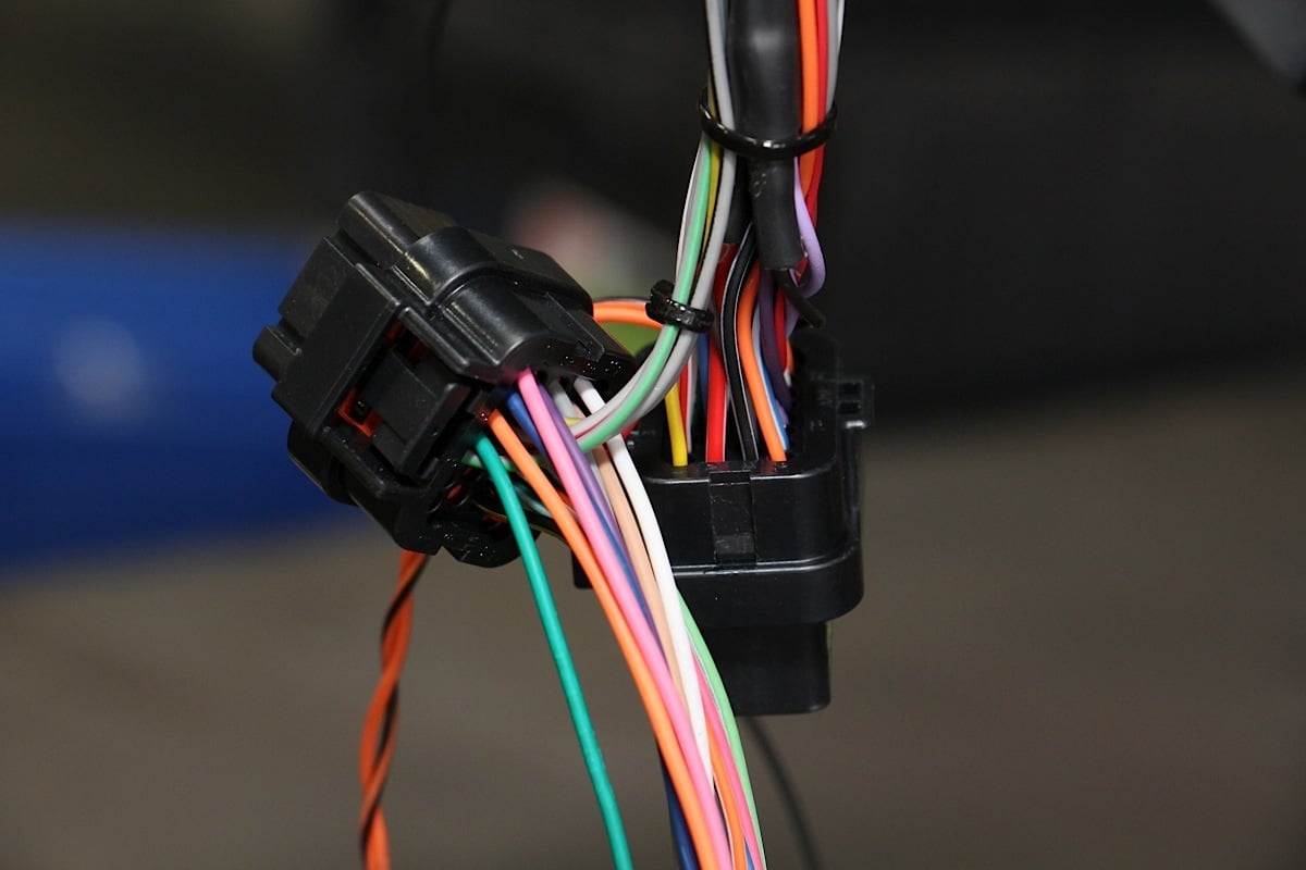
Another thing that is often overlooked is strain-relieving the wire ends where they enter other components, especially connectors.

“We strain-relieve all of the crimps where the wire enters the pin that goes into the connector. Those all have a wire crimp and insulation crimp. The insulation crimp is the part of the pin on the back that goes over the plastic, and the purpose of that strain-relief is that if you pulled the wire, it’s holding on to the insulation, not just the copper, because the copper will work-harden and break,” said Jordan.

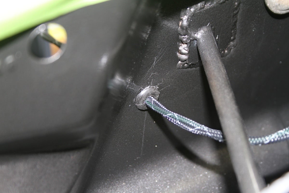
If the harness is going to be routed anywhere where the loom can be ripped, like sharp corners or edges, or through the frame or firewall, it would be a good thing to prepare the area for abrasion resistance. That can be done by using rubber grommets to protect the harness from the spot where it enters the frame to the spot where it exits the frame.

“Whenever you have a harness that passes over a sharp corner, you want prevent the harness from getting rubbed or cut. Running stuff through the frame is really cool, except everything vibrates, rattles, and gets pulled on. Putting grommets where harnesses pass through bulkheads is key,” Jordan explained.

5. Use Good Materials And Tools

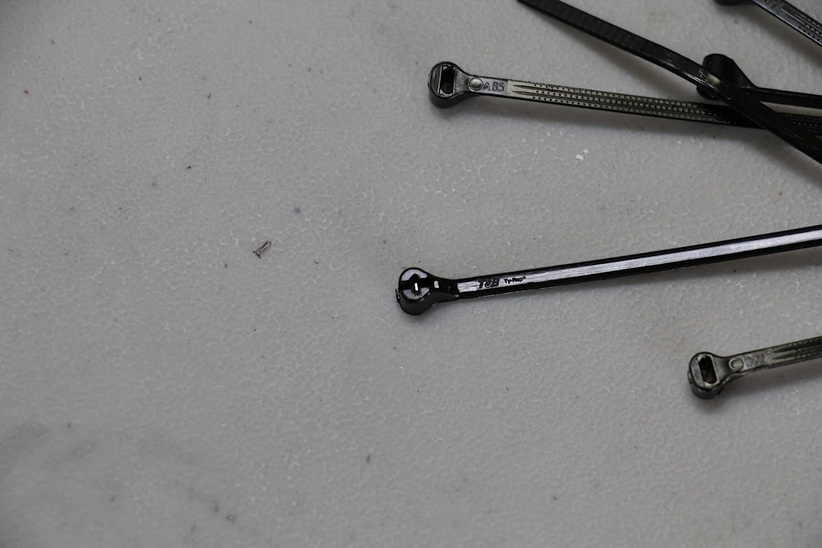
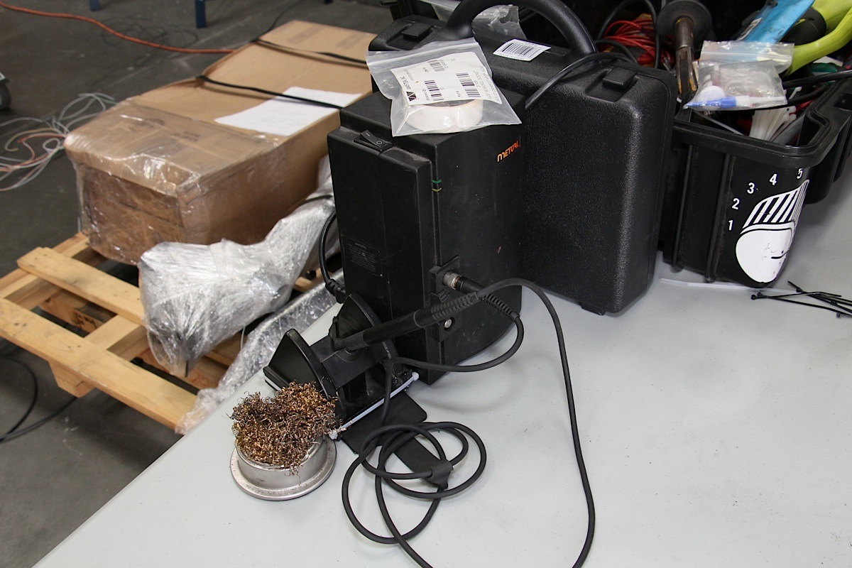
Left: T&B Ty-Rap zipties are choice for Jordan because they have a stainless steel locking mechanism for maximum strength and longer life, rather than a standard ziptie with a nylon locking mechanism. Right: Jordan’s Metcal soldering station where all of the wiring magic happens.

Knowing your business when it comes to wiring is one thing, but using good tools and good materials is half the battle. Using supplies that are tried-and-true is the way to go when tackling even the easiest of motorsport wiring jobs.

“Having good tools and materials is all relative. There’s definitely another level of materials and tools above what I use that Formula One uses. You’re not going to be doing a motorsport-level wiring job with stuff from Auto Zone. Some of that stuff might work well, but there’s a reason why professionals tend to use better tools and materials. Some people aren’t going to pay $700 for a pair of crimpers if they’re only gonna use them once, but some might pay 50 bucks for the next step down on eBay or Craigslist,” Jordan added.

Often, the step up in price from bargain no-name equipment and raw materials to decent quality stuff is relatively modest, although it can add up when wiring an entire car. Compare that to the cost of making repairs or troubleshooting, though, and it’s worth every penny.

The Don’ts:

1. Don’t Hack Or Get In Over Your Head

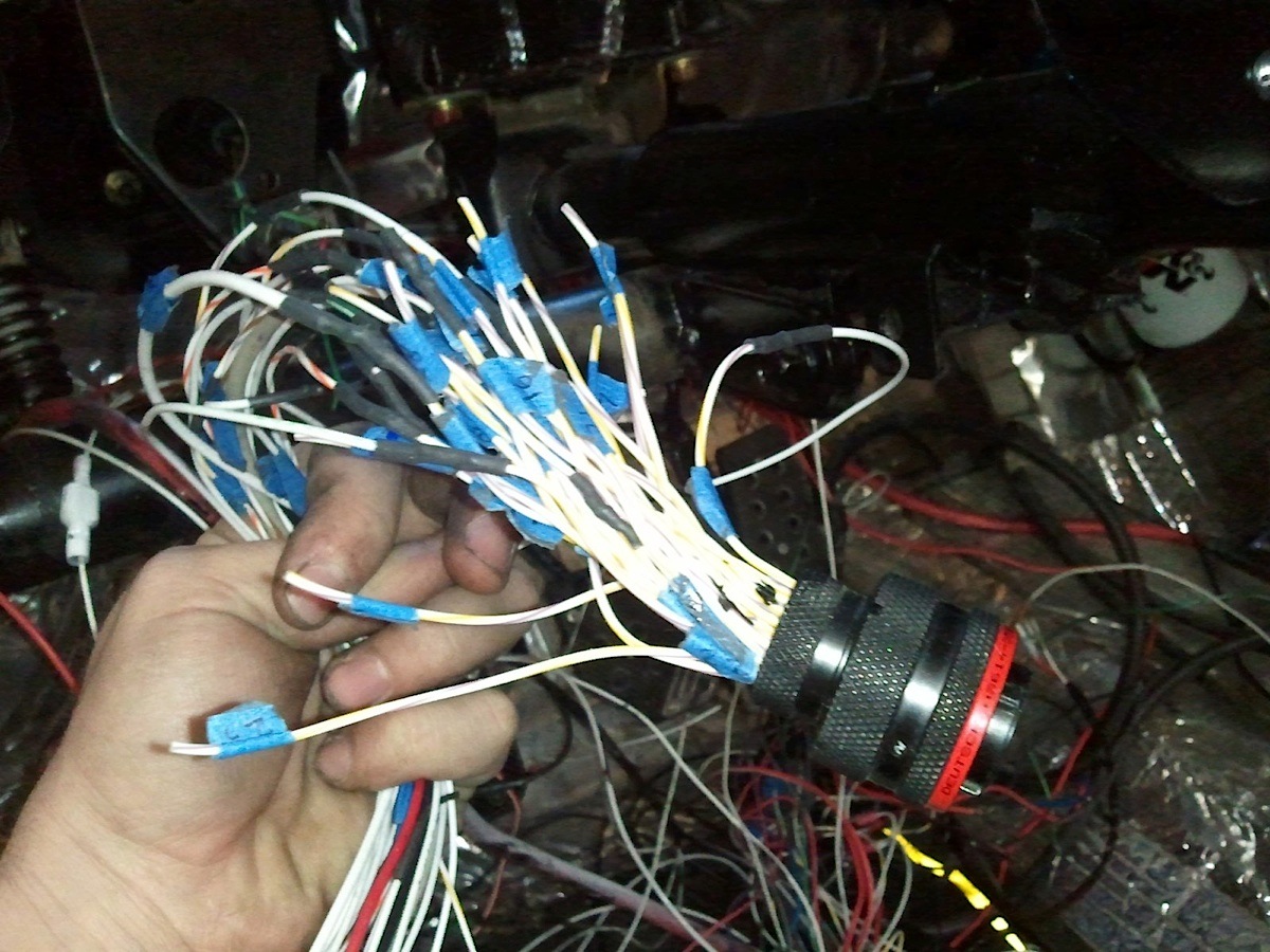
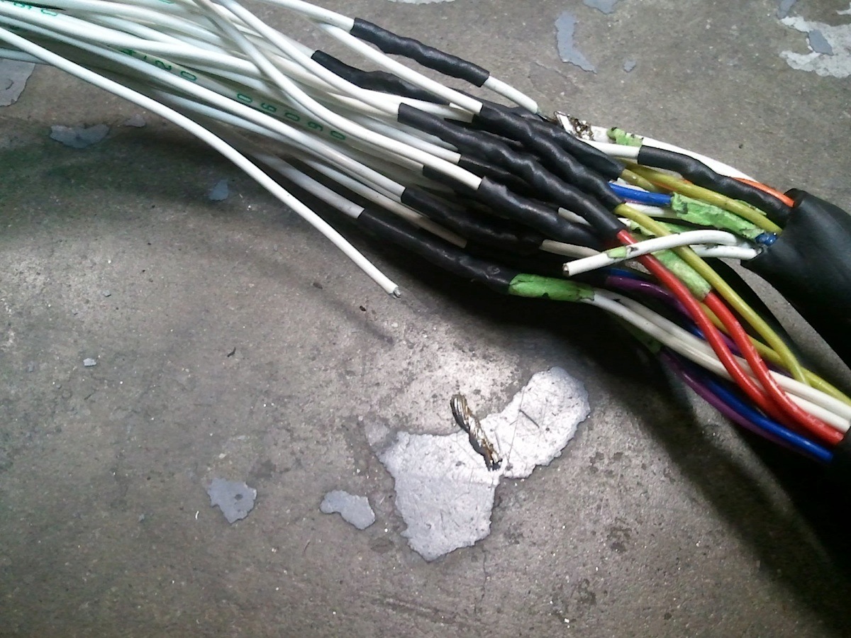
This is what happens when a lack of patience takes control and the proper steps aren’t taken the first time. You end up in over your head with a huge cluster of solder joints with no other choice than to start over. Take the time to understand what you’re working with.

The number one rule when it comes to wiring is to have patience. Don’t have the mindset to wire the car up hastily just to get it running and say you will build a nice harness later, because “later” never comes. Just do it right the first time and you will be surprised at how much time and money was saved. You’ll also have a running car!

“Build the harness and then test each part of it before you go invest a ton of money to take your car to the track. That disappointment of ‘I thought the car was working and it’s not’ is such a powerful demotivator to car fans, and that’s how cars get left sitting for the whole season. You know, like ‘ah f@&# it, I’m just going to leave it in the garage,’” explained Jordan.

Frustration leads to mistakes, and when you’re working with electrical systems, mistakes lead to fun stuff like cars not running, or worse yet, cars catching on fire. If you don’t have a good understanding of what you’re doing, stop and fill in the gaps in your knowledge before continuing the job, or bring in an expert if it’s truly beyond your abilities.

2. Don’t Wire Both Ends Then Route The Wires

This is why wires shouldn’t be soldered and crimped at both ends before routing the wire through the car. The end result is wires running everywhere, not in one concentrated harness. This is also goes back to using good materials. Twist-on wire nuts have no place in automotive wiring as they don’t cope well with vibration. Also, there is no strain relief.

This is a big one, and it’s something that a lot of people do without knowing that what they’re doing is wrong. By doing this, it’s very easy to end up with a bunch of wires running all over the place. To avoid soldering or crimping both ends before the wires are routed, simply refer back to the diagram of the electrical system you are building and you will see how everything needs to be routed.

“Something that a lot of people do is they’ll run wire run and solder or crimp the ends, and then figure out how it routes through the car. That’s how you end up with stuff that just runs all over the place. This goes back to if you have a diagram of where all your stuff needs to go. With that diagram, you’ll know that the wires that go from A to B will need to pass through there and there to get there using the routing that you designed. All of your wires will have enough length on them and they’ll go where you want them to go,” added Jordan.

3. Don’t Place Solder Joints In Areas With Vibration Or Strain

In this photo you can see the broken solder joint due to vibration and not staggering them. These can be incredibly hard to diagnose.

When a solder joint is made in an area with a lot of vibration or strain, it will easily break and cause a short or open circuit in the system it’s running to. Use crimps in these areas, as they are far more flexible than a soldered joint.

“What’s so bad about solder joints that break is when you go to pin out the harness, It’ll pin out with continuity, you know, if you’re on a continuity test on the multimeter and you’re testing from A to B, it’ll beep and read 1 ohm or 0 ohms because it does have continuity, but its broken. As soon as you try to pass some power through there, it’s going to create a bunch of resistance and your voltage is going drop because the solder joint is broken. That wire’s joint’s ability to pass power through it is now one 1/100th of what it’s supposed to be,” stated Jordan.

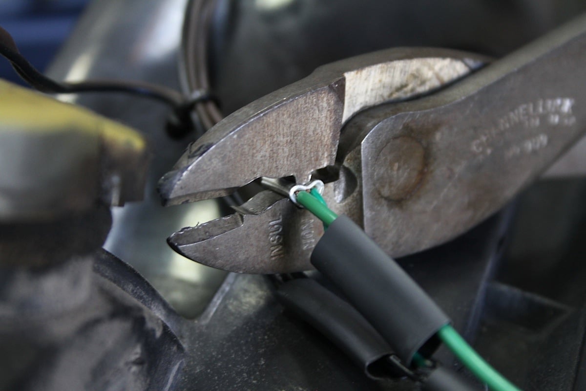
4. Don’t Use Regular Pliers For Important Crimps

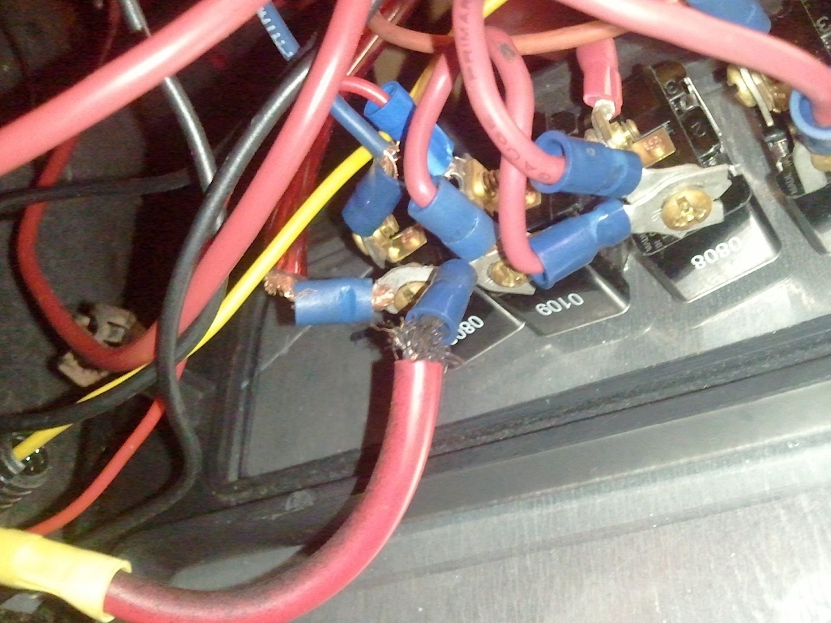
It’s obvious that these crimps weren’t performed with a proper pair of crimpers. Also, this is not the correct wire or wire size for the job, which is why the individual copper strands broke. This is exactly what you don’t want your wiring to look like when all is said and done.

The reason why it’s not good to use pliers, or any other tool not meant for the job, for important crimps in the system is because they won’t hold. It might look like a good crimp, but there is no way to tell. So, in this case, it is really beneficial to use the proper pair of crimpers for the job.

“A lot of people don’t buy good crimpers or they don’t know where to buy good crimpers, so they end up using pliers. The important thing about a crimp is that a crimp doesn’t have solder to help out with the mechanical connection between the wires. All you have is a mechanical connection that you’re able to put on these wires with the crimp. Also, there’s no way to tell when the crimp fails because it will still be touching, but it won’t be touching all the way around. It’s very hard to diagnose when a crimp fails,” Jordan explained.

5. Don’t Rush

Chances are that if you rush a wiring job, you’re setting yourself up for disappointment. Just take your time to learn what you’re working with, make a diagram, take good measurements, and everything will go together as it’s supposed to. Because it’s usually one of the tasks left to the end of a project, wiring a car often doesn’t get enough time budgeted for its completion, and builders will make the error of speeding through the process as quickly as possible to meet a deadline.

“The only way to guarantee failure is to rush.  You could have done everything else right, but if you rush your chances of having a harness that doesn’t work go way, way, way up and that’s true for anybody. It’s true for somebody that does it 5 days a week, just like its true for somebody that does it once every couple of years.  So, take your time,” Jordan added.

Positive Energy

Hopefully these tips will help a lot when it comes to wiring up your own project car. With wiring, it’s really important that a diagram is made, good materials are used, quality tools are used, and that you have quite a bit of time on your hands, as doing things right can be a very time consuming process. The last thing you’d want is for your wiring to ruin the whole project, so just take your time and understand what you’re working with before you get started.

We want to give a big thanks to Jeff Jordan of Jordan Innovations for taking the time to sit down with us and go over these helpful tips with us. And we also want to thank him for doing an awesome wiring job on our beloved BlownZ!

Posted on Leave a comment

Clearing Up Myths About E85 And Ethanol: 16 Things You Need To Know

Over the years we’ve seen all sorts of misinformation floating around the web on various forums and other social media interfaces with respect to E85 and ethanol fuels, so in the interest of education, we’ve taken some of those questions and put them into a Q&A format for you, dear reader. Without further ado, here are 16 things you need to know to maximize your E-xperience.

Q: What is ethanol?
A. Ethanol is a fuel created from the distillation of sugar. This fuel comes from renewable resources, such as corn and sugar cane. This fuel has certain advantageous attributes that make it a popular fuel for performance and racing. Currently NASCAR uses a race gasoline mixed with 15-percent ethanol, and the Indycar Series racers that initially switched from methanol to E98 subsequently converted to E85 in 2012.

Q: What is E85?
A: Anytime you see gasoline with an E prefix, that indicates the fuel contains a given percentage of ethanol. So E10 would contain 10-percent ethanol, E30 is 30-percent ethanol by volume and so on. This makes E85 a fuel with 85-percent ethanol and 15-percent gasoline. Along these same lines, E0 would indicate no ethanol is added to the gasoline.

Q: I’ve heard that ethanol is corrosive.
A: Ethanol by itself is not corrosive. E98 will likely contain an average of 0.5-percent water. This is because it is extremely expensive to remove that last bit of water. When ethanol is mixed with sufficient amounts of water, this can cause corrosion, but the effects can be minimized with easy steps such as keeping the fuel tank full when the vehicle is stored. Oddly, ethanol is also an excellent cleaner and will remove deposits often left by “bad gas.” Ethanol is often mistaken or linked with a fuel called methanol, a wood- or petroleum-based alcohol that is especially corrosive when stored in solution with bare aluminum. Ethanol is not an acid and has little effect on aluminum fuel system components.

Q: What is E85’s octane rating?
A: Gasoline is most often rated on an anti-knock index (AKI) that averages both a research and motor octane number. Premium pump gasoline (E10) is most commonly found with either 91 or 93 AKI. E85 has an octane rating between 100 and 105. You will read claims that can vary by a tremendous amount. This number can vary depending upon some complex ways that octane is measured which do not take into account E85’s ability to cool the inlet air.

As ethanol becomes a more accepted alternative fuel, you will begin to see more blender pumps that will offer percentages of ethanol like E15, E30 or E85.

Q: Can I pump E85 into the gas tank and run it?
A: If your car is a factory-built Flex-Fuel Vehicle (FFV) the answer is yes. But for a typical late-model car the answer is no without making significant changes to the amount of fuel delivered by the fuel injectors. Older carbureted cars and performance cars can be adapted to take advantage of this fuel’s outstanding octane and cooling benefits.

Q: What is the difference between ethanol and methanol? I’ve heard that methanol is nasty stuff and really corrosive.
A: Ethanol (sometimes referred to as E98) is simply no different than distilled spirits – sippin’ whiskey, if you will. The other 2-percent is gasoline, so it should definitely not be consumed. This fuel offers many of the benefits of using alcohol as a fuel with fewer of the negative side effects. Methanol is often called wood alcohol, or it can be made from natural gas. Methanol is toxic and should not be ingested. Methanol also has a lower heat content. However the BTU (heat) content of methanol is roughly half that of gasoline, which means you have to burn twice as much to make the same heat. Methanol is also more corrosive than ethanol, which is why ethanol is a better choice for street-driven engines. Indy cars prior to 2006 used methanol, converted for a short time to E98 and now run E85. NASCAR recently switched to Green E15 for the Cup cars.

Q: What is denatured alcohol – is that different from ethanol or E85?
A: Both start as ethanol, which is a spirit derived from any number of sources, the common being corn and (or) grains. Denaturing adds a small percentage of a poison like gasoline to the ethanol to render it toxic to ingest. This is done to allow its manufacture for purposes other than for human consumption. Other than the additive, it is usually straight ethanol, although our sources indicate that fuel grade ethanol has impurities like iso-butanol, which will certainly make someone very ill if consumed.

Q: Can I just increase the size of the jets in my carburetor and use E85?
A: The simple answer is that this probably will not work. E85 has roughly 25- to 30-percent less heat per pound of fuel so you need to increase the size of the jetting by roughly that much. So if the stock jetting was 75, it would require as large as 100 to 105 jets. This becomes an issue because the rest of the carburetor is not appropriately sized to meter that much fuel. It’s better to invest in an E85-designed carburetor. There are several companies that offer E85-specific model carburetors.

A quick way to measure a percentage of ethanol in gasoline like E85 is with this simple glass vial tester from Holley. Add a measured amount of water with the fuel, and mix it. The water will separate the fuel from the gasoline and display the ethanol percentage.

Q: Why does an engine require more E85 to make power compared to gasoline?
A: This has to do with ethanol’s chemical makeup. Because ethanol contains oxygen, it produces less heat for the same volume of fuel. As an example, a gallon of gasoline typically will produce 114,000 BTUs of heat while ethanol comes in at a lower rating of 76,600 BTUs per gallon. You will read estimates of 15- to 18-percent loss in mileage-per-gallon when using E85 compared to gasoline in flex-fuel vehicles (FFV). But an interesting change occurs with E85. It has a much greater cooling effect on the inlet air than gasoline and also delivers a much higher 98 to 100 octane rating. For any engine that can benefit from a fuel with a higher octane, it’s common to see a significant power improvement when using E85. This is especially true with supercharged or turbocharged engines. For naturally-aspirated, street-driven vehicles, there will be a mileage penalty with E85 compared to gasoline.

There are several companies currently distilling or refining ethanol so you’re likely to see many different logos.

Q: I’ve read that all gasoline sold in the U.S. contains 10 percent ethanol. Is that true?
A: Not entirely. However, currently 96- to 97-percent of pump gasoline sold in the U.S. is blended with what averages to 10-percent ethanol. This was part of the EPA’s Reformulated Fuel Standard (RFS) that eliminated or reduced the use of other octane-enhancing additives that were deemed dangerous. In certain portions of the country you can purchase E0 or gasoline that does not contain ethanol. However, these fuels are blended with much higher concentrations of octane improving chemicals called aromatics that increase the emission of exhaust toxins.

Q: I’ve read several magazine stories where supercharged engines really benefit from E85. Is there any advantage to using E85 for a naturally-aspirated engine?
A: Absolutely. First, E85 offers an excellent octane or anti-knock index (AKI) rated between 100 and 105 octane. This can allow increasing the static compression ratio up to as much as 13.0 to 14.5:1 and will certainly improve performance on engines even at 11.0:1. Plus, E85 reduces inlet air temperatures which improves power by cooling the air entering the cylinder. Cooler air is denser, which adds power. There will be significant tuning changes necessary when using E85 instead of gasoline, but high-compression engines can especially benefit from E85.

If you are interested in a more exact test of ethanol percentage of blending, Kent-Moore has a tool that accurately measures the blended percentage of ethanol in the fuel. You can find this listed under PN J44175.

Q: I hear one of the advantages of E85 is something called heat of vaporization. What does that mean?
A: The term most commonly used is latent heat of vaporization. What this refers to is the amount of heat required to convert a liquid—in this case E85—into a gas or vapor at a constant temperature and pressure. What this means is that when ethanol vaporizes, it pulls heat out of the air in the process, which cools the surrounding air. Ethanol has three times the cooling effect, by volume, than gasoline and four times the cooling based on BTU content. Cooling the inlet air simultaneously reduces the engine’s sensitivity to octane. This is why engines tend to knock or detonate with higher inlet air temperatures. When E85 fuel vaporizes in the intake manifold, it cools the air, making the engine less sensitive to detonation.

Q: I’ve heard that the percentage of ethanol in E85 can vary. Is there an easy way to test the actual percentages of ethanol and gasoline?
A: There are several inexpensive E85 testers on the market. Most of them merely have you add a specific amount of water into a tube and fill the rest with your E85 fuel test sample. The water will separate out the gasoline and you can read the percentage right on the side of the tube. This is a simple test that can have an error factor of up to five-percent. The more precise tools are the hand-held electronic devices that are within one-percent. There are also OE sensors that are designed to be permanently mounted in the vehicle’s fuel line. Percentages of E85 will vary most often during winter when the percentage of gasoline is increased to improve cold weather starting for Flex-fuel vehicles.

Production flex-fuel engines are designed to run on differing percentages of ethanol, requiring an ethanol content sensor in the fuel system. Several companies, including Innovate Motorsports, offer a gauge that will display the percentage of ethanol in the fuel using one of these factory flex-fuel sensors.

Q: I keep reading about E98. Why isn’t it just E100 – pure ethanol?
A: The term E98 is used as a more accurate accounting of the total amount of ethanol. For the practical purposes of using ethanol as a fuel, E98 is essentially just ethyl-alcohol or ethanol plus 2-percent gasoline so that it cannot be consumed.

Q: I’ve been told that if I put E85 in my older muscle car, I will have to use a special and very expensive PTFE fuel line. Is that true?
A: It is a good practice to replace the original fuel system in an older car when building a performance car, with the emphasis on eliminating corroded, bent, or otherwise damaged fuel line with fresh new material. While ethanol has taken the blame for much of the “damage” that has occurred from reformulated gasoline (RFG), it’s important to point out that 25-percent of US fuel contains aromatics that are also detrimental to fuel systems. Over time, it has been shown that it is these aromatics, and not necessarily the ethanol, that can cause fuel system damage. The polytetrafluoroethylene (PTFE) linings now popular for performance fuel systems is similar to what the OE manufacturers use for fuel systems today. It is not mandatory that you use the PTFE style fuel line, but it will offer long-term reliability.

Injector care when using E-fuels is important.

Q: I know that pure alcohol burns almost invisible in daylight. Does E85 also burn invisibly?
A: Pure methanol (wood alcohol) burns with a pale blue light that is nearly invisible in daylight. This may be what you are referring to. Straight ethanol, the alcohol used in E85, burns with a pale yellow flame. Under bright daylight conditions, burning E98 will be very difficult to see. Mixing 15 percent gasoline with ethanol (E85) produces a much more orange hue to the flame, making it very easy to see in daylight and therefore much safer as it relates to seeing the flame.

Q: I hear that E85 is not really E85 anymore. What is it?
A: The American section of the International Society for Testing and Measurements (ASTM) fuel standards and other regulatory rules now call out Ethanol Flex Fuel instead of E85. This allows the fuel regulations to provide the same fuel properties throughout the entire country to be anywhere from E51 to E83. If that sounds confusing—it’s because it is! The point is you will need to be aware of the fuel coming out of that yellow-handled pump—it often will not be true E85.

We hope this has cleared up some of the misconceptions and “So I heard” questions you may have related to the use of E85 and (or) ethanol in your hot rod. Thanks for reading!

Posted on Leave a comment

The Differences Between Air-To-Air And Air-To-Water Intercoolers

It’s the age old debate of which is better, air or water? Both are required for our biological survival as human beings, and both are used as a cooling medium for compressed intake charges in automotive applications. While there are benefits and drawbacks to both air-to-air and air-to-water charge cooling, what is “best” will vary greatly by application and the debate will rage on for a very, very long time.

However, before you can get in on the debate, you really need to understand how each type of charge cooling system works. For that, we turn to Jason Fenske of Engineering Explained. In his latest video, he goes over the basics of each type of system, and their pros and cons in a production application.

It wouldn’t be a Jason Fenske video without a whiteboard. This shows a simplified view of the two types of systems. On the left, the system shows an air-to-water system plumbed into the intake manifold, as often seen on positive-displacement supercharged engines, but are now being used by manufacturers on factory turbocharged applications. On the right is a turbocharged (or centrifugally supercharged) application using a more traditional (in a production application) air-to-air intercooler.

Air-To-Air

The air-to-air intercooler system is relatively simple. It uses airflow through the intercooler to remove heat from the compressed charge air. Heat is transferred from the charge (air) to the atmosphere (air) – hence the name “air-to-air”. “You have air coming in through the air intake, through the compressor, then to the front of the vehicle through the heat exchanger and then into the intake manifold,” Fenske explains of the air-to-air system.

Air-To-Water

In an air-to-water system, the heat from the intake charge isn’t removed by external airflow (at least not directly), but rather by a liquid coolant. “The air to water system is a little more complicated. The air again comes in through the intake and through the compressor,” Fenske says. “The compressed air then feeds into the intake manifold with its integrated intercooler.”

While in the production example Fenske is using – a BMW X3 M40i with the B58 engine, which uses a manifold-mounted air-to-water intercooler, much like the venerable lineup of supercharged Ford Four-Valve Modular engines, and aftermarket Kenne Bell and Whipple supercharget kits – the science and design of all air-to-water intercoolers are similar across the board, regardless of charge cooler mounting location.

In addition to the actual charge cooler, air-to-water systems have a secondary cooling system, much like a standard engine cooling system, but dedicated specifically to the intercooler. “You have a coolant which passes through the intercooler core and is then pumped through the system to a radiator in the front of the car to have the heat removed,” Fenske says.

Front-mounted air-to-air intercoolers like this one from Full Race (with the OEM intercooler in the rear) act much the same way a radiator does, except instead of cooling down your engine coolant, it cools down your intake charge, once it has been compressed. By mounting the intercooler in the front of the car, it is ensured a clear, cool supply of air.

Pros and Cons

Trying to ask which method of charge cooling is better is like asking what the best power-adder is. The answer is simply, “It depends.”

“The air-to-air system is a much simpler system. You don’t have to worry about fluid leaks; you don’t have the additional heat exchanger and the [associated] fluid plumbing. You have less weight with an air to air system as well,” explains Fenske

In an air-to-water system, once the coolant has pulled the heat out of the charge air, the heat must then be pulled out of the coolant itself. “Another big advantage to the air-to-air system is that you are only relying on heat being exchanged once. With the air-to-water, you’re relying on ambient air to get the temperature of the coolant as low as possible.”

Fenske does point out that air-to-air coolers do have drawbacks, saying, “However, you must mount an air-to-air where there is airflow, and ideally that would be in front of the engine, although you can mount it on top of the engine as well. You won’t get as much airflow, and potentially be susceptible to heat soak from the engine.”

Moving to the air-to-water system, Fenske continues, “Air to water intercoolers [in production applications] reduce the volume of space between the compressor and the intake valves, because the air-to-water charge cooler can be mounted anywhere under the hood, and not have to be routed up front into the airstream This reduces the distance the compressed charge has to travel.”

In theory, that reduction in volume and distance traveled by the compressed intake charge will not only increase engine responsiveness (reducing lag) but also reduce the potential of further heat soak by reducing the amount of time the charge is exposed to underhood heat.

Here you can see aftermarket examples of air-to-water intercoolers. On the left, a Vortech Power Cooler, which does keep the path from the compressor outlet to the intake manifold about as short as you can get with an intercooler, highlights Fenske’s argument. However, on the right, you can see a popular setup for high-power drag racing vehicles, in which the air-to-water intercooler is located in the rear seat, requiring the intake charge to travel quite a distance, and increasing the volume of tubing between the compressor outlet and the intake manifold substantially.

Racing Applications

Up to this point, Fenske has been looking at production applications. However, once you get into aftermarket forced induction and competition settings, not only is it a whole new ballgame, thanks to specific rulebooks, but also the specific form of racing can change what you are asking of the system.

For example, in drag racing, remote-mounted air-to-water intercoolers increase the intake charge system volume significantly – the opposite of what is discussed here – and since the duration of the performance window is so much shorter, the second heat exchanger can be eliminated, and ice water used, to significantly increase the charge cooling capabilities of the system.

Conversely, for a form of motorsport that gives a lot of airflow due to sustained high-speeds, like road racing, the lighter weight and simplicity of an air-to-air system may be preferable. Again, it all comes down to application, rulebook, and ultimately, personal preference. Step one to any of that is understanding how each system works, along with its strengths and weaknesses.

About the author

Greg Acosta

Greg has spent over a decade in automotive publishing as Senior Editor of Race Pages magazine. In his free time, he is a firearms instructor and volunteer in the police armory.

Posted on Leave a comment

Header Wrap: What You Should Know About Wrapping Pipes

Late-night pitchman Ron Popeil coined the phrase “set it, and forget it” when he was promoting one of his many inventions from the past few decades. While that notion may be just fine for a rotisserie chicken or a roast, it’s not exactly the best advice for your automobile. If you’re truly an enthusiast, you’re going to be under the hood tinkering with something sooner or later – even if it isn’t necessary. For us, there’s a different catchphrase: “forget it, and regret it.”

Most of us know we have to open the hood and do a good visual inspection. However, one area that doesn’t get much attention after the installation is complete, is exhaust headers. They get installed and essentially ignored unless you hear that ticking sound indicating an exhaust leak. If you choose to reduce underhood temperatures, you might even decide to put a thermal wrap on your headers. Like many other controversial topics, you can find many who are for wrapping them up, and just as many who are against it.

Rather than just sharing our opinion on the matter, we decided to reach out to the experts on both sides of this topic to find out what they say about wrapping headers. Our goal is not to start a debate to see who’s right or wrong, but to come to an understanding and give you the best advice from the experts: Moroso Performance Products and Design Engineering (DEI). We also reached out to one of the better known names in exhaust headers: Hooker.

header wrap

For some, the look of a fresh set of ceramic-coated headers is just right. But, if you want to reduce temperatures, wrapping your exhaust is one good way to accomplish that. The results are great, whether you have painted or coated headers.

Header wraps aren’t just for looks, they’re functional when installed properly. But it doesn’t stop there. Just like the vital fluids that keep your engine and transmission functioning properly, a header wrap also requires some level of maintenance and monitoring. If you use the same principle mentioned above – set it and forget it – you just might end up with more problems than solutions. First, let’s look at the different types of header coatings and what to expect once you wrap them.

Exhaust Headers And Header Coatings

When it comes to exhaust, Holley’s Hooker brand has been one of the leaders for decades, and is a name synonymous with performance. We spoke with Jeff Teel, sales and client services expert at Hooker, and first asked him to explain the various coatings you can find on headers, and which ones might be a problem for header wraps.

“Industrial chrome or painted mild-steel headers will have the greatest potential for developing corrosion beneath the wrapping,” Jeff said. Most of us have owned a set of chrome or painted headers, While they look great going on, they don’t look so great a couple of years later. The heat cycles of the headers themselves, along with changes in outside temperatures, can wreak havoc on the finish. Jeff recommended the stainless steel, saying, “It is the most robust and durable material from which to build headers, in any case.”

Whether you’re wrapping painted or stainless steel, underhood temperatures can be reduced considerably. Both Moroso and DEI recommend removing the headers to wrap them, and you can see why just looking at these ‘shorty’ headers. Working on a bench is going to save you a lot of headaches.

While you might think ceramic coated headers would provide the best protection against corrosion, Jeff explained, “Ceramic-coated mild steel and even stainless-steel headers can also be affected by corrosion. However, it will happen to a lesser degree depending on the quality or application method used for the coating, or the specific type of stainless steel used to build the headers.”

We also asked about headers that have had the proper, high-temperature paint applied correctly, such as on clean steel. Jeff told us, “The degree of how well they will hold up depends greatly on environmental and usage factors.” When asked about ceramic-coated headers specifically, in addition to his thoughts on application methods, he said, “The primary tube-to-collector connection points is the area that is usually first to show signs of corrosion if the application is of higher quality.”

It seems no matter what you do, you’re going to see some form of corrosion either on the tubes themselves, or at the welded areas. So what’s the purpose of wrapping them up if it’s just going to cause problems anyway? For that answer, we reached out to Moroso National Sales and Marketing Manager, Thor Schroeder.

Header wrap can come in various materials, including woven ceramic from Moroso (left). You have a few choices from DEI, including coated fiberglass (center) or a pulverized lava rock (right) in the Titanium series.

Header Wraps And Their Heat Control Properties

Header wraps are nothing new. Some people wrap their headers because they like the way it looks, others wrap their headers because of the tremendous reduction of underhood temperatures. Thor told us that header wraps can reduce the temperature by roughly 50-percent, and the surface temperatures can be reduced by as much as 30-percent.

What this equates to is a 300- to 400-degree drop in temperature, according to Mike Buca, DEI brand manager.

“We offer three basic material types: glass fiber, Titanium, and EXO,” said Mike. “Each has its benefits-to-cost ratio, with the glass fiber being the least expensive.” Those cost ratios increase not only in price, they also increase in heat protection. Mike continued, “Glass fiber is good for up to 1,200 degrees, while our Titanium wrap is good for up to 1,800 degrees. Our EXO wrap, which is designed for off-road use, is a glass fiber base, but it is inside a stainless-steel mesh sleeve.”

The various materials offered from DEI are also available in a couple of different colors. If you’d rather black out your headers, you can do so with the Titanium or EXO wraps.

DEI’s Titanium wrap is more pliable than the glass fiber wraps, making it easier to install. But, Mike does warn us that you have to be careful and keep the wrap tight, especially with ceramic-coated headers. “Ceramic can be a little more difficult because of the slick surface,” he said. “But, this only comes into play when starting to wrap the pipes, once the wrap is installed, it’s fine.”

“Header wrap benefits can be broken down into two major groups,” Thor said. “The first is protection. Reducing engine compartment heat protects crew members from burns and prevents starter wires and plug wires from coming into contact with hot header pipes.” With that kind of surface reduction, it could be the difference between smelling something burning, to making it back home after a cruise.

header wrap

“The second group is increased exhaust-cycle efficiency, ” Thor continued. “By retaining the heat in the header, it improves the scavenging of the cylinders by keeping the exhaust-speed high.” This very reason is why many companies offer a ceramic coating. The ceramic coating will help keep external surface temperatures lower than a painted or chrome header.

If you have ever done the burn test – where you reach in and accidentally burn your hand or your arm – then you know that a ceramic-coated header will cool down much quicker than chrome or painted tubes. The insulating properties of header wrap will help the scavenging process even more, because unlike ceramic, the material used in header wraps don’t retain heat on the surface.

Don’t Forget About Your Header Wrap

Once you’ve wrapped your headers however, you’re not done with them. There’s a bit of maintenance needed to ensure you haven’t had any abrasion that could cause the wrap to unravel or come loose. This abrasion could be from a steering linkage or other moving parts in the engine compartment. If this happens, the onset of corrosion can occur even quicker.

Should the header wrap start to unravel, Thor reminds us that a loose piece could get wrapped up in the engine’s pulley system. If that happens, you will get a rude awakening from the engine – and it won’t be pretty. That’s why you should always make sure they stay tightly wrapped. Even if it doesn’t start unraveling. “If it becomes extremely loose it will no longer be as effective as a thermal barrier,” stated Jeff.

Although Thor tells us that header wrap is designed to be installed and left on the headers, Jeff suggested it be inspected for corrosion, specifically on mild-steel headers. Inspecting headers periodically like we do with any other area of our engine is a good idea, up to and including unwrapping them to see the entire surface, and not just the weld joints on stepped headers or at the collector.

Another factor that can adversely affect the header wrap is engine fluids and oils. Thor said, “header wraps can last years, but they are affected by abrasion or being soaked in chemicals.” Those chemicals include typical oils and other fluids, as well as engine cleaners and degreasers.

After starting the wrap, a couple of ties will keep it in place and keep it snug. That will allow you to move further down each tube without having to worry about the top unwrapping. When you reach the end of the wrap, tie it up and continue with a new piece.

Wrapping It Up

If you’re going to wrap your headers, both gentlemen suggest doing so with the headers removed, or wrapping prior to header installation. Thor said, “It’s always best to wrap them on a bench if that is an option. It allows the installer to get a nice clean wrap with proper coverage around the header or exhaust.”

Another reason wrapping the headers on the bench is best is because it allows you to see the back side of the header without using smoke and mirrors, or trying to cram your noggin down into the engine compartment to see. Additionally, it makes more sense when you think about having to lean over the fender and thread the roll between the primaries.

Start the wrap at the primaries and wrap each tube indivudually until the tube connects to another tube or the collector, overlapping enough so that there are no gaps in the wrap.

It seems both of our experts agree on the purpose and benefits of wrapping headers. While they both have a different hand in the matter, we can all agree that keeping the heat inside the header will help with performance, and keeping the outside temperature lower can protect other components in the engine compartment – especially an arm or a hand while reaching down to tighten or adjust something.

Once you have reached the end of a tube, and are at the collector, the stainless-steel ties will secure the wrap to the header. Remember: if it’s slightly loose, then it can unravel, so keep it snug as you wrap the header.

Of course, the decision to wrap or not to wrap ultimately relies on the user’s preference. Thor has some strong points as to why header wraps are significant, but neither he nor Jeff were in favor or against wrapping the headers. If you want to find out more about wrapping headers, reach out to Moroso Performance Products or DEI and let them know how you use your car and what type of header you have installed. If you’re planning on wrapping a new set of headers, check with Hooker Headers.

Posted on Leave a comment

Answers On The Second Ring: The Science Of The Second Piston Ring

Since the invention of the metal piston ring at the start of the industrial revolution (which, you could argue, finally made steam power practical), there’s been constant innovation and improvement in cylinder sealing technology for these seemingly simple parts. The ring package has three primary goals: Keep pressure confined to the combustion chamber on both the compression and power strokes, transfer heat from the piston to the cylinder walls where it can be removed via air or liquid cooling, and control lubrication to limit oil consumption and unwanted emissions.

While it’s easy to look at the top ring or the oil ring at the bottom and intuitively understand their contribution to meeting these objectives, the second ring is more of a mystery. What’s it supposed to be doing, and why is it necessary? How do the materials used and the physical properties of the second ring affect performance? To answer these questions, we turned to Wiseco Senior Technical Account Manager Alan Stevenson.

Under Pressure

For our first question, we asked Stevenson whether the second ring had a role in containing compression or combustion gasses. “There was a time when bores were so bad in terms of surface finish, roundness, and so on, and ring materials were a lot worse, so that pistons used to have four rings; two for compression sealing, one for scraping oil, and one for pumping oil,” Stevenson explains. “The terminology hasn’t kept up with the technology. Referring to a contemporary second ring as a compression ring is a misnomer.”

So what’s the contribution of a modern second ring to combustion chamber sealing? Per Stevenson, “Negligible. There have been SAE papers published that prove how enlarged second ring gaps actually increase top ring sealing and power. Combustion sealing is 100-percent the top ring’s job.”

Note the subtle hook shape at the edge of the ring. This is a Napier-style second ring and that “hook” helps it pull oil off the cylinder wall as the piston slides down the cylinder bore.

Combined with other piston features, the second ring’s role in this respect is to keep the pressure in the crevice space between it and the top ring as low as possible, giving any blow-by that makes it past the top compression ring a way to quickly escape to the crankcase.

“An accumulator groove works in concert with larger second-ring gaps,” Stevenson explains. “In short, there will always be some combustion pressure leakage past the top ring due to secondary piston motion and cylinder crosshatch. Any pressure that makes it past the top ring tends to get trapped between the top and second ring, which then pressurizes the top ring from underneath which leads to ring flutter (especially at high RPM).”

“The accumulator groove creates additional volume which decreases pressure. This is where Boyle’s law is applicable; volume and pressure have an inverse relationship, so increasing volume of the chamber decreases pressure. Coupling this with larger second-ring gaps provides a smoother transition of the trapped gas out of that space and reduces top ring flutter.”

Because the second ring is specifically intended NOT to be a pressure seal, it’s often constructed quite differently from the top compression ring. “Many top rings have inside diameter bevels that cause them to twist opposite of the forces acting upon it in order to help keep it flat in the groove for better sealing,” Stevenson says. “Second rings have a bevel opposite to that, so they actually twist the wrong way to help sealing.”

While the oil rings do the brunt of the work “pumping” oil away from the cylinder wall face, the second ring plays a vital role scraping it off the face of the cylinder.

The Heat Is On

Having established that the second ring is most definitely not there to provide compression or combustion sealing, let’s look at the second main objective of the ring package: transferring heat out of the piston and out to the cylinder walls, where it can be managed by the cooling system.

It might seem like the relatively tiny amount of contact the rings make between the piston and the bore couldn’t possibly be a significant route for heat conduction, but it turns out to be the major provider. Per Stevenson, “There are many variables here, but the rings transfer about 70-percent of combustion heat from the piston to the cooling system.”

The remaining 30-percent escapes via other routes, like radiation and convection cooling of the underside of the piston to the air inside the crankcase, conduction cooling through contact between the piston skirt and the cylinder bore, and heat carried away via oil splash from crankshaft windage. Some engines even employ oil squirters at the bottom of each cylinder bore that direct a spray of lubricant at the underside of the pistons specifically to aid in cooling.

As rings continue to shrink in dimension to reduce friction, materials and manufacturing becomes far more critical. Carbon steel is the material of choice for most performance applications and offers robustness and durability far exceeding earlier, thicker rings.

Other sources of heat transfer notwithstanding, the ring package handles most of the load when it comes to keeping the piston at an acceptable operating temperature. Stevenson further breaks down the previously mentioned 70-percent of total piston heat, “The top ring transfers 45-percent, the second ring 20-percent, and the oil ring 5-percent,” says Stevenson. While the second ring definitely plays its part in this critical task, it’s still not the ring’s primary reason for being there.


Oil Control For The Win

As it turns out, the second ring has a lot more to do with lubrication control than the “oil ring” beneath it. “The second ring is what scrapes the oil,” Stevenson explains. “The oil ring is what gathers it and pumps it away from the cylinder walls via oil return holes in the oil ring groove.”

The second ring’s main function is to continuously remove excess oil from the bore — as the crank rotates, oil escaping from the pressure bearings on the rod big ends is constantly thrown up behind the piston, coating the walls of the bore. On the downstroke, the second ring and the oil ring work in concert to clear all but a tiny amount of oil and return it down the bore to the sump.

“The top rings will always receive latent lubrication by oil trapped in the cross-hatch of the cylinder walls,” Stevenson says. It’s that microscopic texture on the bore that retains just enough oil to keep friction between the ring package and the cylinder wall to a minimum, while the second ring prevents too much oil from making it up past the top ring and into the combustion chamber.

Thinner piston rings are far more likely to be damaged during installation than older-thicker rings. Using a tapered ring compressor should be considered an absolute necessity when building a late-model engine.

Theory Into Practice

Now that we understand each ring’s purpose in the package, we can see why different specific materials and ring cross sections are often used for the top and second rings. “The demands and intended function of the top and second rings are different, for sure, so the materials often are as well,” Stevenson continues.

“The overall best top ring material is steel. Now, granted, some steels are better than others, but as rings get smaller and specific output increases, the demands on the top ring (which sees the most abuse) are highest.”

Move down a groove on the piston, and the different job being performed places lower demands on the material being used. “Many second rings in racing engines are still cast iron or ductile iron. The second ring is not under enough stress and temperature to necessitate steel,” Stevenson explains.

Setting the proper ring gap is paramount to achieving the desired engine operating characteristics. In any performance application, the second ring gap should be larger than that of the top ring to allow blow-by to escape and prevent ring flutter from upsetting the top ring’s seal

The shape of the ring profile also has a significant effect on how efficiently it removes oil, as well as how much friction it introduces, and both the interior and exterior diameters have a role to play. “Bevels are on the inside diameter of the ring and dictate the direction the ring twists to aid in scraping,” Stevenson says. “Taper, Napier and steps are all variations of the outside diameter shape.”

Viewed in cross-section, a beveled ring has one edge of the inside diameter cut at an angle, as Stevenson points out, this encourages the ring to dynamically twist in the groove as it moves down the bore and focus additional pressure on the outside corner — in order to more efficiently sweep excess oil away.

As the piston moves down the bore, the second ring “scrapes” the oil from the cylinder wall, both providing lubrication and keeping oil from entering the combustion area of the engine.

The goal with all these profiles is to concentrate contact into a narrow band to increase the efficiency of the scraping action. As the name implies, a tapered outer profile is narrower at the top than at the bottom, while a stepped ring profile has what looks like a notch in the cross-section, oriented toward the direction of travel on the downstroke.

A Napier ring, named for the famed British D. Napier & Son engineering firm that originally developed the profile, is actually undercut at an angle or even hook-shaped on the outside diameter, further decreasing the contact area and providing space for scavenged oil to escape, away from the cylinder bore. “In order, the most efficient scraper is Napier, followed by step, followed by taper. Run a Napier if it’s available in your bore size and suits the groove in the pistons,” Stevenson concludes of second-ring face shapes.

Gas ports are another way piston designers can manipulate how rings work. By allowing combustion pressure to access the backside of the top ring, they increase ring seal increasing power while reducing friction on the other three strokes.

Application Dictates the Details

What kind of a combination you are running will also influence the optimum choice for your ring package, including the second ring. “Thinner second rings are more prevalent in dry sump engines pulling gobs of pan vacuum,” Stevenson advises. “Naturally aspirated with no vacuum help, the ring should usually be 1.5mm or larger, while forced induction should err towards even-larger 1/16-inch rings.” Because crankcase vacuum helps ring seal across the board, it’s possible to get the desired results without working the second ring quite as hard.

“Of course, this is all relative to bore size; you can almost think of it as a ratio of ring size to bore size,” Stevenson cautions. “A big boost four-cylinder engine will control oil just fine with a 1.2mm ring, while a 4.600-inch-bore big-block would be happier with a 1/16-inch ring. There are also substantial variables in crankcase efficiency when it comes to oil control. Modern engines with deep-skirted blocks, segmented oil pans, windage trays, and crank scraping/scavenging all have an effect on how much oil is thrown up into the cylinders. The more oil present, the harder the second ring’s job is.”

As you can see, second ring design and engineering is a complex subject, but fortunately, the experts at Wiseco have the collective experience in all forms of high-performance engine builds to provide you with sound advice for your particular needs. While we can’t cover everything in a single tech article, we hope that what you’ve learned here will help you to better understand the “why” behind a ring package’s specifications, and take full advantage of the knowledge on tap from Wiseco’s staff when putting together your own combination.

As with any other engine component, there are tons of different styles and ring materials that are suited to unique applications. Consulting an expert is always the best way to match rings to your engine build.

ed. note: This article was provided by Wiseco Pistons, and we felt that the editorial merit was worth sharing it with you. 

Posted on Leave a comment

Five Pro Tips For Effective Brake Bleeding For Reliable Track Use

One of the first and certain most necessary upgrades to any car, truck, or SUV headed for a track event is replacing the OEM brake fluid with one that can tolerate much higher temperatures without boiling. Upgrading fluid and bleeding brakes is an immensely important upgrade because driving at speed around a track adds an enormous amount of heat to the braking system, especially the rotors and calipers.

Why Air Is Bad

And when the brake calipers get hot they transfer that heat to the brake fluid. And when OEM or standard replacement brake fluid gets hot, it’s more likely to boil at a lower temperature, releasing air into the system. This is bad because air compresses very easily (which makes it great for tires, but bad for brakes). In this circumstance, when you squeeze down on the brake pedal, it goes mostly or even all the way to the floor because you’re compressing air rather than transferring braking force through the hydraulic fluid.

You might remember Pascal’s Law from school, whereby when there is an increase in pressure at any point in a confined fluid, there is an equal increase at every other point in the system. That’s why we use fluid to actuate the brakes on our cars.

It’s virtually impossible to drive in a consistent manner and improve your skills when the braking system is erratic; especially when a situation or even an accident can be avoided for around $60 in new racing brake fluid and less than an hour’s worth of your time.

How Air Gets Into Your Braking System

According to Anne Marie Helmenstine, Ph.D., a former research scientist for the US Department of Energy, explains where the problem lies. “A hygroscopic substance is able to adsorb water from its surroundings. Typically, this occurs at or near ordinary room temperature. Most hygroscopic materials are salts, but many other materials display the property [which is why table salt and sugar get lumpy on humid days – ed.]

“When water vapor is absorbed, the water molecules are taken into the molecules of the substance, often resulting in physical changes, such as increased volume. Color, boiling point, temperature, and viscosity can also change. When water vapor is adsorbed, the water molecules remain on the surface of the material,” Dr. Helmenstine writes.

So if water and air in the brake fluid are bad things, why is brake fluid formulated to absorb moisture in the first place? Good question. The decision was made many years ago that to reduce the risk of brake lines rusting through from the inside, which is nearly impossible to spot, it’s better to trap any atmospheric moisture that gets into the braking system in the fluid itself. The fluid is much easier to change than steel brake lines and it helps to avoid catastrophic failure. There are pure race fluids that have no hygroscopic (not hydroscopic, BTW) properties, but in order to meet DOT standards for use on the street, a high-performance brake fluid needs to maintain its hygroscopic qualities.

End of Science Class. Please move quietly to your next period class.

Our race trailer has a bucket packed with everything we need to bleed the brakes on our Honda Challenge race car: a 10 mm wrench for loosening the bleed screw, fresh bottles of DOT 4 high-temperature racing brake fluid, a bottle with a cable on it to hang off a wheel stud and catch fluid, and a clear tube to go from the bleed screw to the bottle.

Tip One: Use a Brake Fluid That’s Formulated For Track Use

The type of racing brake fluid required for track day use isn’t something you will find on the shelves of your local auto parts store. You’ll need order ahead of time well before your track day. With Amazon carrying many of these fluids, there’s no longer an excuse for not getting your brakes ready on time. Really good racing brake fluids, like Performance Friction Corporation’s PFC665 or Hawk Performance’s HP520, are readily available online.

PFC Brakes’ RH 665 racing brake fluid has a dry boiling point of 617 degrees. In contrast, standard DOT 3 brake fluid is rated to 400 degrees, which a car on a race track with stock brakes can easily exceed.

I spoke with Chris Dilbeck, who is the NASCAR and Short Track Sales Manager for Performance Friction Corporation (PFC) Brakes, and he stated that the only way to maintain a stiff brake pedal is with a good racing brake fluid. “Our RH 665 racing brake fluid has been tested by Porsche and numerous racing teams,” said Chris. “Our fluid is often compared to Castrol SRF for its similarity in performance, however our fluid is only $29 per bottle, where Castrol SRF goes for about $70 per bottle.”

Racing brake fluid is certainly more expensive than DOT 3 fluid from your local parts store but due to the level of heat a brake system sees during a track session, which can be over 1,000 degrees Fahrenheit, it’s a no-brainer that all of the hydraulic fluid in the braking system for a car driven on race track should be replaced with racing fluid.

To know how hot our brakes run during race conditions we use Genesis heat paint on the rotor. The red paint turned to yellow, which meant our brake rotor hit 1,076 degrees Fahrenheit. The fluid inside the caliper wouldn’t quite see that high of a number, but it certainly made us realize how important high-temp fluid is.

Tip Two: Proper Set Up 

Here is how to prepare yourself, your tools and equipment, and your car to remove all of the old brake fluid out of the system using a simple process that doesn’t require any engineering skills or special tools:

PREPARATION STEP 1:

Put your car on four jackstands (the same height) or put the car on a lift (where the chassis is lifted, not the wheels)

PREPARATION STEP 2:

Remove all four wheels/tires and locate the brake bleed screw on each brake caliper.

PREPARATION STEP 3:

Locate the master cylinder (under the hood) and open the cap. Have your new racing brake fluid bottle (or bottles, depending on the volume of your system) ready to go. You will need a razor blade to open the seal on the top of each bottle; the bottles are nitrogen filled.

PREPARATION STEP 4:

Find a friend. This is a two person job. Sorry, your dog can’t help you here.

PREPARATION STEP 5:

Put the friend in the driver seat and tell them their leg is going to get tired, but not to complain, because nobody cares.

You don’t need any special tools to bleed brakes. We made this brake fluid catch bottle with a used water bottle and some tubing. Works great.

Pro Tip 3: Bleeding the Brakes

BLEEDING STEP 1:

Go to the furthest brake caliper away from the master cylinder (usually the right rear). The goal here is to push as much of the old hydraulic fluid out of the system so the further away are from the master cylinder the better. Bring the correct size end wrench or flare nut wrench to loosen the brake bleed screw. Also bring your brake fluid catch bottle and a rag. Rags and a spray bottle of brake cleaner are handy through this oftentimes messy process. If this is the first time you’ve bleed the brakes and you’ve never cracked the bleed screw before, be extra careful as it could be quite stuck. Make sure you’re using the proper size box end wrench for the best distribution of force as you don’t want to strip the bleed screw.

BLEEDING STEP 2:

Place the end wrench or flare nut wrench over the brake bleed screw and then place your clear tubing over the nipple of the brake bleed screw. This should be a tight fit where no air can seep in. Have your friend slowly, gently push on the brake pedal. Do not pump! Give the wrench a quick hit counter clockwise.  You don’t have to turn the bleed screw much, just enough so that fluid begins to travel through the tube into your catch bottle. As this occurs your friend in the driver seat will feel the pedal go to the floor. Once he or she hits the floor, lightly tighten the bleed screw and tell your friend to “release.” You are going to do this process over and over again until you see fresh new fluid coming through the lines.


BLEEDING STEP 3:

It is important during Step 2 that you continually fill the master cylinder. You DO NOT want this to go dry while you are bleeding the brakes as you will add air into the system, which we’ve already learned is a bad thing. Neither the person pushing on the brake pedal nor the person at the brake caliper can see the master cylinder draining as you bleed the system. You either need another friend (three-person job) standing over the master cylinder pouring in fluid or you need to take small breaks and check the master cylinder fluid level height and make sure it always has sufficient fluid in it.

BLEEDING STEP 4:

Here is the work flow and commands our team uses as we go through this process:

The person at the brake caliper yells out, “Pressure!”
The person on the brake pedal presses on the brake and says, “Pressure!”
The person at the brake caliper slightly loosens the brake bleed screw and watches the fluid pour through the tube and checks for air bubbles.
When the person at the brake pedal feels the pedal hit the floor they yell out, “Floor!”
The person at the brake caliper then tightens the brake bleed screw. Once it is tight he then yells out, “Release!”
The person at the brake pedal slowly releases their foot from the pedal and it comes up. They yell out, “Released.”

Then the person at the caliper starts the entire process over again when they say, “Pressure!” Repeat, repeat, repeat. Fluid gets pushed through the system and the helper’s leg gets sore.

For your friends who have never driven a stick shift, remind them to press on the middle pedal. If they push on the clutch pedal, this brake bleed project is going to literally take forever.

BLEEDING STEP 5:

Once you see fresh fluid and no air bubbles coming through the line you are about ready to move to one of the other three brake calipers (usually the left rear, whichever next one is farthest from the master cylinder). But before you move, to complete the bleed on the brake caliper you started with, on your last bleed, you are going to try and close the bleed screw and catch the brake pedal as it is coming halfway down, before the person inside the car yells, “Floor.” This way you know for sure no air sucked up into the bleed screw before you get the chance to tighten it. Now it is time to move on to the next caliper.

BLEEDING STEP 6:

Repeat steps 3, 4, and 5 (remembering to check the fluid in the master cylinder constantly) until all four brake calipers are bled and only clean fluid with zero air bubbles is visible in the tube at the bleed screw.

Look at the routing of your brake lines when deciding which brake caliper is the furthest from the master cylinder. On our Honda Challenge race car our left front caliper is directly under the master cylinder (theoretically the closest caliper to the master cylinder), however due to the routing of the brake lines (the lines go from the master cylinder across the bulkhead and through a T and then back across the bulkhead into the left front caliper) the left front caliper is further away (hydraulically speaking) than the right front caliper. We do our right front caliper last (because is has the shortest lines connecting it) while bleeding brakes.

Our brake bleed kit bucket is perfect for keeping all of our tools in one spot, keeping the trailer clean, and it is also a great stool for sitting on during bleeding.

BLEEDING STEP 7:

Ensure all of your brake bleed screws are tight and clean them with brake cleaner and a rag. To check for fluid leaks have your helper press the brake pedal as far down as it will go while you inspect to confirm all the bleed screws remain dry. Ensure the master cylinder is topped off and close the cap on the master cylinder tightly. Replace wheels/tires, torque your lug nuts to the correct specifications and put the car on the ground.

Congratulations, you have just flushed your entire brake system with good performance brake fluid and you are off to the races, literally.

We label each bottle of brake fluid when it comes into our shop based on the date it hit the shelf, and later the date the bottle was opened. This helps us determine how old an open bottle of half-full brake fluid is. Once the bottle is unsealed its hygroscopic qualities start absorbing water from the atmosphere.

Pro Tip 4:

Most racing teams will bleed just what fluid is in the brake calipers after a track session or a race weekend. The process is exactly as explained above only the entire system isn’t flushed, instead only what small amount of fluid was in each caliper (the location where the fluid receives the the most heat during track duty) is bled out.

Chris Dilbeck of PFC Brakes agrees with that methodology, “After a full flush, we recommend at least one hot bleed after a session to ensure any air is out of the system. If the pedal remains stiff after a race, then the brakes don’t need to be bled. But if there is any alteration in pedal feel then it would be time to bleed them again.”

Pro Tip 5:

Our team keeps all of our tools and fluid in a brake bleed kit bucket to keep messy brake fluid away from other tools in the trailer. You can also use the bucket as a set while opening and closing the bleeder screws, If we come across a master cylinder that has really black old ugly fluid in it, we will use a syringe to take the fluid out of the master cylinder instead of pushing all of that bad fluid through the entire hydraulic system (then we refill the master cylinder with new fluid and start the bleeding process). We use rubber gloves while doing brake bleeds and normally use the three-person method to knock the job out quickly (one person on the caliper, one person on the brake pedal, and one person filling the master cylinder).

WARNING: Brake fluid is highly corrosive to vehicle paint so be careful not to let it touch your finish, even if it is transferred from your gloves. Keep rags handy. Don’t say we didn’t warn you.

After every session for Double Nickel Nine Motorsports, the race cars go up on four jack stands, are inspected and, if the brake pedal is at all soft, have the brakes bled.

Bleeding brakes is part of every professional and amateur race team’s processes and they use only the finest high-temperature brake fluids. The process is simple and inexpensive, which is why anyone thinking of taking their car out to a track day should certainly go through the procedure of upgrading its brake fluid. Have fun and remember the words, “Pressure, Floor, Release” over and over and over again. And the person pressing on the brake pedal, yup, that is going to be one sore leg.

Posted on Leave a comment

Exhaust Gas Temps, Turbos, Turbo Shields and Making Power


ABOVE:An unshielded turbo means you’re leaving a lot of horsepower and turbo efficiency on the table. Increased turbo lag, lower max boost and increased underhood heat are all negative effects of an unshielded turbocharger.

You’ll see us talking up using Heatshield Products exhaust wrap and/or insulation to keep more heat in your exhaust system for multiple reasons. First is to cut down on the amount of heat the exhaust system radiates, which can increase underhood temperatures and interior heat; the exhaust pipes running under the floor will heat the floor and transmit that heat into the passenger cabin. Second, keeping more heat in the exhaust system helps increase performance, especially in turbocharged applications. You may be wondering, how does it increase performance?

With a gas or diesel engine, exhaust gas temperature (EGT) has a direct correlation to engine performance and health. Understanding EGT can be a tuning tool (especially for turbocharged applications) and assist in wrapping your headers and exhaust with an effective thermal barrier or insulation for solid performance benefits. EGT directly relates to exhaust gas velocity, in that as the temperature rises, the exhaust gas moves at a higher velocity. With an internal combustion engine (gas or diesel) the EGT will rise as the engine makes more power or as the air/fuel mixture leans out. In the case of a lean condition with the engine, an EGT that is too high can lead to major detonation and cause severe engine damage. Back in the 1970s and the era of carburetion and tightening emissions standards, the factory would tune engines to run as lean as possible to heat up the catalytic converters faster so that they could quickly perform their intended purpose and also to burn up as much as possible in the combustion chamber to reduce the amount of fluorocarbons and other pollutants left form the combustion process.

What does a safe higher EGT (meaning the air/fuel ratio is within optimal parameters) mean in a normally aspirated engine when it comes to better performance? As the EGT climbs and raises exhaust gas velocity for each cylinder, exhaust gas scavenging increases. More spent gases get sucked out of the combustion chamber while the exhaust valve is open. The more spent gasses that can be removed before the exhaust valve closes, the better the next combustion cycle will be as a fresh fuel/air charge is brought into the cylinder.

With a turbocharged engine, increased EGT helps on multiple fronts. The first is the same as with the naturally aspirated engine: getting all the exhaust gasses out of the combustion chamber for a better burn when combustion takes place. Second, with increased EGT, the turbocharger spools up to create boost much faster and also cuts down on turbo lag. This is from the increased velocity of the exhaust gasses, thanks to the higher EGT. The third benefit of the higher EGT is that with increased exhaust gas velocity, the turbo can spool higher and create more boost, leading to an increase of horsepower once the wastegate and blow-off valve are tuned accordingly for the increased boost.

It’s easy to keep more heat in the exhaust system to help boost the EGT. Ridiculously easy. Start with the turbo itself. A proper turbo heatshield on the exhaust side will help insulate the turbo housing to keep more heat in and boost the EGT. There’s also the added benefit of cutting down on the amount of heat the turbo radiates underhood, which lowers underhood temps and the negative affects of things getting hot under the bonnet. There are multiple options from Heatshield Products when it comes to turbo heat shields, including a DIY turbo shield kit for odd sized/shaped turbochargers.

Heatshield Products Lava Turbo Shield             installed on the BroDozer monster truck

ABOVE: Adding a turbo heat sheet like the Lava Turbo Shield pictured above helps keep significantly more heat inside the turbo housing to increase EGT and exhaust gas velocity that decreases the time it takes the turbo to spool up and start making boost, along with reducing the amount of heat the turbo radiates underhood or under the vehicle (if the turbo is remote mounted). You can also see where the exhaust pipes feeding the turbo have been insulated with Heatshield Armor for the same reasons. This particular Lava Turbo Shield is mounted on Heavy D’s BroDozer monster truck. A true testament to Lava Turbo Shield’s ruggedness, this one has survived some serious beatings and looks pretty good for something that has been installed since June of last year. It is constantly exposed to the elements like dirt, mud and heat including an engine fire. Adding an exhaust wrap or exhaust insulation like Heatshield Armor to the feed pipe (on remote mounted turbos) and the downpipe helps to shield the turbo and to keep the EGT up to help keep EGTs up before and after the turbo, which helps sustain increased exhaust gas velocity longer for better performance and turbo consistency.

Posted on Leave a comment

Boost vs. Compression: Benefits of High Boost Levels and High Compression Ratios

One-thousand horsepower, four-cylinder engines are today’s reality in import drag racing. This reality includes the leading-edge forced induction and engine-management technologies that make power production the easy part of building a racecar. Today’s performance engines are running at higher boost pressure levels and higher compression ratios than ever before. Understanding how both compression ratios and boost pressures affect performance is a key to maximizing performance from your street or race vehicle.

By Michael Ferrara // Photos by DSPORT Staff


4-stroke Engine Basics

Without going into a lengthy explanation of internal combustion engine dynamics, your vehicle’s engine is a machine designed for energy conversion. Using a four-stroke cycle, a fuel-and-air mixing strategy and a spark for ignition, the internal combustion engine’s first task is to convert the chemical energy stored in the fuel into thermal energy (heat) through a process called combustion. The engine’s second task is to convert this thermal energy into kinetic energy in the form of horsepower at the flywheel. How well an engine can convert the heat (thermal energy) into power (kinetic energy) is quantified by an engine’s thermal efficiency. An engine’s thermal efficiency is highly influenced by the engines static compression ratio.

Compression Ratio

As the name indicates, the compression ratio of an engine indicates how much the air-fuel charge is compressed during the compression stroke of the four-stroke process. A 10-to-1 compression ratio means that the air- fuel mixture gets squeezed down from the full volume of the cylinder to a volume that is just roughly one tenth of the cylinder’s size. So how does an engine’s compression ratio affect performance? All other factors being equal, an engine with a higher compression ratio will deliver a higher thermal efficiency. This means that the engine is able is turn more of the heat generated from the combustion process into horsepower instead of wasted heat. In basic terms, higher thermal efficiencies translate into additional horsepower and better fuel economy.Power           Change from compression-ratio change

How much additional power can be expected with a higher compression ratio? The old-school rule of thumb is that each additional point that the compression ratio is raised will deliver an additional 4 percent power. In fact, more accurate projections can be found in the accompanying DSPORT chart. These values were obtained using the thermodynamics equation to establish the thermal efficiency of an Otto cycle engine.

Plugging through this equation we find an increase in compression ratio from 8.0:1 to 11.0:1 should result in a 9.2-percent increase in power. Likewise a reduction in compression ratio from 11:1 to 7.0:1 should result in a 12.3-percent decrease in power.

Believe it or not, high-compression engines of the late ’60s, with compression ratios up to 12.5:1, had higher thermal efficiencies than many of today’s engines. For the same size engine, the older engine would have been more fuel efficient if they had the fuel, cylinder head and ignition technologies of today combined with the high-octane gas of the 60s.

Boost Pressure

Turbo overlayIn dealing with naturally-aspirated applications, high compression ratios are the key to serious power levels. In dealing with forced-induction applications, it’s well known that increasing boost pressure on a properly sized turbocharger will increase power production (at least, to a point when the capacity of the turbo or fuel system is exceeded). Of course, the big downside to higher boost pressures is that the likelihood of encountering engine- damaging detonation also increases.

The balance of boost versus compression ratio has been an engine builder’s and tuner’s challenge for years. Picking up a copy of one of the 60’s- technology forced-induction manuals will highlight their solution. The higher the boost pressure, the lower the compression ratio of the engine. For “serious” race forced-induction setups compression ratios of 7.0:1 were not uncommon.

Fortunately, poor manifold and fuel delivery designs, as well as low-efficiency “blowers,” are not found on too many of today’s popular performance vehicles. Today, the average high-performance street or strip turbocharged four-cylinder race engine sports a compression ratio of 9.5:1, with some even running compression ratios as high as 11.5:1 or more on alcohol or E85. Modern technology allows our racing generation to get the best of both worlds. High boost pressures with high compression ratios.

Fuel and Detonation

Octane & Knock

The octane rating indicates the likelihood of the fuel to experience “knock.” Knock, the audible sound given to the condition, also goes by the names of detonation. Knock is detrimental to performance and reliability and it needs to be avoided. Knock occurs when the fuel-air mixture in the cylinder doesn’t experience an ideal burn (the process of combustion). An ideal burn allows the mixture to combust evenly initiating from the spark plug until all of the air-fuel mixture occurs. In a laboratory environment, the ideal burn will occur at about 100 feet per second in a vacuum. In the turbulence of an engine’s combustion chamber, good flame speeds may be up to 250 feet per second. During detonation or knock the burn rate will see a violent 2000 feet per second explosion instead of a burn. Burn rates are crucial to how pressure builds in the cylinder.

The burning of the air-fuel mixture results in a pressure increase. Ideally, pressure builds in the cylinder at the optimum time reaching a peak pressure somewhere between 17 to 20 degrees after top dead center. This allows the cylinder pressure to produce the most horsepower at the crank. When knock occurs, the pressure cycle within the cylinder doesn’t occur as desired. In fact when knock occurs, the original flame front and pressure wave from the desired spark-ignited front meet an undesired auto-ignited flame front. When these two pressure waves meet, the pressure oscillations produce a “knocking” sound. When knock occurs, power is reduced, while rod bearings, connecting rods, head gaskets and pistons may suffer slight damage or catastrophic failure depending on the severity of knock. Elevated temperatures generally result from knock and this can lead to preignition problems that cause the air-fuel mixture to ignite even before the spark fires.

Knock or detonation is not the same as preignition. Pre-ignition occurs when the air-fuel mixture becomes ignited before the spark plug fires. Sometimes elevated temperatures or a hot spot in the cylinder can cause preignition. While both knock and preignition cause undesired burns of the air-fuel mixture, the difference between the two is simple. Knock or detonation occurs after the air-fuel mixture has started its burn, preignition occurs before. Both produce undesirable pressure waves that affect performance and can translate into engine damage.

Turbocharged engine

Need for Higher Octane

If your engine is experiencing knock, you’ll need to run a higher-octane fuel or retard ignition timing. The need for fuels with a higher octane rating generally occurs as peak cylinder pressures rise. Peak cylinder pressures tend to rise as compression ratio, volumetric efficiency, ignition advance and boost pressure rise.

The general rules are simple. Naturally-aspirated engines will need a higher- octane fuel as either compression ratio is increased or ignition timing is advanced. Forced induction engines respond the same, but will also need higher octane as boost pressures increase.

You may have heard the following: “don’t use too high of an octane fuel or you will lose power.” This is a half-truth. Having a fuel with too high of an octane will not make your engine lose power. However, having a fuel with a burn rate that is too slow can make your engine lose power. In general, the popular components used to make the octane of a fuel higher also slow the burn rate. Of course, that is just a generality and it doesn’t hold true for all fuels.

Alternative Fuels: Methanol & Ethanol

Methanol has been used as an alternative racing fuel to race gas for a number of years. One advantage of methanol is that it can be run very rich without a significant drop in power. This can allow the tuner to use the fuel as a cooling tool in the tuneup. However, methanol packs only about half of the energy found
in gasoline. Fortunately, you can burn about twice the mass of methanol compared to gasoline for the same amount of air. Depending on whom you ask, zero to ten percent more power can be made with methanol over racing gasoline.

There are significant tradeoffs for the power gains. First, methanol is highly corrosive. The entire fuel system must be methanol compatible and even then you will probably experience corrosive issues. It’s best to flush the system of methanol at the completion of the race. Methanol also requires twice the fuel delivery and storage capacity of gasoline. Your fuel cell or gas tank will either need to double in size or you’ll only be able to travel half as far. Injectors and fuel pumps will need to have twice the flow capacity of a gasoline setup as well.

Ethanol or ethanol-blends like E85 are now more popular than ever for street and racing use. Ethanol is the same type of alcohol found in alcoholic beverages. To avoid legal issues, manufacturers blend 98 percent ethanol with two percent gasoline to produce E98 or 85 percent ethanol with 15 percent gasoline to make E85. The advantage of ethanol is that it does not have the corrosive issues that you find with methanol. However, it does have a lower energy content than methanol. The Venom Racing team became the first import drag racers to run in the 6s running on ethanol as a fuel.

Dished vs           Domed pistonsDished pistons (front)are most common on lower-compression engines, while domed pistons (rear) tend to appear in higher compression engines.

17:1 Compression Ratio and 45psi Boost Pressure

No. Don’t go out there and try to build a 17:1 compression ratio race engine with the boost pressure cranked up to 45psi. As the late Gene Humrich of Centerforce Clutches used to always say, “For every action, there’s going to be a reaction. And if the repercussions of the reaction are worse than the benefits of the action, you are going to get screwed.” So what is the reaction to the action of raising your compression ratio on a forced induction application? A combination of too much boost or too much compression will increase the likelihood of detonation.

So how much compression ratio should you run for a specific amount of boost pressure? It depends primarily on three factors. Fuel quality, intercooler efficiency and the tuning state (how well the fuel curve and ignition curves are set) of the engine. Methanol or E98/E85 engines will allow higher compression ratios than racing gasoline. Better intercooler systems will also allow higher compression ratios. Some tuners can optimize the engine despite having the narrower tuning window of a higher-compression/high-boost application. In the end, engine development is the only way to get the answer to the question of the perfect compression ratio and boost pressure.Percent           change in efficiency & power from change in           compression ratio

Looking back nearly 50 years ago, Chevrolet reigned supreme when its ultra- high-performance, 283-cubic-inch small block generated an unprecedented 283 horsepower—one horsepower per cubic inch. High compression pistons, a racing-profile solid-lifter camshaft and a pair of four-barrel carburetors made the impossible possible. Today, high output variable-cam-timing engines from Honda and Toyota generate almost twice that figure with outputs approaching 2.0 horsepower per cubic inch. Double-overhead camshafts, four-valves-per-cylinder, computer- controlled valve timing, advances in cylinder head design and electronic fuel injection take credit for the advances in naturally-aspirated power output.

Technology is always developing and new rules replace old rules when it comes to performance. However, the relationship among compression ratio, boost pressure, detonation and fuel octane is one that will always remain. Understanding this relationship allows tuners to setup an engine to maximize performance for a given fuel quality.

Posted on Leave a comment

Fwd: The Secret Life of Bearings: A Test Of Bearing And Oil Wear Rates

It can be a very tortuous existence for engine bearings. Think about it. Bearings are there to be abused and many engine builders treat them as a consumable. Most of the attention bearings receive is heaped upon design, clearances, and oil feed theory. But once the engine is broken-in and running, attention shifts to other concerns.

This story looks at how bearings, coatings, and the oil you choose can have a dramatic effect on bearing life. As you might expect, this means spending a little more money up front, but the results may make that an easy decision.

The engineers at King Bearings have recently developed a new performance rod and main bearing called the pMaxBlack. This is a bearing with major changes to the tri-metal alloy, in a quest to create a material that is still soft enough to handle a high-output engine, while simultaneously offering increased fatigue resistance and load carrying capacity. The inside story on how King developed this bearing is steeped in alloy-metal technology, so let’s just say they figured out a way to make a bearing stronger to withstand the abuse from increased power levels while still making it soft enough to properly do its job.

Bearing Theory

Race or performance oriented tri-metal bearings are built intentionally soft because, if a rod journal deflects or a crankshaft bends under high load, the journal may contact the bearing. If the bearing is soft enough, it merely wears slightly. Unfortunately, cold startups tend to take their toll on engine bearings, since the crank rotates for several revolutions before the film of oil builds up between the bearing and the journal. This is why you often see race teams pressure lube the engine each time before cold startup.

The King pMaxBlack performance bearing isn’t a coating but rather a new bearing top overlay that increases hardness by 24-percent yet with 17-percent greater fatigue resistance. Adding the pMax Kote coating makes these bearings even more wear-resistant.

King ‘s aluminum-alloy bearing material (HP prefix) is used in very high-load applications. According to Ron Sledge of King Bearings, “The duration of time of the loading is what separates which bearing to use, HP vs. XP or XPC. The HP will handle very high loading for a shorter period of time (like drag racing) whereas the XP or XPC will handle very high loading for longer time periods, like circle-track and off-road racing.”

“The advantage of the HP bearing is that it will tolerate handling debris and crankshaft deflection better than the XP or XPC because of the 0.012-inch thickness of the aluminum layer.” The babbit overlay on the XP bearing is only 0.0005-inch thick. This thinner layer does not tolerate debris and crankshaft deflection as well.

Bearing Hardness

BEARING MATERIAL HARDNESS RATING
Aluminum 40 Hv
Tri-metal 11-14 Hv
pMaxBlack 18 Hv

Keeping Up With Technology

Today’s 21st-century street engines are now making more horsepower than pure competition engines from as little as two decades ago. Builders naturally expect the bearings to keep up with these enhanced power plateaus. This is why King Bearings developed the pMax Black bearings.

Taking this idea a step further, King developed a coating for this bearing called pMaxKote. This becomes the ultimate-performance King bearing, employing what the company calls a nano-composite polymer coating. According to Sledge, the term nano-composite just means it is made up of nanosized materials in a polymer base. The coating is added on top of the pMaxBlack overlay and does not increase the thickness of the overall bearing wall.

To maintain the same dimensions, King compensates with the thickness of the intermediate copper layer to allow for the 0.0002-inch thickness of the pMaxBlack coating. This allows for maintaining the same oil clearances as uncoated counterparts. The coating protects the bearing from mild abuse and is designed to be extremely wear resistant – even when slight contact is made with the crankshaft.

This is what happens when a connecting rod bearing runs for a short time at max load with insufficient lubrication. Connecting rod bearings often fail first because they are heavily loaded and are last in line for lubrication.

Put To The Test

All of this sounds really good, but the question becomes, how would this coating work in the real world of internal combustion engines? King thought that an independent test would be a good idea, so they collaborated with Lake Speed, Jr. at Driven Racing Oils, and the team at Shaver Specialties, where they set up an abusive test schedule. The plan took shape by placing a relatively mild 440 hp, 383ci small-block Chevy on the dyno. They used a purposely excessive cylinder test regime that would heap serious load on the connecting rod and main bearings and then evaluate the results.

This required a baseline or control combination, with a couple sets of King XP, Tri-metal bearings, and Driven supplied a mineral-based, 5W-20 as the baseline lubricant. To make this a true lubricant comparison, the engine oil additive packages had to be exactly the same. Because there were no off-the-shelf mineral-based and synthetics with the same exact additive package, Speed supplied both custom-blended oils for the test.

This is an example SPEEDiagnostix report sheet from this test. It shows the type of results you can expect as part of the evaluation. Any warning signs are immediately highlighted in yellow or red. If everything is good, the check marks are in green.

Neither is available as an off-the-shelf oil with this specific blend of additives, but they both are representative of high-zinc and high-phosphorus lubricants. Speed chose a lower viscosity base-oil which would intentionally decrease the oil film thickness and increase potential bearing contact and wear.

As you can see from the results chart, the differences are measured in as little as single-digit parts-per-million (ppm) numbers. In order to ensure these numbers are accurate, Speed also performed a flush procedure between each of the four tests. This involves draining the test oil, removing the Wix oil filter, and refilling with Driven’s break-in oil BR30 along with a new filter, and then running the engine for 30 minutes, including two full-power dyno runs. Then the break-in oil is drained and the filter removed and the next oil is added. This exact same procedure is repeated when the bearings are changed. This ensures that the results will be as accurate as possible.

This photo shows the uncoated XP rod bearing on the right after running loaded for over three hours using a 5w20 conventional oil. The same test with the same oil was performed on the King pMaxBlack XP bearing on the left. The wear reduction is obvious.

The accompanying results chart also lists the additive package. Zinc and phosphorus (ZDDP) are anti-wear additives that most enthusiasts are familiar with. Molybdenum and boron are friction-reducing additives while calcium is employed as a detergent. These were the main additive package ingredients for both the conventional and the synthetic oils so that the only difference was the base oil.

After the first test sequence with the petroleum-based oil, Shavers’ engine builder, Keith Chrisco, removed the first set of bearings and added a second set of identical XP bearings. He then ran the engine using the mPAO-based synthetic 5w20 oil.

The third test involved switching to a new set of King’s pMaxKote rod and main bearings, but returning to the traditional mineral base 5w20 oil. The fourth and final test saw the installation of another new set of pMaxKote bearings run this time with the synthetic oil. This created a comparison of coated and non-coated bearings with traditional and synthetic engine oil.

These are five of the lower, uncoated XP bearings as they were pulled directly from the engine after running the test using conventional oil. As you can see, there is considerable wear.

The evaluation criterion for each test would be a comparison of the wear count of the different metals (in ppm) by analyzing the oil drained from each test. The testing was performed by SPEEDiagnostix, a new oil evaluation company using the same metal spectrometer techniques as is used in current Formula 1 racing.

The best way to really load these bearings and ensure that the test schedule would be both consistent and survivable was to pull the aforementioned small-block Chevy down to an extremely low RPM with a high load. The SuperFlow dyno was able to pull this little Chevy down to 1,450 rpm for a total of three hours and fifteen minutes for each of the four tests. During this time, the low-RPM test was interrupted so the engine could also be subjected to a complete test up to just past peak horsepower a total of 14 times. Oil and water temperature was also closely monitored.

Instead of horsepower, this test was all about survivability. In the attached chart, we have condensed a much more expansive report down to the wear results. The important wear materials are iron, copper, lead, tin, and aluminum. Both the standard and coated King tri-metal bearings are made up mainly of copper, tin, and lead so these would be the major elements that would indicate bearing wear. Aluminum would originate mainly from the pistons while the iron would likely be sourced from the cylinder walls.

While the trace material numbers are relatively low PPM counts, it is the differences from each test that is compelling. Let’s start by explaining each category in the results sheet. The Oil Type indicates the type of oil – either conventional or synthetic. The Bearing Type indicates whether the bearings were coated or uncoated. The Oil Viscosity Index is a rating system applied to engine oil that indicates how much an oil viscosity changes over a wide temperature range. The higher the number, the more thermally stable the oil is over a wide range of temperature. This means that as the oil warms up, it loses less viscosity.

This bearing and oil test demanded the engine be subjected to multiple tear-downs to replace all the bearings but the results were well worth the effort. Shavers’ small-block has been torn down so many times it should have zippers. To save time, Chrisco changed the main bearings without pulling the crank. He loosened all the main caps and carefully removed the old bearings and installed the new ones by pushing the bearing while turning the crank.

Also note, that we’ve listed each additive component in ppm. This is important because this clearly shows that the additive packages for both the conventional and the synthetic oils were identical. So this means that any reduction in wear materials (when comparing oil) must be attributed to the quality of the base oil and not to the additive package.

Now that we’ve got that handled, the results indicate that the combination of King Bearings’ MaxKote bearing with an mPAO synthetic base oil is an excellent way to drastically reduce wear in an engine. As you can see, the baseline total wear number of 35 ppm (created simply by adding up the wear numbers of each individual element) using a conventional bearing and a mineral-based oil, was reduced 74-percent by using a high-quality mPAO synthetic like that from Driven Racing Oil, combined with the pMaxKote bearings.

Just changing to the coated bearings while retaining the conventional oil also produced a significant improvement, reducing the overall total wear count from 36 to 21 ppm, which is a 40-percent improvement in wear. This reveals the significant increase in durability from the coating itself. This is especially important when you get into a cost-performance ratio because the coated King bearings are roughly only 40-percent more expensive compared to non-coated rod bearings for a small-block Chevy.

You will note in the results a somewhat higher-than-anticipated lead wear metal reading in the third test with an uncoated bearing and the synthetic base oil. The lead is the dominant metal found in a tri-metal bearing overlay (lead babbit), so wear was slightly higher in this case compared to the conventional oil. While every attempt was made to keep the testing as standardized as possible, there are any number of variables that could account for this higher number. While the lead numbers were higher than any other test, the total wear metal count was still lower than uncoated bearings with conventional oil.

While the synthetic oil used in this test was a custom blend to standardize the additive packages, Speed said that a Driven oil that would be comparable to the mPAO synthetic used in this test would be Driven’s XP line of race oils. These are available in several different viscosities based on how the engine would be used, ranging from a 0W to a 15w-50. This oil is more expensive, but when you consider the expense involved with rebuilding an engine, the cost is easily justified, because the oil will last so much longer with lower wear metal contamination.

Engine wear isn’t something that most hot rodders stress over, but with the sizable investment that most engines demand, perhaps it is a subject that should be given its fair share of attention.

Posted on Leave a comment

MLS Head Gaskets – Engine Sealing Do’s And Dont’s

Any business owner or life-long gearhead that personally does the majority of their own wrenching, knows the value of things beyond money. Time, for one, is huge. It is rewarding to work on your own stuff, but nobody likes doing a job more than once. Using good tools is paramount to success – as is the confidence in knowing a job you completed is going to be rock solid.

Success on the track, street, and/or the show field comes down to preparation. Many people who don’t find the same success of others – but try everything they can think of – will often blame money or politics. The truth however, is different. Successful people know a few tips, tricks, and techniques, to prioritize things in a way that less successful people might regard as luck or even magic.

MLS head gasket

MLS gaskets are designed with two to five sheets of spring or carbon steel sandwiched between the head gasket’s sealing material. Precisely shaped beads and stoppers work with the specific steel properties to increase the clamping force around the combustion chamber.

Speaking of “magic,” if you don’t know enough about Multi-Layered Steel (MLS) head gaskets, this is going to change your automotive life. Everyone focuses on power-making big items that are generally in your face, exciting, and expensive. But all of those parts have to work together. Preferably, without ever breaking.

Head gaskets are ridiculously important, but people rarely give them much thought. Enthusiasts buy the swap meet gasket kit, and place the gasket in the necessary locations. But, head gaskets have to contain millions of explosions, deal with the expansion and contraction of dissimilar metals, and a wide range of chemicals and extreme temperatures. Basically, they are expected to perform silently and flawlessly forever.


MLS Head Gasket Science

We contacted two leading gasket companies, Cometic and Fel-Pro to get the “magic” sorted. We have used products from both of these companies in the past. It turns out, even our jaded and sometimes arrogant selves learned a lot of seriously important information. That made writing this article very rewarding.

No other coatings are necessary on MLS head gaskets. – Jim Daigle Fel-Pro

Chief Engineer Rich Larson and Senior Product Manager Jim Daigle, of Fel-Pro, walked us through all the details. Fel-Pro traces its history back 101 years, that’s when the company began making felt products and got its big break making gaskets for the Ford Model T. One century later, that start has evolved into the company becoming the market leader in automotive gaskets.

MLS head gasket

Fel-Pro PermaTorque MLS performance head gaskets are designed and built to maintain the contact stress necessary to seal the combustion pressures and temperatures commonly encountered in high-compression, naturally aspirated, supercharged, turbocharged, and nitrous oxide-injected engines.

“Cometic was started in 1989, and was dedicated to serve the powersports industry,” said Mickey Hale. “To this day, Cometic products are 100-percent American-made, utilizing state-of-the-art technology to be able to make quality, custom gaskets for any application. The company is also family owned. Cometic is a customer-driven company, and is able to offer world-class workmanship directly to race shops and even a one-off part to the little guy.”

MLS head gasket

If you need to change the bore size and/or thickness of a gasket, the process starts with a phone call. After Cometic’s in-house technical sales team understands your needs, they work directly with design engineers to create exactly what you need.

MLS head gaskets are exactly as the name sounds. They are very thin sheets of stainless steel held together and coated with specialized surface coatings. They also have embossments to help seal when they are torqued into place. Generally, these gaskets utilize three layers, but there are specialized gaskets that may have up to seven layers depending on the application and needs.

MLS gaskets generally cost more than composite gaskets.

What makes MLS technology so special, is its ability to perform with a greater workload and deliver a better job sealing with much less effort. If we look at old-school composite head gaskets that utilize a fire ring, the basis of comparison becomes clear as to what makes MLS superior. Not only is MLS used across the board in modern day OE cars, it gets refined as time goes by, and is the likely choice for the future of internal combustion engines. There is virtually no reason not to use MLS head gaskets in your application.


Nerdy Details Make Big Differences!

By nature of the stopper and bore beads (embossments) and the spring-like effect of the metal, the builder now has a much simpler task of getting a solid seal at the combustion chamber. This, with less torque required from the head bolts or studs. It is also more forgiving if that torque is not applied evenly. Don’t take that as a reason to be haphazard with your installation. We’re just saying this gasket has your back like no other. This is also vastly important to OE-engineers going for every bit of performance, emissions control, and efficiency. By requiring less torque to make the same seal, there is less chance of casting distortion and cylinder wall distortion.

MLS head gaskets

MLS technology can benefit both old and new engines. But, if your engine was originally designed to use composite gaskets, you will want to have the surfaces checked to make sure they are smooth enough for MLS gaskets, or have them re-machined.

The specialized coatings on MLS gaskets seal the two surfaces on the microscopic level. When you first start up and heat-cycle your engine, this chemically bonds the seal to the metals. An important note: this is also the point of no return, making the gasket non-reusable. An MLS head gasket can be cold-torqued more than once before final assembly, only if the surfaces are smooth and clean.

Ready to install with no extra coating needed

Heat cycles and dissimilar metals are the scourge of a head gasket. How many people have freaked out about blowing a head gasket if their car got hot? MLS head gaskets are the best design for coping with the movement of different metals expanding and contracting during the engine’s heat cycles. Think of it this way: those multiple layers can slide at the microscopic layer rather than falling prey to the laws of physics that are trying to rip your old-school composite gasket apart.

Getting Custom

Why are there different amounts of layers? Different applications and head-and-block modifications have specific needs. For instance, you might wish to alter compression ratio a bit or dial in your quench area.

MLS head gaskets

A good sealing surface not only means smooth, but also straight. Checking for waviness as well as how rough the surface is will help determine MLS gasket sustainability.

With Cometic, gasket thicknesses range from .027- to .140-inch thick. MLS gaskets have a very wide range of thicknesses that will effectively seal and be just as reliable as a thinner one. That doesn’t mean that it is a cure-all for improper engine building, or for salvaging an old head that has been milled too many times.

As an example, it is possible to go from a .040- to .080-inch-thick gasket in a big block and drop a point of compression if you are looking to get away from detonation in a forced-induction engine. Of course, the ability to change gasket thickness gives you the ability to fine-tune the quench area.

Adjusting head gasket thickness is really only for fine tuning. – Mickey Hale, Cometic

Mickey pointed out, “people get too hung up on quench. Unless your build is already dialed-in perfectly, there are more important aspects to get right – such as compression ratio. Adjusting head-gasket thickness is really only for fine tuning.”

Got Boost?

Cometic also has the MLX gasket line, which is a special tooled-gasket. While it isn’t infinitely variable in design like an MLS gasket, does have a ring around the combustion chamber that laughs at 20-plus pounds of boost.

MLS gaskets can be very forgiving, but only under strict circumstances. The surfaces of both the block and heads must be sufficient to allow them to properly seal. The tolerance for roughness of the sealing surfaces is much lower – almost half of what you can get away with if using a composite gasket. The smoother the better.

Myths And Hot Tips

We asked both Cometic and Fel-Pro two very important questions. Why should anyone buy from your company or start a relationship with you? Also, what do you wish people knew, but you can’t get through to them?

Fel-Pro was happy to point out they are the industry leader in gaskets. The company’s strength is in creating a wide range of gaskets for various needs. It is able to back them up with rigorous real-world testing and quality control.

Fel-Pro’s lower-cost composite gasket still has a place in the performance world.

Cometic pointed out that they are performance-oriented head gasket people, and not just a one-size-fits-all company. Starting a relationship with them allows the builder to grow, as they can custom-build any gasket. You can buy the products off the shelf at places like Jeg’s or Summit Racing, or you can call them directly for your needs.

MLS head gaskets

Several sheets of stainless steel are layered to give the desired thickness. An MLS gasket’s ability to protect against blow-out in high-cylinder-pressure situations is due to the embossed layers acting as a “spring” to account for increased head lift. The outer layers are embossed, but also feature a special coating to help it conform to both the head and block surfaces.

Daigle wanted people to know, “no other coatings are necessary on MLS head gaskets. As long as your surface preparation is correct, the gaskets are made to specifically work with properly prepared bare metal. That means a properly decked and on-plane surface with a surface finish of 70Ra or lower.” Ra value is a surface roughness measurement. He also wanted to caution builders that today’s hi-tech lubricants can make threads of head bolts and studs so slippery, that it is easy to yield a bolt. That means it may read the correct torque spec, but you have over-pulled the bolt or stud. Lastly, for gasket surfaces, keep it clean and dry.

MLS head gaskets

Just as important as the gasket, is the order in which you torque the head fasteners. Always start with the center-most bolt or head stud, then work your way out in a spiral pattern. That helps spread the loading over the head gasket evenly to give it the most strength possible.

Cometic wanted to add, if you are changing your head-gasket thickness, don’t forget your pushrod length and gasket thickness may have to change as well. Also, do not use copper spray coatings with its product. It is designed to be used without it. Lastly, your fasteners (head studs and bolts) are key. Make sure you are holding that head down to proper manufacturer specifications and torque procedures.

WhatsApp WhatsApp us