Posted on Leave a comment

10 Myths Of Cylinder Head Porting

­ 


About the Author: Dave Localio is a long-time friend of ours and the owner/operator of Headgames Motorworks, a cylinder head specialist founded in New Jersey in 2001. Dave and his team have amassed a huge amount of experience and expertise and are now creating some of the best performing cylinder head and cam packages for both domestic and import vehicles, be it for street/strip use or full blown race applications.

Myth #1. CNC is “better”

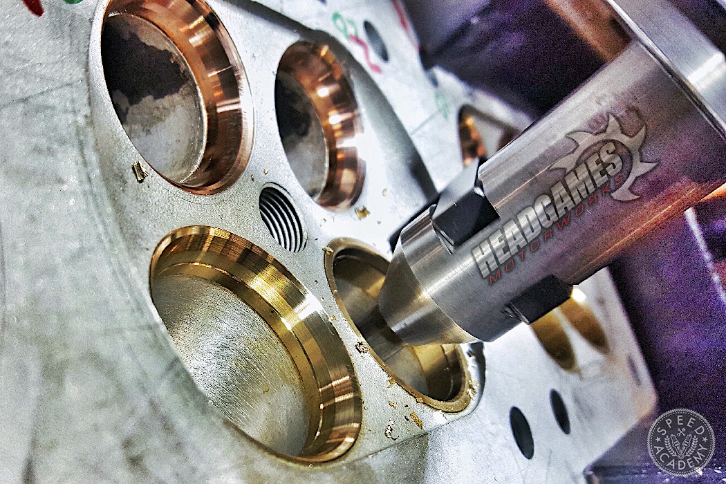
This one depends on the piece in the machine. If your making billet heads, the accuracy of the CNC is worth talking about, because you’re making something from scratch and making a batch of them ensures that they will all be the same. But when it comes to CNC machining a factory cast cylinder head, talking about the accuracy of the machine is a moot point. I say this because the factory head is cast, which means there will be some variation from head to head because of the imperfections that come from the casting process. That’s where the words “core shift” comes into play, because when we get cast heads back from the CNC shops there is not one that is exactly the same. In fact, in the head there is no ports that are the same. You can even see where the CNC did not touch the casting in one port but did in the others. That’s because the CNC machine does not know where the ports are, just where they are supposed to be. Meanwhile, a hand knows the center of that port every time. So, what does this mean? 

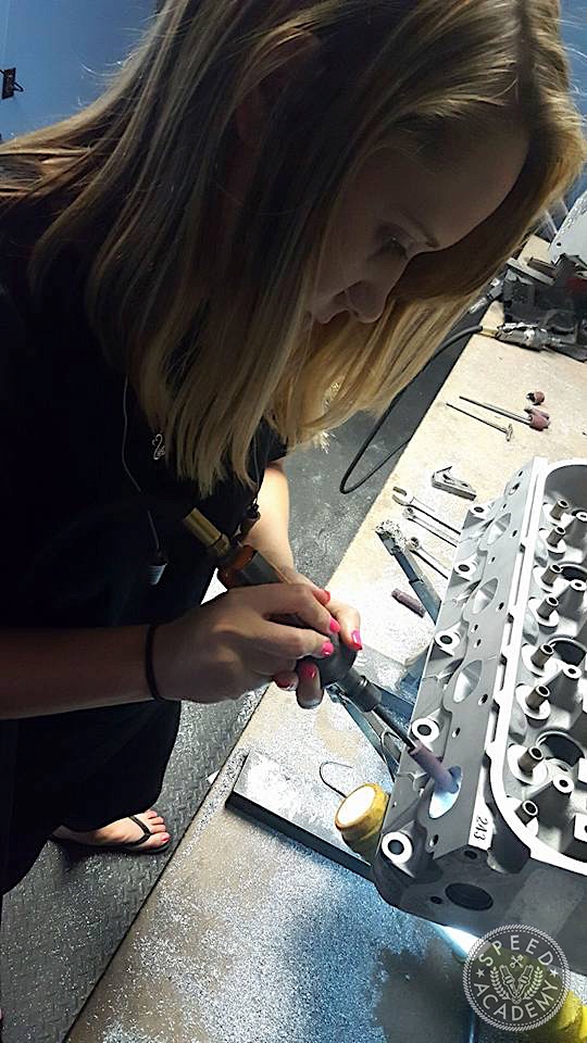
While a CNC is better than a hand at many things, when it comes to porting your factory cast cylinder head it is really just faster, meaning it’s faster than any human could grind and sand your head. So, instead of waiting weeks or months to get it back from the machine shop, someone with a CNC could rip through it in a few hours and have it on the floor ready for machine work. Talking about consistency machining an inconsistent part makes no sense except to market it as the best option. However, because there are cylinder head guys out there who do such a poor job hand porting, seemingly haven taken lessons from a blind person with a hammer and a chisel, they help perpetuate the myth that CNC porting is more accurate or “better”. 

Myth #2. Dimple Ports 

While we are on the subject, we should touch on dimple ports. The argument is that it works on golf balls because it creates a boundary layer of air and helps it move the ball faster and farther. In a port, we are looking to create a situation where fuel stays off the wall of the port. So the dimples would (in theory) help create this boundary layer of air that would keep the fuel off the wall and in suspense and atomized. 

First off, more than likely you have an engine with modern fuel injection if your reading this. Modern fuel injectors do an excellent job of atomizing the fuel, especially with todays engines where injector location is engineered very carefully for optimized delivery. So, the only true advantage I see in dimple ports is if you’re playing discus with the cylinder head and want to see how much farther you can throw it. If there was any real basis for dimple ports, you’d be seeing it in high-performance factory engines and professional level race engines and that’s simply not the case. 

Myth #3. Mirror Polishing

Charlie Kulp taught me how to grind. The man was working with Smokey Yunick back in the 1960s (look that name up on Google if you’re unfamiliar with Smokey, he’s a racing legend and innovator on a level few others could touch) and when they ran stuff in NASCAR they tried mirror polishing on the heads. It didn’t work then and it won’t work now. The reason being is that when you make the walls of the port too smooth, the air moves so fast and sticks to the walls of the port such that the fuel falls out of suspension, causing inconsistent fuel delivery to the combustion chamber. 


Myth #4. Bigger is Better 

It’s super easy to make a port as big as it can be. And we all know if it were easy, everyone would be doing it. But, that is kinda the problem. There are more places that believe in this theory than not. So, what you get is an industry full of heads that flow great from .500 lift on but are lazy on the car. Because velocity means more than flow! Air flow means something, and big ports and big valves don’t equal air speed. Simply put, the big stuff shines on the flow bench but runs like a dog with flees on the car.

Myth #5. Because It’s Ported, It’s Good For My Application 

Here is a gigantic misconception. With the advent of CNC you have a lot of performance shops and even CNC shops selling heads and selling them in one configuration. All of the them are ported to the max, with an oversize valve and flow insane numbers at max lift. But here’s the problem, your making 700 and want more power. You street drive the car a few hundred miles a month. You love beating on it. Put the big head on it and it losses all torque and has a dyno ramp that looks like a ski slope. That’s because the head is too big for your application. This is especially true with turbo cars. The max effort head will make the car lazy into boost. It will only make more peak power. That’s why asking for a flow sheet is so irrelevant. The dyno mimics the flow sheet in this case. It will make more jam, but where it makes the jam is what you should be concerned with.

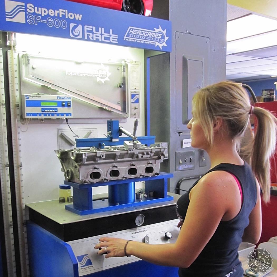
Myth #6. Flow Testing 

The biggest question we get daily,”What does it flow?” yet this is absolutely the most misunderstood part of cylinder head purchasing. And kind of where the bigger is better theory makes cylinder head sales. As stated above, you have a bunch of humans that don’t understand flow testing throwing everything at the head for the mighty CFM number at max lift and forget that it only hits this point once where they should be concentrating their efforts on everything that happens in between. The valve goes up and down through the lift ranges twice. The way the head behaves on the bench is indicative of how it will behave on the car most of the time. Why do I say most? There has been heads we have done that flow like a gangster at a rap party but run like a fat man chasing a banana. You can’t always believe the flow bench because there are so many different variables going on in the engine that the bench cannot capture or account for. Things like overlap, lift and duration of the camshaft can play a role. Asking “what does it flow” doesn’t necessarily help you make the right decision and often times it adds confusion for the novice buyer.

Myth #7. The Gasket Match 

This myth started on the domestic side of things. With the old heads, people would open the intake or exhaust port to a particular gasket. This was supposed to be the end-all performance enhancement. Truth is, there is zero thought by gasket manufactures on how big your port is supposed to be. The job of the gasket is to seal, not to enhance flow. When we look at this myth’s origins, people where trying to open up the cylinder head at its pinch point which would be the push rod restriction. Sport compact heads don’t have this restriction. And, the truth is most heads do not need a gasket match for the performance level they’re at. Here at HeadGames we do not usually open anything near the gasket til 1500-whp on 6-cylinder cars and 1200ish on a 4-cylinders. It’s better described as a port match and not a gasket match. Port match means that the port size most ideal for the port shape, NOT the gasket. 

Myth #8. Valve Jobs

Another question we get daily around here, “Do you do a radius valve job?” or “Do you do a 5 angle valve job?”. A valve job is not just a valve job. You can’t just throw any 5 angles or any angles at a head and expect results. Typically a valve job consists of 3 angles from the factory. Almost any cylinder head on every car since the 1960s has a 45-degree “seat” angle (with the exception of muscle Pontiac and Oldsmobile that had a 30-degree seat angle). We say seat angle, because this is the angle which the valve sits on when it is closed. Then there is a top and a bottom cut. When we add angles, they are added to the bottom of the 45. An example of a 3 angle would be 35-45-60 angles. When we increase the number of angles, we would say 35-45-60-70-90 for a 5 angle. Now, that we have the number of angles, the only way to really know what angles actually like to be on the head, we have to use the flow bench, dyno and on-track testing. We do extensive, labor intensive testing on every head for valve jobs. Not any valve job work just because it has a number of angles. They have to be the right angles for that particular cylinder head.

Also, radius valve jobs are a popular question. Do they work? Sometimes. Do they work on everything? NO. The radius looks great, and feel it up with a finger and you might think this is the most awesome invention since sliced bread. But on the flow bench and on the car it can be a heart breaker. There is more instances than not where a full radius valve job will hurt more than help. This is especially true on an intake seat.  Air doesn’t like to turn. It likes straight paths. And it loves angles. But not too many, because too many angles on a small seat can make it a radius.


Myth #9. Big Valves 

Tied to the subject of valve jobs, larger valves are certainly a big part of why people use them. Here is the deal. In the multi valve community, there are many places that do an oversized valve simply because they do not have valve job technology. But if you don’t have valve job technology, then you probably don’t know where to put the throat diameter. The area under the valve seat has more potential for flow than almost anywhere else in the head! It also has the biggest potential to hurt flow by being too small or too big!

Myth #10. Port Shape

Port shape is the second biggest advantage when it comes to a ported head. When we port heads by hand, a lot of people ask, how do you know when to stop? Well, the answer is in the port shape. Once the shape is mapped out then you just make everyone the same. But, this is where the flow bench can be your friend or your heart breaker, depending on what transpires. It’s almost impossible to decipher this unless you have owned a flow bench or see enough ports to know what shapes change flow characteristics on particular cylinder heads.

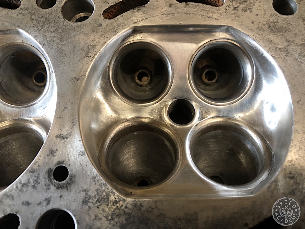
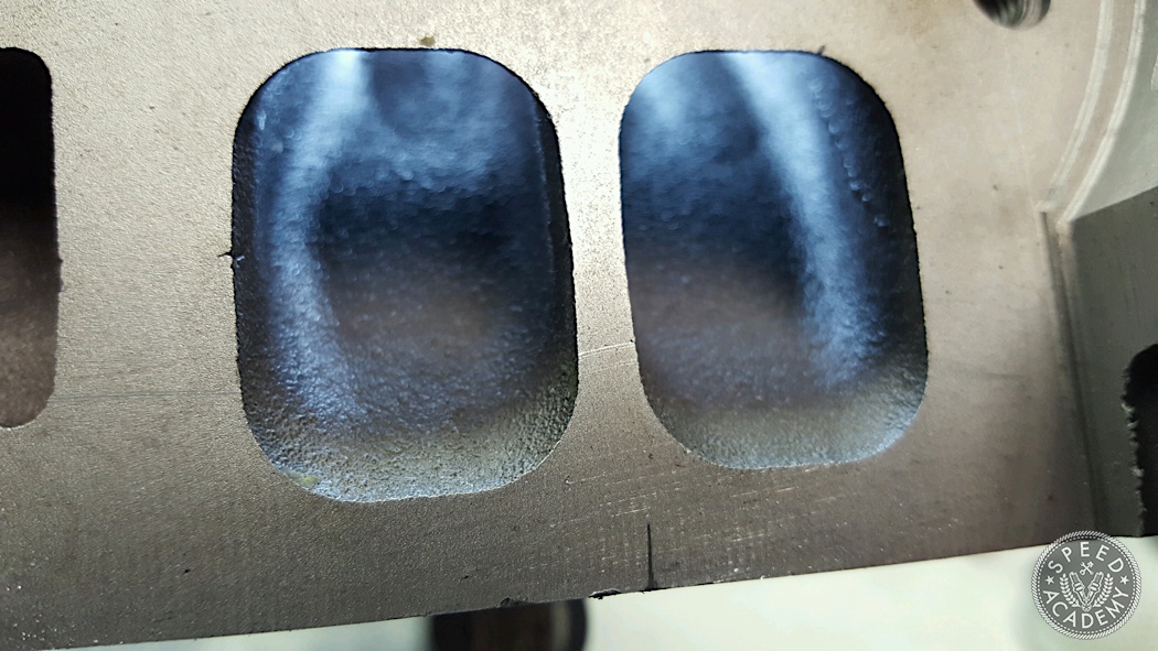
Best way to show this is by an example we had in our development in the 4-cylinder Mustang Ecoboost head.

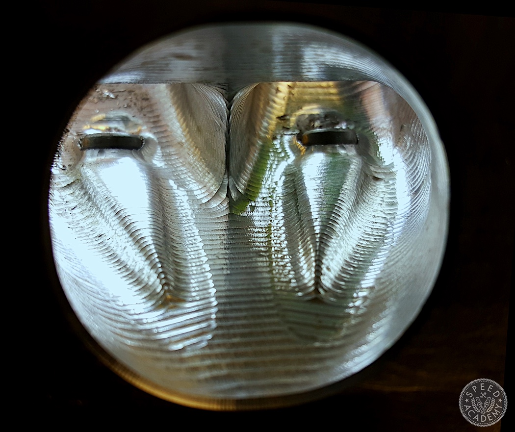
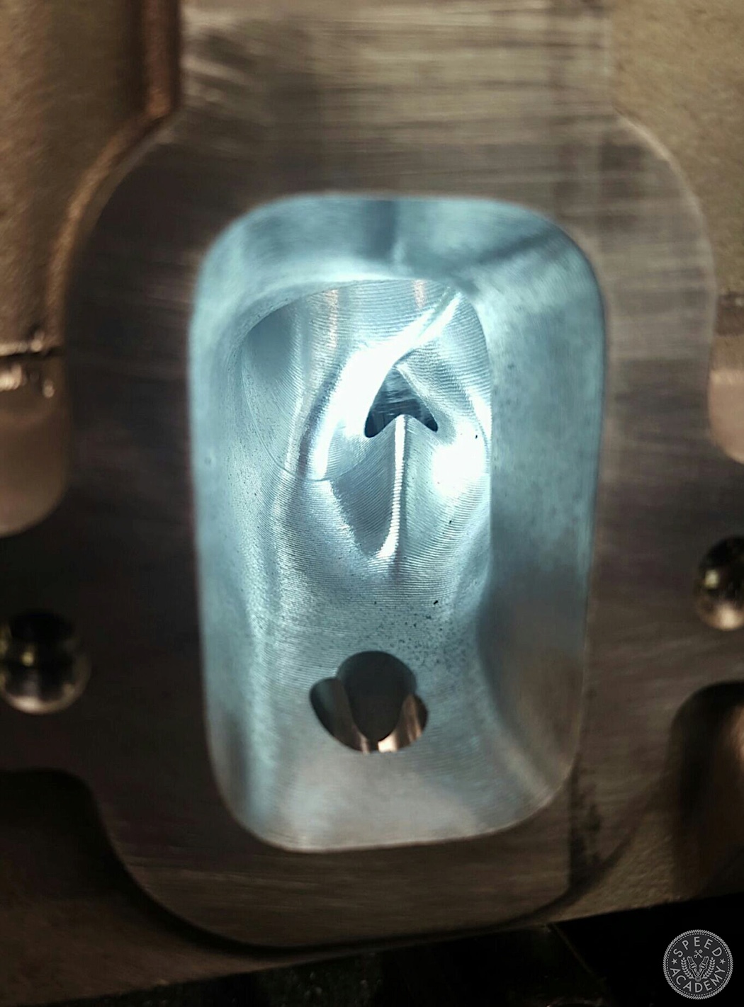
When we first looked at this head, it was easy to see how Ford completely separates the two intake ports. No sport compact head does this so far out into the port. The port is very long and small. Seeing other heads on the market, most are knocked back the center of the 2 ports and made it appear to be a larger runner. It looks awesome!

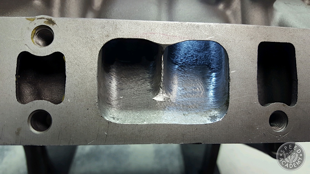
So, we did one port to see what it does on the bench and only did that section of the port to see how it behaved. WELL…it didn’t behave well at all. In fact, it lost 40 cfm almost everywhere. Thinking maybe it was the way we shaped it vs the competition, we mimicked their port entrance for the second testing. Same results. It was obvious no one had actually tested this on the flow bench until now. 

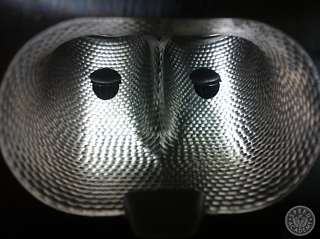
So if we were losing so much airflow, where was it going? Well, when you don’t know you ask someone smarter. We hit up our friends at McLaren, Dan Archer and Tim “the airflow doctor” Connelly. We went through the port and by using velocity probes learned that the air flow had actually moved to a corner of one port side because of the divider! It looked cool, but didn’t work. 

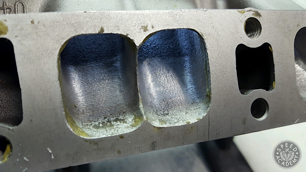
We went back to the drawing board and kept the divider. Ported and just changed the shape of the intake port. 90 cfm gain! And this head went on to set the national ET record.


Posted on Leave a comment

Stroker Science: Piston Speed, Rod Angle, and Increased Displacement Explained.


August 20, 2018 / by Mike Magda

An intense look at crankshaft stroke and its affect on mean piston speed, inertia, and controlling the massive, destructive forces at work inside an engine.

Engine builders have long calculated the mean piston speed of their engines to help identify a possible power loss and risky RPM limits. This math exercise has been especially important when increasing total displacement with a stroker crankshaft, because the mean piston speed will increase when compared to the standard stroke running at the same RPM.

But what if there was another engine dynamic that could give builders a better insight into the durability of the reciprocating assembly?

The video above shows two engines, one with a short stroke crankshaft, and the other with a considerably longer stroke. Note that both pistons reach top dead center and bottom dead center at the same time, but the piston in the longer stroke engine (left) has to move significantly faster. 

“Rather than focus on mean piston speed, look at the effect of inertia force on the piston,” suggests Dave Fussner, head of research and development at K1 Technologies.

Let’s first review the definition of mean piston speed, also called the average piston speed. It’s the effective distance a piston travels in a given unit of time, and it’s usually expressed in feet per minute (fpm) for comparison purposes. The standard mathematical equation is rather basic: 

Mean Piston Speed (fpm)=(Stroke x 2 x RPM)/12

There’s a simpler formula, but more on the math later. A piston’s velocity constantly changes as it moves from top dead center (TDC) to bottom dead center (BDC) and back to TDC during one revolution of the crankshaft. At TDC and BDC, the speed is 0 fpm, and at some point during both the downstroke and upstroke it will accelerate to a maximum velocity before decelerating and returning to 0 fpm.

As the piston races from bottom dead center to top dead center, for a brief moment, it comes to a complete stop. This places tremendous stress on the wrist pins. Shown, these Trend pins are offered in various wall thicknesses to deal with the required load.

There are formulas to calculate the piston speed at every degree of crankshaft rotation, but that’s usually much more information than needed by most engine builders. Traditionally they look at the average or mean piston speed during the crank rotation, and they possibly will calculate the maximum piston speed.

The mean piston speed takes the total distance the piston travels during one complete crankshaft revolution and multiplies that by the engine RPM. Piston speed obviously increases as the RPM increase, and piston speed also increases as the stroke increases. Let’s look at a quick example.

To view all of K1 Technologies’ Crankshaft offerings, click HERE

A big-block Chevy with a 4.000-inch-stroke crankshaft running at 6,500 rpm has mean piston speed of 4,333 fpm. Let’s review the formula again used to calculate this result. Multiply the stroke times 2 and then multiply that figure by the RPM. That will give you the total number inches the piston traveled in one minute. In this case, the formula is 4 (stroke) x 2 x 6,500 (RPM), which equals 52,000 inches. To read this in feet per minute, divide by 12. Here’s the complete formula:

(4 x 2 x 6,500)/12=4,333 fpm

You can simplify the formula with a little math trick. Divide the numerator and denominator in this equation by 2, and you’ll get the same answer. In other words, multiply the stroke by the RPM, then divide by 6.

(4 x 6,500)/6=4,333 fpm

With this simpler formula, we’ll calculate the mean piston speed with the stroke increased to 4.500 inch.

(4.5 x 6,500)/6=4,875 fpm

As you can see, the mean piston speed increased nearly 13 percent even though the RPM didn’t change.

Reducing piston weight plays a huge role in creating a rotating assembly that can sustain high rpm. The seemingly insignificant gram weight of a piston is magnified exponentially with rpm.

Again, this is the average speed of the piston over the entire stroke. To calculate the maximum speed a piston reaches during the stroke requires a bit more calculus as well as the connecting rod length and the rod angularity respective to crankshaft position. There are online calculators that will compute the exact piston speed at any given crankshaft rotation, but here’s a basic formula that engine builders have often used that doesn’t require rod length:

Maximum Piston Speed (fpm)=((Stroke x π)/12)x RPM

Let’s calculate the maximum piston speed for our stroker BBC:

((4.5 x 3.1416)/12)x 6,500=7,658 fpm

By converting feet per minute to miles per hour (1 fpm = 0.011364 mph), this piston goes from 0 to 87 mph in about two inches, then and back to zero within the remaining space of a 4.5-inch deep cylinder. Now consider that a BBC piston weighs about 1.3 pounds, and you can get an idea of the tremendous forces placed on the crankshaft, connecting rod and wrist pin—which is why Fussner suggests looking at the inertia force.

“Inertia is the property of matter that causes it to resist any change in its motion,” explains Fussner. “This principle of physics is especially important in the design of pistons for high-performance applications.”

When the connecting rod is lengthened, it provides a softer transition as the piston changes direction. The longer connecting rod also reduces the compression height of the piston and can help pull weight out of the rotating assembly.

The force of inertia is a function of mass times acceleration, and the magnitude of these forces increases as the square of the engine speed. In other words, if you double the engine speed from 3,000 to 6,000 rpm, the forces acting on the piston don’t double—they quadruple.

“Once started on its way up the cylinder, the piston with its related components attempt to keep going,” reminds Fussner. “Its motion is arrested and immediately reversed only by the action of the connecting rod and the momentum of the crankshaft.”

Due to rod angularity—which is affected by connecting rod length and engine stroke—the piston doesn’t reach its maximum upward or downward velocity until about 76 degrees before and after TDC with the exact positions depending on the rod-length-to-stroke ratio,” says Fussner. 

Stroker cranks such as this forged LS7 piece from K1 Technologies, are a great way to add displacement. However, when the stroke is lengthened the piston must accelerate faster each revolution to cover the larger swept area of the cylinder wall. Looking for an LS Stroker crankshaft? Click HERE.

“This means the piston has about 152 degrees of crank rotation to get from maximum speed down to zero and back to maximum speed during the upper half of the stroke. And then about 208 degrees to go through the same sequence during the lower half of the stroke. The upward inertia force is therefore greater than the downward inertia force.”

If you don’t consider the connecting rod, there’s a formula for calculating the primary inertia force:

0.0000142 x Piston Weight (lb) x RPM2 x Stroke (in) = Inertia Force

The piston weight includes the rings, pin and retainers. Let’s look at a simple example of a single-cylinder engine with a 3.000-inch stroke (same as a 283ci and 302ci Chevy small-block) and a 1.000-pound (453.5 grams) piston assembly running at 6,000 rpm:

0.0000142 x 1 x 6,000 x 6,000 x 3 = 1,534 lbs

With some additional math using the rod length and stroke, a correction factor can be obtained to improve the accuracy of the inertia force results.

Crank Radius÷Rod Lenth

“Because of the effect of the connecting rod, the force required to stop and restart the piston is at maximum at TDC,” says Fussner. “The effect of the connecting rod is to increase the primary force at TDC and decrease the primary force at BDC by this R/L factor.”

For this example, the radius is half the crankshaft stroke (1.5 inch) divided by a rod length of 6.000 inches for a factor of .25 or 383 pounds (1,534 x 0.25 = 383). This factor is added to the original inertia force for the upward stroke and subtracted on the downward movement.

Both the crank on the left and right are at the same point in their respective rotations. However, the piston on the left will have to travel much faster to reach top dead center at the same time as the piston on the right.

“So, the actual upward force at TDC becomes 1,917 pounds and the actual downward force at BDC becomes 1,151 pounds,” says Fussner. “These forces vary in direct proportion to the weight of the piston assembly and the stroke to rod length and they also vary in proportion to the square of the engine speed. Therefore, these figures can be taken as basic ones for easily estimating the forces generated in any other size engine.”

By the way, the mean piston speed for this 1-cylinder engine at 6,000 rpm is 3,000 fpm, and the maximum piston speed (using our previous formula) is 4,712 fpm.

What happens when you increase the stroke from 3.000 inch to 3.250-inch? First, the mean piston speed increases to 3,250 fpm, and the maximum piston speed jumps to 5,105 fpm. Then the primary force increases from 1,534 pounds to 1,661 pounds. There’s also a change when adding in a new R/L factor of .27 (1.625 ÷ 6.000). The actual upward force at TDC becomes 2,109 pounds and the actual downward force at BDC becomes 1,213 pounds.

“If we increase the engine speed with the 3.250-inch stroke to 7,000 rpm, leaving all other details equal, the primary force increases to 2,261 pounds,” says Fussner. “Then apply the R/L factor of .27, and the actual downward force becomes 1,651 pounds. The actual upward force at TDC becomes 2,871 pounds. That’s nearly a ton and a half!”

Now consider the effects of a lighter piston. Keeping the 3.20-inch stroke and 7,000 rpm but going to a piston that weighs 340 grams (.750-pound), the maximum force is reduced from 2,871 pounds to 2,154 pounds, or 717 pounds of less force. This same lighter piston configuration would have a force of 1,238 pounds required to stop and restart the piston at BDC, a reduction of 413 pounds.

“So, with every complete revolution, the engine would see 1,130 pounds less inertia force with the lighter piston assembly,” says Fussner. “This reduction of inertia force would, of course, be applied to each cylinder in a multi-cylinder engine. An engine running 7,000 rpm will stop and start each piston 14,000 times a minute.”

As the piston reaches top dead center on the exhaust stroke, their is no cushion of compression to help slow it down. Instead, the connecting rod takes the full brunt of the force which pulls on its beam and tries to separate its cap. Quality connecting rods are paramount to a high-horsepower, high-rpm engine. Looking for forged connecting rods? Click HERE!

Mean and maximum piston speeds are still valuable calculations for any engine builder making a change to a proven formula. Exceeding 5,000 fpm in mean piston speed should get your attention and prompt rethinking on parts selection. Excessive piston speed can lead to inconsistent lubrication of the cylinder wall, and in some situations the piston will actually accelerate faster than the flame front during combustion. While the former can cause parts failure, the latter is lost horsepower.

And the pistons should also be the lightest possible without sacrificing the required strength and durability. The inertia forces will stretch connecting rods and resist crankshaft acceleration—again potentially leading to parts failure and choking horsepower.

“We know a common measure used for many years to suggest the structural integrity danger zone of a piston in a running engine is mean piston speed,” sums up Fussner. “As the skydive instructor told his student, it’s not the speed of the fall that hurts, it’s the sudden stop. And so it is with pistons. So rather than focus only on the mean piston speed, let’s decide to also consider the effect of inertia force on the piston, and what we can do to reduce that force. And if that is not possible, make sure the components are strong enough to endure the task we have set forth.”

“While increasing the rod length will soften the inertia loading by changing the afore mentioned R/L ratio, it will not reduce the mean piston speed because as long as the stroke is not changed,” continues Fussner. “The piston still must travel the same distance in one revolution of the crankshaft, regardless of the rod length. Speed is distance traveled per unit time.”

A final note on piston speed—, 2,500 fpm was considered the upper limit for piston speed not too long ago. It is important to consider that mean piston speed is also used as guide for considering other engine components, such as connecting rods and crankshafts. In the early days of hot rodding, most engines had cast iron cranks and rods and cast aluminum pistons, which are not nearly as strong as engine parts today. 

“So, adding strength to these parts has allowed the safe mean piston speed to more than double to 5,000 fpm or more,” says Fussner. “Another factor is the usage. Will the engine be operated for extended periods at high piston speed, or for a quick pass down the drag strip? Reducing the exposure time at high piston speeds increases reliability. Strong, light components will be able to endure higher pistons speeds than heavy lower strength components.”

WhatsApp WhatsApp us