Posted on Leave a comment

Misunderstood Causes of Detonation in High Performance Applications

In the engine tuning world, detonation is defined as one of the following: combustion that causes engine damage; combustion that causes banging or pinging noises; or combustion that causes power loss, bucking, or kicking. Detonation is not controlled and often unwanted. It occurs when fuel in the cylinder auto-ignites outside the intended flame front of the spark ignition.

Detonation does not always cause damage. At lower engine loadings during part throttle or low RPM, detonation may be warranted. For example, during the late ’70s and ’80s, pinging during normal operation was common with carbureted engines. Certain intake manifold design compromises combined with smog equipment caused lean fuel mixtures that burned outside of the controlled flame front from the spark plug.

Minor detonation sometimes occurs that is not heard through mufflers at low load or even with loud open exhaust. Major detonation causes a more severe noise during engine loading where the throttle is open and the engine is twisting hard against a heavy load.

Detonation and Preignition

Preignition is auto-ignition of the air/fuel mixture before the spark plug fires. The auto-ignition occurs at a location in the cylinder outside of the controlled flame front from spark ignition.

Similarly, detonation is auto-ignition of fuel, usually after the spark plug fires. Like preignition, detonation occurs outside of a controlled flame front from the spark plug. The term detonation is often used by racers as both preignition (before the spark), as well as uncontrolled burning after the spark. The same convention is used in this article.

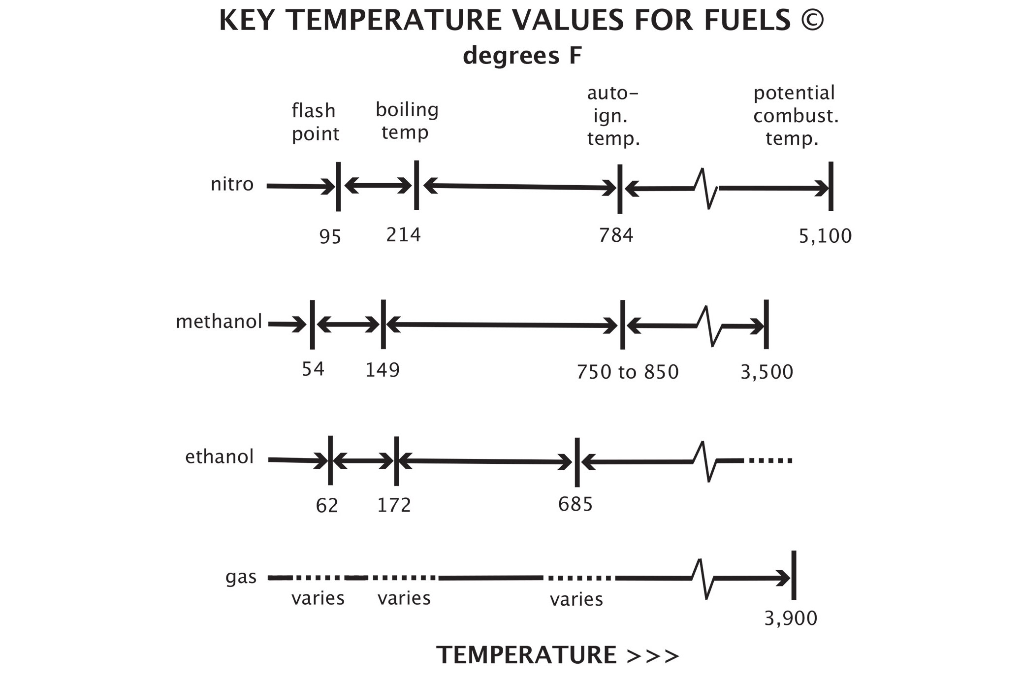
This illustration is from 5000 Horsepower on Methanol (Bob Szabo, Szabo Publishing, 2006) showing auto-ignition temperatures for various racing fuels.

Both preignition and detonation are from auto-ignition of fuel. They share characteristics — like a very high burn speed — which are comparable to explosive flame speeds. These include firearms muzzle velocities or explosives combustion velocities — typically well over 1,000 feet per second. The high velocity causes noise due to pressure fronts that collide within the cylinder.

Detonation and RPM

Detonation can be masked at higher RPM by high frequency noise, like that of an exhaust valve opening. It can be such a brief occurrence that it doesn’t cause damage before the exhaust valve opens, relieving the cylinder pressure and ending the detonation.

At lower engine speeds the time between detonation and opening of the exhaust valve is a longer interval, so detonation is more noticeable. As the RPM increases, it may sound like the detonation goes away because of shorter intervals between detonation and opening of the exhaust valve.

Racing engines in the ’30s and ’40s ran on lower octane gasoline, as higher octane gasoline was not yet developed. The lower octane fuels were susceptible to detonation as racers raised engine compression ratio for more power. Detonation was especially detectable at low engine speeds. To combat the low-speed detonation, those early racing engines were revved continuously at higher engine speeds to inhibit the effects of detonation.

If the engine was lugged by mistake, detonation could cause poor performance and possible engine damage. As a result, drivers coming into the pits for service would free-rev their engines continuously. Slipping the clutch to launch from the pits became an art form for many successful racing drivers. When starting in the pits, there was a great risk of engine stalling from a combination of inadequate clutch slipping, low engine torque at low-RPM, and detonation at low-RPM.

The best performance for modern day gasoline-fueled engines is achieved with a racing gasoline blend with an octane rating just high enough to avoid detonation. A gasoline blend with a higher octane rating does not usually increase performance by itself. Instead, the slower burn rate of high octane gasoline will often actually reduce an engine’s performance without other changes made to take advantage of the higher octane.

Gasoline’s octane need is characteristic of a specific RPM operating range. If that range is changed, a racing gasoline with a different octane may be needed. For example, if the engine spends more time under load at a lower engine speed, the engine may encounter detonation, whereas it would not detonate at the same load higher in the RPM range. A racing gasoline with a higher octane may be needed to combat the potential for detonation operating in the lower RPM range.

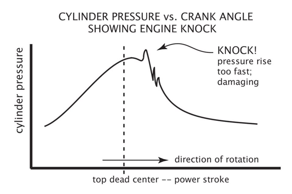
Illustrations from 5000 Horsepower on Methanol showing cylinder pressure vs. crankshaft angle for good combustion on left and detonation on right.

Dissociation From Combustion

Fuels dissociate, or break down, into different intermediate chemicals during compression, heating, and combustion. These intermediate chemicals can alter the auto-ignition temperature of the mixture from that of the original fuel alone. Many times, the wrong tune-up call is made because of detonation, assuming data based on just the properties of the primary fuel, when auto-ignition temperature changes from dissociation should have been taken into account.

In blown alcohol drag racing, competitors with higher static compression usually have to run a richer mixture than those with lower static compression to inhibit detonation. However, there is a point at which the need for additional enrichment tapers off. One competitor reported that beyond a certain point in compression increases, further enrichment was not needed, while the engine made more power with more compression. He continued to raise compression further and achieved national record-running performance. At a certain point, the extra-high compression was actually preventing the formation of detonation-sensitive dissociates.

Dissociate Causes of Detonation

With different racing fuels, some of the previously described dissociate formations can be more prone to detonation than others. The tune-up can affect the compression and heating which will affect what dissociates are formed, even with the same fuel. These dissociates then affect the detonation sensitivity. Additionally, air density changes affect the tune-up which, once again, affects dissociation in a vicious cycle.

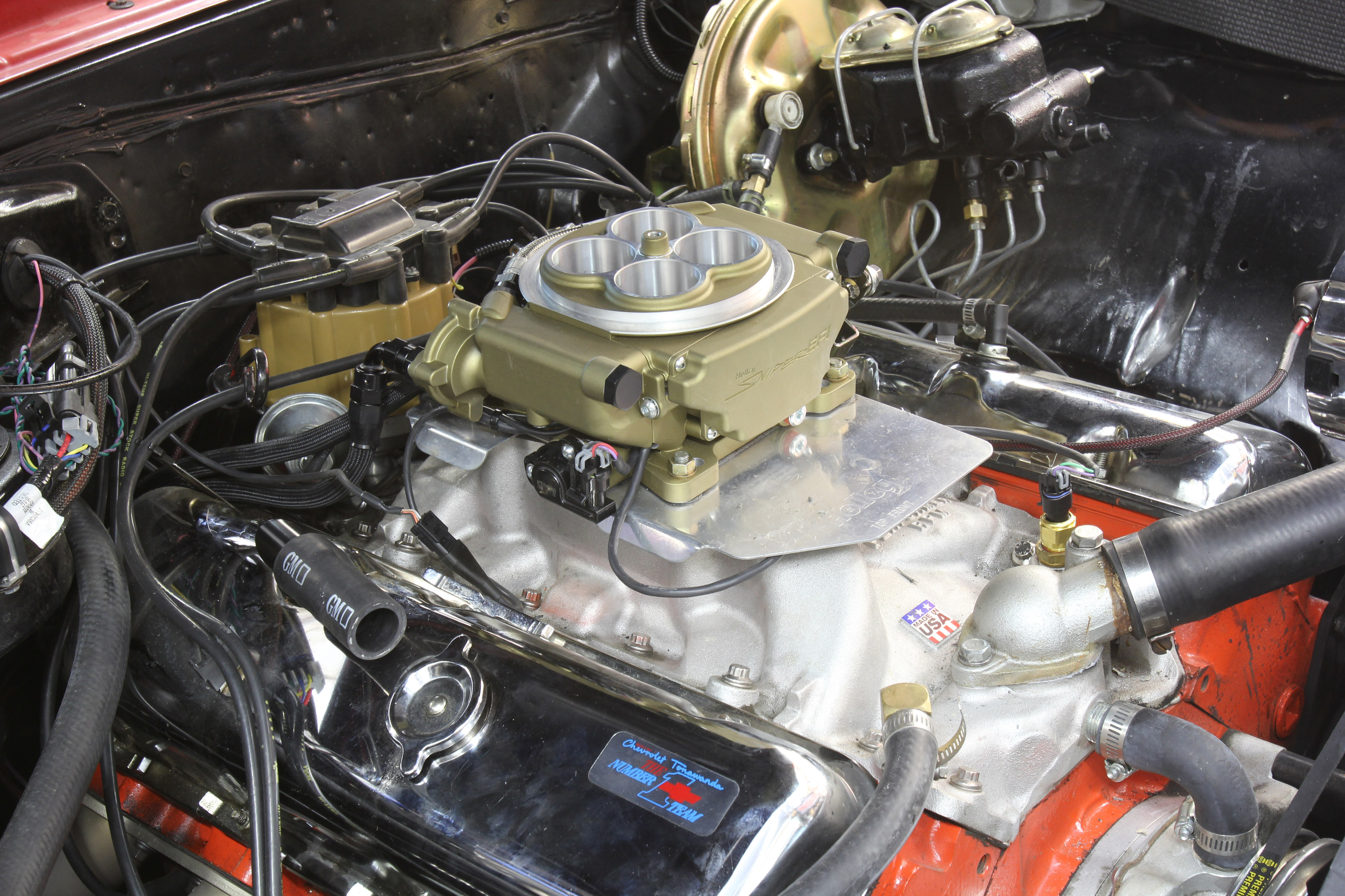
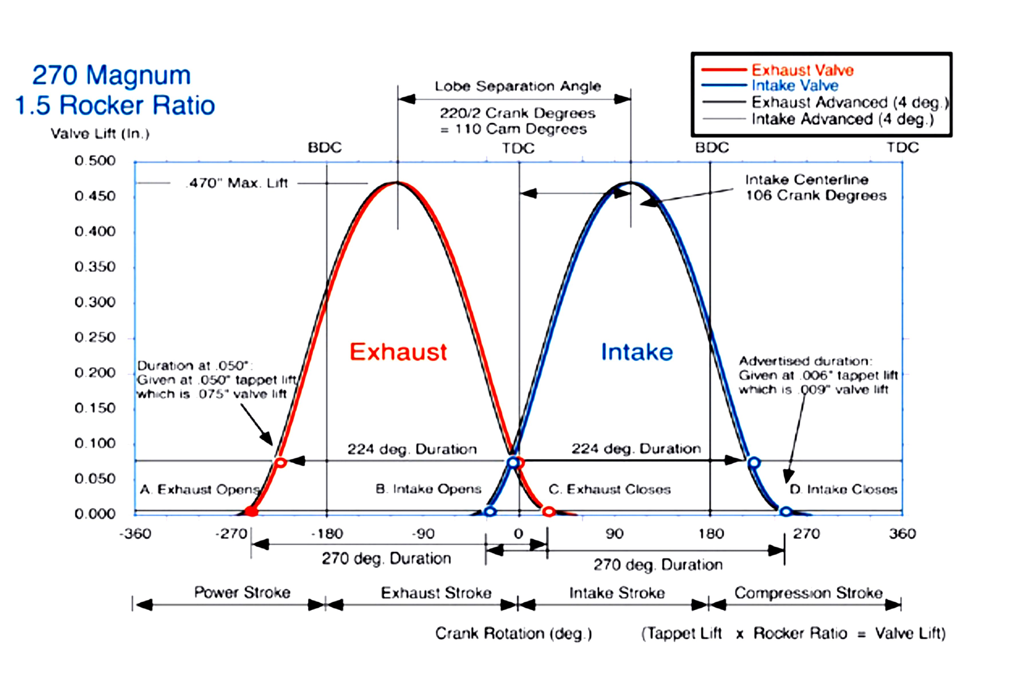
For example, changing the closing point of the intake valve in a spark ignition racing engine will change the effective dynamic compression. Changing the compression changes the adiabatic heating and pressure from compression. Sensitivity towards or away from detonation can be triggered by something as simple as a camshaft change or even just retarding or advancing camshaft timing.

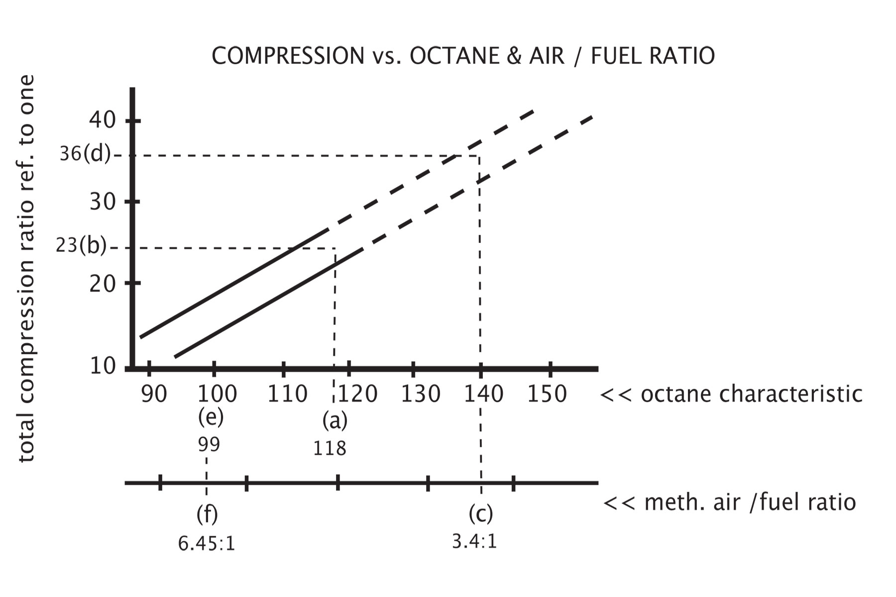
This illustration from 5000 HP on Methanol shows the relationship between compression ratio and air/fuel ratio for detonation-free operation for methanol racing fuel. Data points, (a) through (e) were determined from various racing engines. This curve also depends on a proper level of enrichment to retard auto-ignition that is further described in the reference.

Pressure Changes Causing Ignition

Pressure changes the auto-ignition temperature of both the fuel and fuel dissociates, which can initiate detonation. An auto-ignition temperature of a fuel dissociate may be lower than the auto-ignition temperature of the fuel before it breaks down, which can be confusing, when looking at the data for the fuel alone.

During compression, say a mixture of air and dissociated fuel is below the auto-ignition temperature. The pressure wave generated in the cylinder can inhibit this mixture from igniting. However, as the pressure wave goes through the cylinder, it can trigger a change in the auto-ignition temperature of the mixture. Auto-ignition can follow as the pressure wave passes due to the accompanying drop in auto-ignition temperature, strictly from the chemical sensitivity change. Additionally, changes in the cylinder head from piston squish or unshrouding an intake valve can change the pressure wave formation and affect the combination’s overall detonation sensitivity.

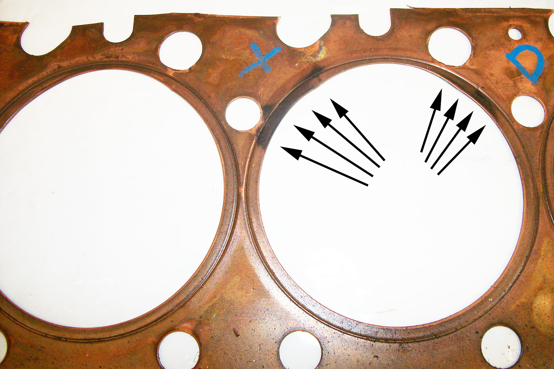
The O-ring indent on this used copper head gasket around the cylinder opening shows the start of burn-through in the tight O-ring mating surface just before detonation from a nitromethane methanol fuel mixture. Enrichment to this cylinder & new head gasket avoided a reoccurrence. Photo Credit: Blown Nitro Racing on a Budget (Bob Szabo, Szabo Publishing 2013).

Dissociation With Different Fuels

Gasoline

According to writings by the late Harry Ricardo (The High-Speed Internal-Combustion Engine, 3rd Edition, Blackie & Son Limited, 1950), who was a combustion engineering expert, unstable peroxides are formed as intermediate dissociates during gasoline combustion, which happen to be very prone to detonation. Tetra-ethyl lead is a reactive metallic addition that suppresses detonation from these unstable peroxides. In addition, various gasoline fuel constituents used in common blends have different dissociation properties to help combat the formations of the unstable peroxides. Examples of these constituents used are pentane, hexane, and toluene.

Fuel blending in modern gasolines is done to achieve detonation resistance, among other characteristics. In many racing gasoline brands, several are also blended with tetra-ethyl lead for the same purpose. Other characteristics such as chemical stability, ease of vaporization so that the engine can be started, and manufacturing cost, often limit blend additives and ratios. Those constraints can compromise the detonation resistance capability of some gasoline brands over others under given circumstances. The ideal result is a best-fit mixture or blend to fulfill the particular racing requirement, and why so many different racing gasoline variations exist.

Gasoline blends sold at the pump most often have seasonal changes in blend ratios and fuel content. Winter gasoline is blended for ease of starting, while summer gasoline blends are designed for vapor-lock avoidance. Different seasonal blends will change the dissociation and detonation characteristics, and needs to be accounted for in a performance application. Pump gasoline purchased in one season may encounter detonation issues if it is run in another season, due to the variance in blend.

Ethanol Gasoline Blends (E85)

E85 is predominantly (85-percent) ethanol with a small amount (15-percent) of gasoline added. The ethanol content’s high effective octane rating suppresses detonation in high-compression-ratio racing engine if the air/fuel ratio is rich. That would be a lambda of less than one in the EFI computer world. A rich alcohol fuel mixture also cools the cylinder away from auto-ignition temperatures. These rich air/fuel ratios can be run with a predominant alcohol fuel since alcohol does not foul out a spark plug like other fuels can. However, excessive richness reduces power output, so tuning the air/fuel ratio is vital. On the other end of the specturm, excessively rich mixtures can cool the intake too much, suppressing vaporization and inducing detonation from a vapor lean condition. This is the result of excess fuel condensation from cooling.

Methanol

Methanol as well as ethanol will dissociate into hydrogen and carbon monoxide during compression heating. Methanol and ethanol will also partially dissociate into hydrogen and carbon monoxide during boost in an engine with large enough pressures from forced induction, prior to, and in addition to piston compression. However, compression pressure retards the amount of dissociation that occurs. Therefore heat causes dissociation to go in one direction, and pressure from compression (or boost) causes dissociation to go in another. Combustion is then a combination of hydrogen, carbon monoxide, and any remaining methanol vapor that has not dissociated.

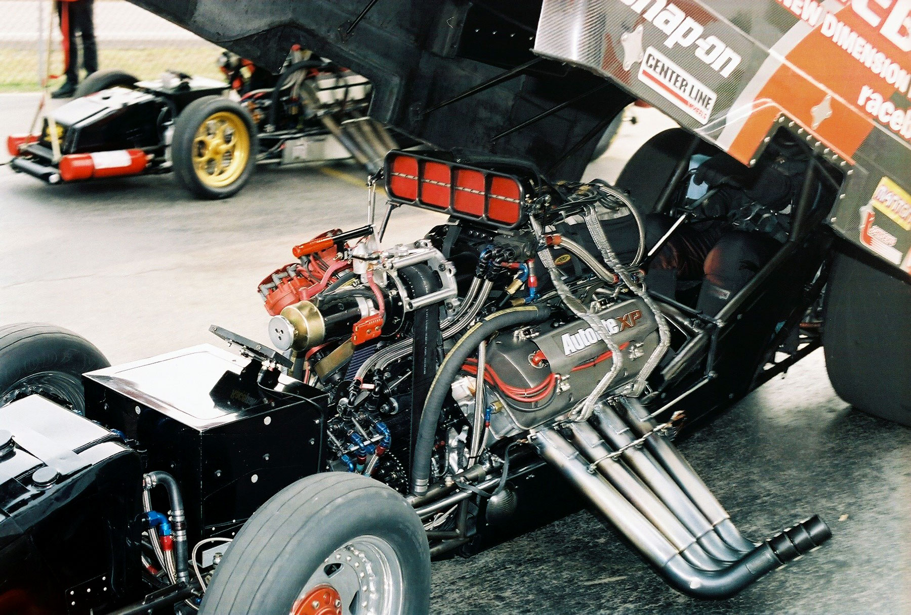
A Funnycar Dragster launches for 300 mph drag race runs at Norwalk Raceway Park, Ohio during an IHRA national event with detonation fighting tune-ups from high-percentage nitromethane methanol fuel mixtures

Differences in compression, engine temperature, camshaft timing, and boost in forced induction engines all affect the amount of dissociation that occurs. The amount of dissociation then affects the combustion characteristics of the charge. For example: hydrogen has very low ignition temperature and is more prone to backfiring into the intake, as it doesn’t necessarily need a traditional ignition source. That is often mistaken as detonation when, in fact, it is excess hydrogen dissociation that is reacting.

A tune-up or air density change can change the hydrogen dissociation and make or avoid engine backfiring. When backfiring from hydrogen dissociation occurs, subsequent engine disassembly often does not reveal any engine damage. The variation in auto-ignition temperatures of methanol is due to different amounts of dissociation from the tune-up and air density changes.

Methanol has oxygen in the fuel while traditional gasoline does not. As such, methanol can detonate with less air in the mix than gasoline. An air/fuel weight-ratio of 8-to-1 would be overly rich for gasoline and not detonate but could detonate with methanol fuel. That threshold changes with oxygen variations in the air from air density changes.

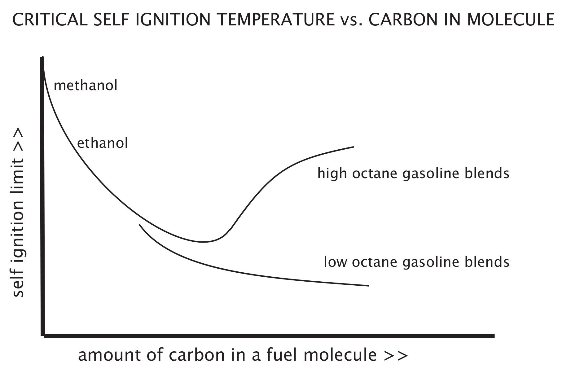
Data as reported in 5000 HP on Methanol from Germane and Lovell indicate a relationship between the amount of carbon in a fuel molecule and auto-ignition temperature. (Germane, Geoff J., Brigham Young University, A Technical Review of Automotive Racing Fuels, SAE 1985, Publication #852129)(Lovell, W. G., Knocking Characteristics of Hydrocarbons, Industrial and Engineering Chemistry, Vol. 40, pp. 2388-2438, December, 1948)

Nitromethane

Nitromethane dissociates in different phases. For a brief moment, some of these phases are sequential, and some are even simultaneous during the ignition and combustion process. However, many phases of nitromethane dissociation occur simply from compression heating and combustion.

The first phase is endothermic. It absorbs heat and acts like it is hard to ignite. This is why a magneto ignition with a long spark dwell time is more effective with nitromethane fuel mixtures to get past the first dissociation phase of combustion. The second and remaining dissociation phases of nitromethane combustion can be exothermic, that is, burning and giving off heat (Chem-Supply Material Safety Data Sheet, nitromethane, 1CHOP, December, 2000).

Multiple dissociation phases occur during combustion with different intermediate compounds and with different auto-ignition (detonation) characteristics. Different mixtures of nitromethane and methanol add further complexity to detonation sensitivity changes since methanol has its own set of dissociates and behaviors. As a result, the tuning directions can be troublesome and inconsistent from run to run.

Some nitro tune-ups may be more prone to detonation when leaning the mixture (higher air/fuel ratio). Some nitro tune-ups may be more prone to detonation with enrichment of the mixture (lower air/fuel ratio). The best tune-up routine is to make as few changes as possible to engine compression, boost, fuel mixture, fuel temperature, and others to dial-in engine power for the performance envelope. Making multiple changes from run to run makes it almost impossible to get control over the tune-up, because of that wandering auto-ignition temperature characteristic. Major engine failures can occur as a result.

Recent photo of 300 mph Nitro Funnycar drag racecars staged for startup at an IHRA National Event drag race with detonation-sensitive tune-ups from 90-percent nitromethane mixtures.

Air/Fuel Ratio Changes

Changes in air/fuel ratio will also change the auto-ignition sensitivity characteristics. This change is complex depending on the amount of enrichment. Enrichment up to a point tends to decrease the auto-ignition sensitivity. Enrichment in methanol or ethanol can cool the cylinder temperature to where the engine will not detonate. Excess enrichment beyond a certain air/fuel ratio with those fuels can increase the auto-ignition sensitivity however. By causing excessive cooling and fuel condensation out of the inlet air charge, a vapor-lean condition is created and auto-ignition can occur. It can also slow down the flame speed, extending the combustion event into the exhaust stroke. That can lead to a backfire in the intake when the intake valve opens.

In the other direction, less enrichment beyond a certain optimum air/fuel ratio tends to increase the auto-ignition sensitivity. With methanol or ethanol, less enrichment will not cool the cylinder temperature enough, raising temperature enough to where the engine may then detonate, especially if high compression ratios are used.

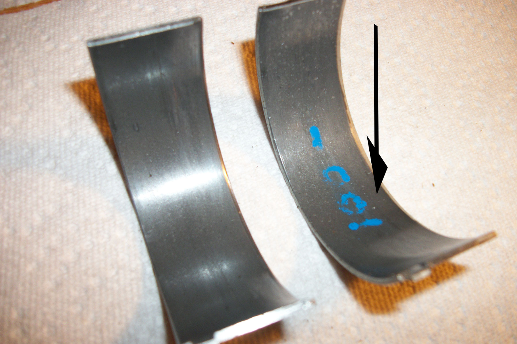
A unique race tuning trick is to run the engine up to the limit of detonation then disassemble the engine and measure the thickness of upper rod bearings. The bearing on the left measured no thinning after a run. The bearing on right is from the same cylinder after another run with some detonation-induced thinning. Some engine builder/tuners use bearing thinning as an indicator of an amount of detonation. Some early nitro drag racing engine builder/tuners mastered this method of a certain amount of rod bearing thinning as an indicator of a good tune-up.

Excessive reduction of enrichment may reduce power since there is less fuel to burn. Continued reduction of enrichment beyond a certain point may not detonate since the extreme lean condition results in a shortage of fuel to burn, and flame speed slows down. Somewhere in that lean direction, flame speed can be slowed, continuing past the exhaust stroke. That can then, like excessively rich conditions, cause a backfire in the intake.

Combination Effects are Complex

A nitro-methanol fuel mixture up to about 87-percent nitro, with increased richness, is less prone to detonation. That is the same behavior as most other fuels, especially alcohol fuels. However, a nitro-methanol mixture above 87-percent nitro with increased richness becomes more prone to detonation. That is because of an abundance of excess oxygen in the fuel. That excess oxygen in the higher percentage sensitizes the mixture towards lower auto-ignition temperature. A richer mixture of high percentage nitro mixtures has more excess oxygen and more detonation sensitivity.

If there is one thing to take away from all this, it’s that in a racing environment, the cause of detonation can be a complex issue, and isn’t as simple as “If X happens, then perform Y to fix.” When you’re at this level of performance the number of factors that could be affecting your power-robbing and potentially engine-damaging detonation issue requires a thorough understanding of what is happening with your fuel between the time it is first introduced to the atmosphere and the opening of your exhaust valve.

Posted on Leave a comment

How A Gas-Ported Top Piston Ring Can Help Engine Performance

Looking for ways to generate horsepower during an engine build goes beyond displacement and the size of the ports on a cylinder head. Ensuring that everything inside the engine is sealed up correctly will capture every bit of power that’s on the table. Opting for a top piston ring that has been gas-ported will help keep that horsepower from escaping during the combustion process.

Gas-ported piston rings are the answer for racers when a gas-ported piston isn’t legal for the class they compete in. These types of rings can have a positive effect on blow-by inside the cylinder and create an opportunity for more efficient horsepower to be generated. Going to a gas-ported top ring isn’t just for exotic combinations–it can help any engine, from mild to wild.

Keith Jones from Total Seal expands on how a gas-ported top ring will help an engine that is used in a high-performance application.

“It allows increased gas pressure to get behind the ring and force it out on the cylinder wall. As we increase cylinder pressure, that same pressure is trying to push the ring away from the cylinder wall. We’ve got to get that pressure behind the ring and keep it loaded against the wall, and the gas-ported ring helps make that happen.”

Gas-ported rings have begun to find their way into many different engine packages as builders begin to feel more comfortable using them. One particular application that can benefit from a gas-ported top ring is one where a power-adder is in play.

“It is important on power-adder applications to get the increased cylinder pressure developed by that system to quickly get behind the ring, or those pressures will push the ring away from the wall. This causes a loss of ring seal and lubrication as the oil is then pushed back down off the cylinder wall. At that point, it all goes metal to metal, and that never ends well,” Jones explains.

Jones goes further to illustrate how any engine can benefit from a gas-port top ring.

“Certainly anything you can do to improve ring seal is only a positive. There have been a fair amount of small-bore, high-output engines that have had gas ports from the OE–it’s pretty common in motorcycle stuff.”

The development of the gas-ported top ring didn’t happen overnight at Total Seal. To create the best possible product there was a good amount of time and research invested in the design, and Total Seal made sure they worked with customers to develop a ring that worked in real-world conditions.

“We did extensive testing with a select group of customers that we work with on these types of projects. So this is real-world development. We’ve got them in blown shootout style engines, sprint cars, dirt late models, and several other applications. It works very well when combined with our gapless feature. A gas-ported, gapless ring works great,” Jones says.

If you want to learn more about gas-ported top rings for pistons, check out the Total Seal website right here.

Posted on Leave a comment

Quench: Unlocking Performance Squished Between the Piston and Head

When you are building an engine, and you are trying to get the most possible power out of it, you start looking into different areas of optimization. One area that can be optimized in a number of ways, is the quench area. You can change combustion chamber designs, piston designs, and even head-gasket-thickness to adjust an engine’s quench area. However, before you can consider the pros and cons of different configurations and designs, you have to understand not only what it is, but what it does in the combustion process, and how that can help or hurt your end goal.

What is Quench?

Quench is the distance between the piston and cylinder head when the piston is at top dead center (TDC). Ultimately it can be thought of as piston to head clearance. The distance includes the piston to deck clearance and head gasket compressed thickness. Sometimes referred to as squish, quench is responsible for forcing the air-fuel mixture into the combustion chamber area near the spark plug.

Along with the obvious advantage of moving the air-fuel mixture toward the source of ignition, quench also reduces rich-lean spots, averages chamber temperatures, and accelerates flame propagation. Each of these improve efficiency, longevity, and overall engine performance. Therefore, quench area is certainly an important piece of engine design.

What are the Advantages of Quench Area in the Combustion Chamber?

If you think of quench as squishing the air-fuel mixture, it is easier to visualize the effect quench area has on the mixture itself. Imagine a puddle of water on the sidewalk as a young child in new rain boots leaps towards it. As the water gets squished between the excited child’s boots and the sidewalk, it moves rapidly outward creating a splash.

The water droplets that were puddled together are suddenly forced to separate and mix with the air above them. They accelerate from standing still to moving outward at a high velocity. Turbulence is created in both the air around the puddle and within the puddle itself. Now, transfer that visualization into the engine cylinder and the advantages of quench become clearer.

Quench Area of              Wedge Chamber

Quench area is highlighted on this wedge chambered head. This is where air-fuel would be squished between the piston and cylinder head.

Reduces Rich-Lean Spots

An important aspect of intake runner design, especially in carbureted and throttle-body injection applications, is to keep the fuel suspended in the air stream as it approaches the cylinder. Air velocity is key in keeping fuel from dropping out of the air stream. However, the air-fuel mix quickly decelerates as it enters the increased area of the cylinder. The heavy fuel droplets fall out of the air stream and pool together.

Quench is responsible for introducing velocity back into the mixture. A tighter quench will obtain more velocity as it forces the mixture into the combustion chamber. Going back to the illustration of jumping into a puddle of water, tightening quench would be like increasing the boot size from toddler to men’s size 13.

Flat Top Piston

Flat top pistons provide plenty of area for quench.

“The higher velocity results in more of the mixture being ‘mixed’ and a higher percent of the A/F can be burned,” explains Mike Hupertz, testing and R&D engineer at Cometic Gaskets. “Now with this velocity there is turbulence. We know turbulence is less than ideal in the induction system, but we want to see as much turbulence as we can get in the combustion process. The more turbulence experienced while the piston is ascending to TDC, the more homogenous the A/F mixture becomes — resulting in a more efficient burn, basically more power with less unburned A/F.”

In other words, quench effectively reduces rich-lean spots. Temperatures in the combustion chamber are consequently averaged out. That means less chance for detonation and more consistent burn rates from cycle to cycle.

Accelerates Flame Propagation

The added velocity created by quench causes turbulence inside the combustion chamber. The result is a well-mixed dose of air and fuel. A consistent air-fuel ratio within the chamber offers more efficient combustion. In addition, the burn rate of the mixture is also affected.

Two separate processes occur during combustion. First is the most obvious and probably what comes to mind as you visualize the combustion process. Heat created by the ignition source, a spark plug in this case, raises the temperature of nearby fuel molecules to the point of combustion. As fuel combines with oxygen molecules during combustion, additional heat is produced, thereby starting a chain reaction, heating other adjacent fuel molecules to the point of combustion. This continues until the mixture is completely burned or is not able to effectively combust.

A second process is not as apparent. As temperature rises from the burning fuel molecules, pressure increases in that area resulting in a compression wave. The compression wave assists in spreading the flame but may also be responsible for detonation if too great for the fuel being used. These two processes are responsible for moving the flame front across the combustion chamber. This flame travel is referred to as flame propagation.

Cometic              Multi-Layered Steel Gasket Cutaway

Three to five layers of stainless steel make up Cometic’s Multi-Layered Steel (MLS) gaskets.

In order to have maximum cylinder pressure occur slightly after TDC, the ignition process must start as the piston is still ascending upward. That means pressure inside the combustion chamber is working against the piston for some period. Accelerating flame propagation allows for less ignition timing advance, and therefore reduces the amount of time combustion pressure is working against engine rotation.

Quench accelerates flame propagation in a couple of ways, both related to turbulence. First the homogenous mixture created from turbulence will burn more consistently. Lean mixtures have a slower burn rate than rich ones, and a perfect mix will burn the fastest. Reducing reach-lean spots in the chamber allows for consistent burn rates from power cycle to power cycle, and more precise ignition timing from one cylinder to the next. Second, turbulence itself accelerates flame propagation substantially, and it does so at or near TDC, again reducing the timing advance required.

Limitations and Considerations: How Much Quench Should I Run?

“We want the quench to be as tight as mechanically possible for the engine design.” That is the recommendation of Cometic’s testing engineer, Mike Hupertz. Cometic makes adjusting the quench area easy using their MLS (Multi-Layered Steel) head gaskets. These gaskets are comprised of a stainless-steel shim, available in various thicknesses, sandwiched between embossed and coated outer layers.

Engine Application Limitations

Although quench should be as tight as possible, there are limitations. Hupertz outlines some of the considerations that go into determining the ideal quench for specific engine designs:

“There are a host of things to consider when setting the quench distance: What is the intended use of the engine? Are there power-adders like nitrous oxide or a turbocharger? What is the maximum RPM the engine will see? Is the connecting rod material steel, aluminum, or titanium? How much piston rock is there at TDC?” asks Hupertz. “All of these have a direct effect on the piston to head distance. There are compromises that should be considered. For instance, a high-RPM, aluminum-rod, nitrous engine will need additional clearance that will not have ideal quench for a complete burn, but is a must if you want the engine to live and not self-destruct.”

Cometic MLS              Gasket

MLS Gaskets are available in various thicknesses which makes adjusting quench distance easy.

Standard head gaskets typically have a compressed thickness around .040-inches. That works well for stock and most street performance builds if the piston is even with or slightly below the deck at TDC. If the rotating assembly height is taller than the deck height, the piston will protrude past the deck surface and may require a thicker gasket to give adequate clearance.

Quench should never be less than .035-inches. As Hupertz points out, the quench distance should be increased if the piston has enough rock at TDC to protrude above the deck. High RPM and aluminum connecting rod applications will require additional clearance as well due to their expansion at operating temperatures and high speeds.

Combustion Chamber Volume and Design Considerations

Combustion chamber volume and its overall design should also be considered. Chamber volume is the major component in determining static compression ratios. Situations where quench must be sacrificed in order to keep compression in check to satisfy a competition rule or accommodate existing parts, do arise. Increasing head gasket thickness is an easy and affordable way to reduce compression. However, reducing quench will also reduce efficiency and lessen resistance to detonation.

Quench Area of              Hemi Piston

This big-block Hemi piston has a small area at the perimeter of the dome for quench.

Overall design of the combustion chamber will determine how great the effect of reducing quench will be. Overall design includes the chamber area in the cylinder head as well as the piston which makes up the lower portion of the combustion chamber. Quench is most effective with wedge chambers and flat-top pistons. Consequently, it is logical to see a greater effect on engine performance and timing requirements when adjusting quench. Stepped-dish and full-dish piston designs reduce the area available to provide adequate quench.

Chambers that require a domed piston like hemispherical designs have very little quench. The result is a slow-burning chamber that requires more total ignition timing. However, the high breathing capabilities of a Hemi will outweigh that disadvantage. Fast-burn Pentroof designs are more common in modern engines. This becomes the best design in terms of burn-rate and flame propagation when quench is introduced.

Hemispherical              Combustion Chamber

Hemispherical combustion chambers have very little area to introduce quench, leading to a slow-burning flame front which requires increased timing.

The advancement in 3-D profiling and CNC machining allows for precise designs that OEM and aftermarket manufacturers use to maximize efficiency by allowing cylinder head combustion chambers and pistons to work together more effectively. Some aftermarket piston companies offer this level of design for custom builds, but that may be outside the budget of most performance enthusiasts. Understanding the advantages of quench, and the limitations specific engine applications may have on it, will provide enough insight for most to make educated decisions on head gasket thickness and overall chamber design for their given build.

Posted on Leave a comment

Wideband Realities: The Truth About Oxygen Sensors’ Limitations

This is not a story on trashing oxygen (O2) sensors even though the title might appear to make that implication. Instead, we thought we’d share some insight into how O2 sensors work and how they might conspire – unintentionally – to fool you. So as not be deceived, it’s necessary to learn how O2 sensors operate.

The most important point is that O2 sensors do not measure air-fuel ratio. As their name implies, oxygen sensors measure the presence of oxygen in the exhaust. Once measured, the system’s ECU and software compute the relationship of oxygen to fuel based on a given fuel’s stoichiometric ratio. Once that ratio is calculated, the meter displays that information as an air-fuel ratio (AFR).

Because O2 sensors use free oxygen as their only measurement for calculating AFR, they can be subject to significant error when working at idle on engines equipped with long duration camshafts and/or cams with excessive overlap.

Adding an oxygen sensor to the exhaust is a great tuning aid if it is used properly. However, it isn’t a magic cure-all and you need to understand how the sensor works to truly get the most benefit out of one.

Idle Hands Make the Devil’s Work

Overlap is defined as the amount of time (in crankshaft degrees) that both the intake and exhaust valves are open simultaneously. Overlap is what creates that desirable lumpy idle for street engines. The problem occurs when an excessive amount of oxygen makes its way from the intake port directly into the exhaust at idle and low engine speeds because of overlap. This free oxygen is picked up by the O2 sensor and determined to be indicative of a lean AFR condition when, in reality, the engine could potentially be running slightly rich.

As an example, we have some experience with a carbureted 4.8L LS engine in a street Chevelle. Even though the engine is equipped with a conservative 219 degrees of duration at 0.050 in its hydraulic roller cam, the tight converter created a sufficient load to pull the idle speed down when in gear to around 750 rpm. Despite the cam’s mild overlap, the on-board wide-band sensor produced readings of between 16:1 and 17:1 AFR on our wideband O2 sensor.

This is the Sniper unit on a big-block Chevrolet. To prevent “learning” that could cause the trim tables to go excessively rich, we ran the engine for a few hours to establish a decent tune that ran well. Then we turned the Sniper’s learning function off to prevent the system from over-compensating for free oxygen in the exhaust from camshaft overlap.

We knew from experience that this engine would not idle at a true 16:1, so this was clearly an error produced by the overlap in the camshaft. This only occurred at idle. As soon as RPM increased to over 1,000, the AFR readings became increasingly richer and more accurate. This makes relying on the O2 sensor problematic for engines with long duration and high overlap camshafts at idle. This is also why “self-learning” throttle body EFI systems tend to struggle when used on engines with lower than 10 inches of manifold vacuum. The excess oxygen “fools” the self-learning system into tuning for a rich AFR. Let’s look at why this occurs.

Let’s assume we have an engine that is equipped with self-learning throttle body EFI but is also equipped a long-duration camshaft that idles at 9 inches of manifold vacuum. The owner commands a target idle AFR of 13.5:1. This is one point that the EFI system will use to calculate the amount of fuel to deliver to the engine. Engine displacement, idle speed, and manifold vacuum are also integrated into the equation used to produce an idle fuel number.

With excess free oxygen in the exhaust, the O2 sensor reads this as a too-lean condition, so the ECU adds fuel. Then when the engine is shut off, most of the self-learning systems add this fuel to the long-term fuel trim number – richening the overall fuel delivered at idle. When the engine is started again, the whole process repeats. After about 15-30 restarts, the engine is now running excessively rich and yet the O2 sensor still detects free oxygen present in the exhaust. The owner is frustrated because the engine is running way too rich, fouling plugs, and generally runs poorly.

This Comp Cams drawing reveals the relationship of exhaust closing and intake opening to overlap. As overlap increases, that little triangle becomes larger, which will allow more free oxygen into the exhaust and fool the O2 sensor at idle.

How to Calculate Overlap

This will compare the overlap of two camshafts. Most cam cards will deliver all the information you need. For this example, we’ll look at overlap on two Comp small-block Chevy hydraulic roller cams. The most accurate way is to use advertised duration numbers which for these cams is at 0.006-inch tappet lift. The formula is very simple. Merely add the exhaust closing to the intake opening number to determine overlap.

Cam A
268XFI

268/276 Degrees Advertised Duration (at 0.006-inch tappet lift)
218 / 224 at 0.050 with 113 degree LSA and 109 degree intake centerline
Int. Open 25 BTDC Exh. Close 21 ATDC = 46 degrees of overlap

A 350ci small-block Chevy with this cam idled at 14 InHg of manifold vacuum at 850 rpm.

Cam B
XR294HR

294/300 Advertised Duration
242/248 at 0.050 with 110 degree LSA and 110 degree intake centerline
Int. Open 41 BTDC Exh. Close 36 ATDC = 77 degrees of overlap
(77 – 46 = 31 degrees difference in overlap between Cam A and Cam B)

A 383ci small-block Chevy with this cam idled at 9.5 InHg of manifold vacuum at 950 rpm.

Comparing the idle vacuum between these engines is a direct reflection of the effect of overlap on idle quality. This is also why stock GM LS camshafts use an LSA between 116 and 122 degrees – to smooth the idle and help the O2 sensor.
Just for fun, we calculated the overlap numbers for the largest Comp Mutha Thumpr cam which came to 88 degrees! Compared to Cam A, that’s an overlap increase of 42 degrees!

To calculate the overlap on your camshaft, find the exhaust opening and intake closing points – preferably at the advertised numbers. We’re using a Comp Cams card that lists opening closing points at 0.006-inch. Look for Valve Timing at .006 and then find the Intake Opening (25 BTDC) and Exhaust Closing (21 ATDC) numbers. Add these two numbers together (46 degrees) and you have valve overlap at 0.006-inch of tappet lift.

Fooling the Brain

One solution to this issue is to make sure there are no leaks in the system that could contribute to this problem. Even a small exhaust leak will pull fresh air in from the outside and greatly exacerbate this free oxygen problem. The next step is to start over by re-booting the system, establish a decent running AFR where the engine runs cleanly at idle (regardless of what the O2 sensor reads) and then disable the learning function at idle so further corrections do not continually add fuel to the system. This isn’t as dramatic as it sounds, since a majority of learning with these systems is accomplished within the first hour of driving the engine in various situations.

This problem with high overlap camshafts and O2 sensors isn’t limited to just EFI engines. Carbureted engines can suffer problems as well. Engine builders and tuners all agree that when evaluating a tuning routine – it’s always recommended to adjust air-fuel ratio and timing for what the engine wants, not necessarily toward a specific number. This means if you change the idle fuel or ignition timing – listen to the engine.

If it sounds better, the vacuum gauge reads a higher and more stable number, and the idle speed increases, all of these are indications the engine liked the change. When these things occur, the engine is telling you that this was a good step – regardless of the number displayed on the AFR device. Another way to put this is to not chase after a magic AFR number that you think the engine should achieve. The engine will tell you what it prefers if you pay attention.

The old school way of tuning carburetors with a tach and a vacuum gauge may be crude, but will also get you close especially on engines with big cams. As you can see, this engine is idling at barely 9 inches of manifold vacuum (inner scale), so if we had an O2 sensor reading, it would probably indicate much leaner than the engine’s actual AFR.

A Computer Isn’t A Substitute For Your Brain

This doesn’t mean we cannot use high-tech devices to help us with the tuning effort. We recently installed a Holley Sniper system on a big-block Chevrolet. With the engine warmed and idling, the default idle AFR was 13.8:1.The engine idled decently and sounded good. We then installed an EMS five-gas exhaust analyzer to evaluate the idle quality. The machine indicated very high HC (unburned hydrocarbons – raw fuel).

A high HC number could mean that the AFR is excessively rich. But it could also indicate a misfire because the engine was running lean. The engine was equipped with a relatively mild hydraulic roller camshaft that did have some overlap. We commanded a 13.2:1 AFR and the HC count dropped, revealing that the engine wanted the extra fuel to idle more efficiently.

This is where a preconceived notion that the engine should run at 13.8:1 would not necessarily be what was best for the engine. Admittedly, the HC difference was minor, but the point is that when we richened the idle AFR, idle vacuum also increased about 0.5 InHg. The bottom line was that the engine wanted more fuel at idle.

If you’re not sure if your O2 sensor is accurate with a big-cam engine, you can always pull a spark plug and look at it. If it looks like this, the engine is definitely too rich. In this case, a big cam in the engine was fooling the O2 sensor and the tuner thought the engine was too lean!

Please don’t interpret this to mean that you should not use an O2 sensor to help tune. Instead, it’s a matter of understanding what is really happening inside the engine. Once an engine reaches a certain engine speed – 2,500 rpm as an example – the issue of overlap isn’t as critical because there’s less time for this to occur. This will make the O2 sensor readings far more accurate.

Accuracy vs. Precision – The Eternal Struggle

“Accuracy” is a relative term, even here, because of how the O2 sensors are designed. As we mentioned earlier, O2 sensors use free oxygen as the basis for a calculation of an AFR. We won’t get into all the details of how this calculation occurs but each manufacturer uses a different smoothing process to record this data and determine the AFR. This is one reason why comparisons of several O2 sensors from different companies in the same exhaust system will display different results. If an Osensor is used as a comparator on a given engine, then its accuracy isn’t as critical.

As an example, let’s say we have a big-block Chevy on the dyno and the O2 sensor tells us the AFR is 12.8:1. This may or may not be an ideal ratio for that engine and that number may or may not be 100 percent accurate. What is important is that we’re using it as a reference point from which we can evaluate a change. Assuming we added 2 jet sizes, the AFR changed to 12.4:1, and the power dropped 6 hp, we know we’ve increased fuel and the engine responded by losing power. The indicated AFR number is a reference point.

What we know is that the indicated 12.4:1 is too rich. So we then changed jetting to two jet sizes leaner than the original jetting. This test revealed that the AFR moved to 13.2:1 and power was down from the baseline but only slightly. Some tuners may then say – that engine wants a 12.9:1 AFR. Our version is that with that particular O2 sensor that might be a correct statement. But what we would suggest is that the engine is now very close to best peak power under the current atmospheric conditions. The tuner could then use 13.0:1 as a point of reference.

This is a display of EMS’s 5-gas analyzer on that big-block El Camino. This is a photo of the screen as the car was running 65 mph on the highway in overdrive. The CO2 is 12.4-percent, CO is 3.42-percent, HC is 481 ppm, O2 is 0.3-percent, NO2 (NOx) is 105 ppm and the AFR is 13.14:1. There is very little free oxygen at 2,000 rpm and the calculated AFR reveals that it might be running slightly rich. The next step would be to try leaning the AFR slightly to improve the fuel mileage as long as the CO2 does not drop.

All wideband O2 sensors calculate an AFR based on a known standard, which is called the fuel’s stoichiometric air-fuel ratio. For pure gasoline, this is 14.7:1. But right away it’s important to mention that nearly all pump gasoline sold in this country is laced with 10-percent ethanol. This may not sound like a big deal, but it changes the fuel’s stoichiometric number from 14.7:1 to 14.1:1.

Here’s why this is important. Since nearly all wideband oxygen sensors uses 14.7:1 as the baseline from which to calculate the actual air-fuel ratio, right from the beginning the O2 sensor’s display is off by roughly half a ratio. Let’s confuse this situation further by adding that any oxygenated race gasoline will likely spec a different stoichiometric AFR.

To underscore this point, VP Racing Fuels‘ Q16 sports a stoichiometric ratio of 13.3:1. That’s a 1.4:1 or a 10-percent shift from 14.7:1. If you think this will create a significant AFR “error” on a wideband O2 sensor, you would be correct. Racers will tell you “Yeah, Q16 always reads rich.” Now you know why.

We’ve touched on several areas on how to keep track of not only what your O2 sensor is telling you but how to interpret those numbers so you don’t get lost or confused. Just remember to use that wideband gauge as a comparator. Being a sharp tuner means understanding how all the systems work and then using that information to make intelligent decisions.  Your engine will thank you.

VP’s Q16 racing gasoline is a highly oxygenated example of a fuel that is a long way from a stoichiometric AFR of 14.7. VP rates this fuel with a stoichiometric ratio of 13.3:1 and suggests increasing carburetor jetting by 4- to 6-percent to compensate for the added aromatics. The point is that not all “gasoline” has a stoich of 14.7:1.