

TLDR: AMSOIL filters are a top tier filter if you don’t mind the cost. Royal Purple seems to be on par with the AMSOIL filters and if you can get them for cheaper, you may want to consider swapping out your AMSOIL filter for a Royal Purple. Purolator is a very strong second, if you don’t mind the shoddy construction. Stay away from Mitsubishi/DENSO if you can help it and WIX is a great middle of the road filter if you want reasonable price, very good filtration, respectable surface area and quality construction.
Introduction:
So, this epic thread came out of an initial discussion I had with kyoo and apagan01 regarding the recent AMSOIL change in their filter for the 4G63/4B11 motors. (Before you ask, yes they both use the exact same filter).  I have to give credit where credit is due, so thanks to Robert J Tracy (river_rat on BITOG) for his wisdom and guidance during this test.
  Also, thanks to my wife for putting up with my insane ideas for the benefit of a bunch of gearheads she’s never met.
I pamper the hell out of my car with one hand and flog it hard on the track with the other. Not knowing if I’m running the best oil filter bothers me, especially since everyone in the oil filtration business wants to tell you that their product is the best.
I sent AMSOIL an email asking what had changed between these two filters and why. The answer was generally vague, but I was assured that the performance of the filter was the same. Sick of AMSOIL giving me the run around or directing me to the same old marketing literature each time I went to them with a technical question, I decided to take an existing Ea046 filter and compare it to the new Ea15k20 filter to see what I could find out with my naive eyes. To this day I still theorize that AMSOIL basically runs with the same filter until they can find another manufacturer to build them a filter to their spec for cheaper. All AMSOIL had to say about it was that they have three different manufacturers that they use and they are not allowed to divulge who that is, exactly. ")
After poking around on the intertubes, I really couldn’t find too much information about what would make one particular filter superior over another. After reading a whole lot of threads on BITOG (Bobistheoilguy.com), generally speaking, simply having a filter on your motor (even a crappy cellulose FRAM filter so long as the media is sealed properly inside the housing) extends motor life considerably.
There are some key factors at work here that need to be considered such as media type, contaminant capacity, filtration efficiency, surface area, filter construction and by-pass valve spring rating however.
I reached out to every manufacturer via email and telephone to get all of the specs I could for this thread. After explaining what my goals were for this test and information gathering, just about every manufacturer (with the exception of DENSO) was willing to work with me to get the data I needed for this.
The filters chosen here are based off of the most popular filters people have mentioned in the countless filter debate threads on EvoM. I went through them all and picked the top five filters and then added in a couple of my own.
I had been reading that AMSOIL filters were simply ‘rebranded’ Hastings or WIX filters, so in an effort to save money I decided I was going to run Hastings filters (and unfortunately spreading misinformation in the process by repeating this) and cut out the middle man. I assume to make their filters distinct in the market and to their spec, AMSOIL went into an agreement with Donaldson to purchase their Synteq media and rebrand it as AMSOIL ‘Nano-Fiber.’ Since Donaldson doesn’t sell extended life filters with Synteq media for passenger vehicles (I checked their site and they confirmed it via email) this prevents them from competing directly with AMSOIL in the extended oil change interval (OCI) oil filtration market space. I purchased the only Donaldson filter available for our cars, hoping it would be synthetic or at the very least a synthetic blend. This would have allowed me to save some money and just run a Donaldson filter. As you will see, this filter was not synthetic media. 
Realistically, just about any one of the filters tested here should work just fine for your car so long as you follow a proper OCI based on car use/abuse. <- (See what I did there?) It is quite safe to extend your OCI out to 15,000 miles so long as you are running a high quality extended life filter that has sufficient surface area and can trap particulates of at least 10μm.
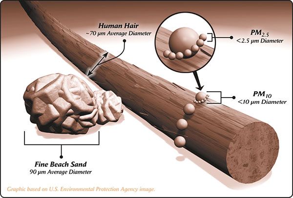
I’ve included some basic oil filter facts for reader clarity:

Image courtesy of Robert J Tracy and used with permission
The Common ISO Test Types:
ISO 16889
A multi-pass filtration performance test with continuous contaminant injection for hydraulic fluid power filter elements; a procedure for determining the contaminant capacity, particulate removal and differential pressure characteristics; a test currently applicable to hydraulic fluid power filter elements that exhibit an average filtration ratio greater than or equal to 75 for particle sizes less than or equal to 25 µm(c), and a final reservoir gravimetric level of less than 200 mg/L; and a test using ISO medium test dust contaminant and a test fluid.ISO 4548-12
is derived from the ISO standard for multi-pass filter testing (ISO 16889) which is based upon testing of hydraulic filters. This test requires filter manufacturers to determine the average particle sizes which yield Beta ratios equal to 2, 10, 75, 100, 200, and 1000, using the multi-pass test stand approach. The multi-pass test bench must contain On-Line Liquid Automatic Optical Particle Counters and calibrated using certified calibration fluid with a known particle size distribution. Particle counts are taken upstream and down-stream every minute of the test. The new standard gives a better interpretation of a filter’s overall performance.
What does the word micron (μm) mean?
The word micron is another term for micrometer (1 millionth of a meter). A micrometer is a unit of linear measure in the metric system used to measure distance from one point to another. It is used like the inch, foot, centimeter and millimeter to measure length, width or diameter of objects. Its scientific notation is μ. Some linear equivalents are 1 inch is 25,400 microns and 1 micron is .000039 inches.
Nominal vs. Absolute Filtration:
A filter is considered nominally efficient at a certain micron level if it can remove 50 percent of particles that size. In other words, a filter that will consistently remove 50% of particles 20μm or larger is nominally efficient at 20μm.
A filter is considered to achieve absolute filtration efficiency at a certain micron level if it can remove 98.7% of particles that size. So, if a filter can remove 98.7% of particles 20μm or larger, it achieves absolute efficiency at that micron level.
Current consensus on Bob is the Oil Guy.com is that 10-20μm particles cause the most wear.
Diameter of average human hair 70μm
Lower limit of visibility (naked eye) 40μm
White blood cells 25μm
Talcum powder 10μm
Red blood cells 8μm
Bacteria 2μm
Carbon black 0.6μm
Tobacco smoke 0.5μm
So, most filters you can source that are not considered high efficiency filters will probably not achieve absolute efficiency until the particulates hit around 30μm. Typically, high efficiency filters will achieve absolute efficiency to about 10μm and are nominally efficient to 5μm. The human eye can see to approximately 40μm, so we are talking some pretty small particles here. A FRAM will have a nominal micron rating around 33-40μm depending on the filter, with a WIX for the Evo having a micron Rating of 20μm. These are nominal ratings (50% efficiency). In comparison, the AMSOIL EA series is rated at 20μm absolute.
Some general rules of thumb regarding oil filters:
Filters with low capacity and high efficiency will tend to accumulate contaminants quickly and trip the by-pass value which means it’s no longer doing you any good. These filters should generally be changed every 5,000 miles for sure.
Filters with high capacity and low efficiency can hold a lot of contaminants, but will definitely not protect your motor to the same degree, as more particulates will be circulating through the motor.
Filters that are both low in capacity and efficiency will cause increased wear and shorter motor longevity if used for a prolonged period.

Last edited by golgo13; Mar 11, 2014 at 05:03 PM.


 Nov 22, 2012, 10:57 PM
Filter specs:
| WIX | |
| Manufacturer: | WIX |
| Part Number: | 57092 |
| Media Type: | Cellulose |
| Micron Rating: | 20μm Nominal |
| By-pass Valve Rating: | 14psi |
| Flow Rate: | 9-11gpm |
| Burst Pressure: | 330psi |
| Media Surface Area: | 120 sq in |
| Pleat Count: | 46 |
| Drain Back Value Material: | Nitrile |
| Country of Manufacture: | Mexico |


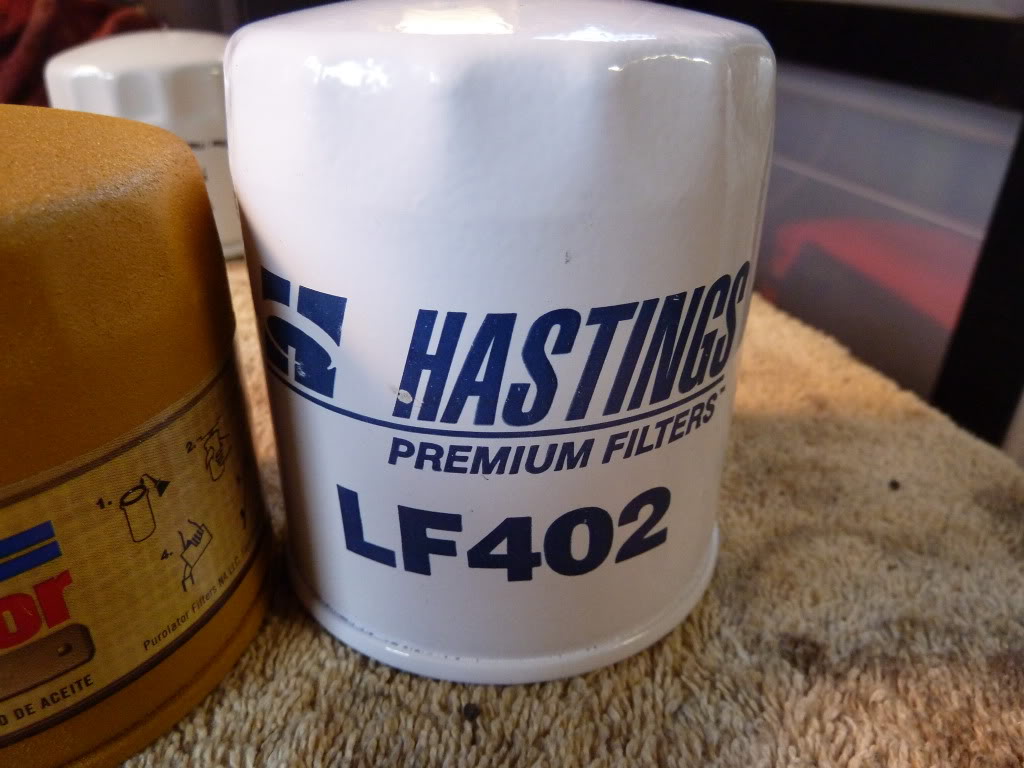
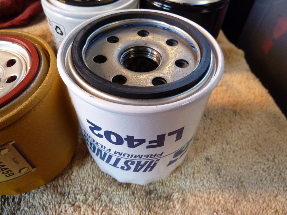
| Hastings | |
| Manufacturer: | Hastings |
| Part Number: | LF402 |
| Media Type: | Cellulose |
| Micron Rating: | 18μm Nominal |
| By-pass Valve Rating: | 18-20psi |
| Flow Rate: | 5gpm |
| Burst Pressure: | 200psi |
| Media Surface Area: | 120sq in |
| Pleat Count: | 45 |
| Drain Back Value Material: | Nitrile |
| Country of Manufacture: | USA |


| K&N | |
| Manufacturer: | Champion Laboratories |
| Part Number: | PS-1010 |
| Media Type: | Cellulose |
| Micron Rating: | 20μm Nominal |
| By-pass Valve Rating: | 11-17psi |
| Flow Rate: | 9-11gpm |
| Burst Pressure: | 300psi |
| Media Surface Area: | 105 sq in |
| Pleat Count: | 47 |
| Drain Back Value Material: | Nitrile |
| Country of Manufacture: | USA |


| Donaldson | |
| Manufacturer: | Donaldson |
| Part Number: | P550162 |
| Media Type: | Cellulose |
| Micron Rating: | 39μm Nominal |
| By-pass Valve Rating: | 11-17psi |
| Flow Rate: | 5gpm |
| Burst Pressure: | 300psi |
| Media Surface Area: | 113 sq in |
| Pleat Count: | 56 |
| Drain Back Value Material: | Silicone |
| Country of Manufacture: | USA |


| Mitsubishi | |
| Manufacturer: | DENSO |
| Part Number: | 150-1010 (Mitsubishi# MZ690116) |
| Media Type: | Cellulose |
| Micron Rating: | 40μm Nominal |
| By-pass Valve Rating: | 13psi |
| Flow Rate: | *UNKNOWN* |
| Burst Pressure: | *UNKNOWN* |
| Media Surface Area: | 109 sq in |
| Pleat Count: | 43 |
| Drain Back Value Material: | Silicone |
| Country of Manufacture: | Thailand |


| Mobil 1 | |
| Manufacturer: | Champion Laboratories |
| Part Number: | M1-110 |
| Media Type: | Cellulose + Synthetic Blend (Polyester) |
| Micron Rating: | 25μm Nominal |
| By-pass Valve Rating: | 13psi |
| Flow Rate: | 3gpm |
| Burst Pressure: | 300psi |
| Media Surface Area: | 105 sq in |
| Pleat Count: | 49 |
| Drain Back Value Material: | Nitrile |
| Country of Manufacture: | USA |


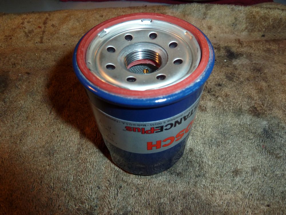
| Bosch | |
| Manufacturer: | Purolator |
| Part Number: | D3323 |
| Media Type: | Cellulose + Synthetic Blend |
| Micron Rating: | 30μm Nominal |
| By-pass Valve Rating: | 14-18psi |
| Flow Rate: | 9-11gpm |
| Burst Pressure: | 500psi |
| Media Surface Area: | 64sq in |
| Pleat Count: | 53 |
| Drain Back Value Material: | Silicone |
| Country of Manufacture: | USA |


| Purolator | |
| Manufacturer: | Purolator |
| Part Number: | PL14459 |
| Media Type: | Cellulose + Synthetic Blend |
| Micron Rating: | 20μm Nominal |
| By-pass Valve Rating: | 12-15psi |
| Flow Rate: | 9-11gpm |
| Burst Pressure: | 300psi |
| Media Surface Area: | 102 sq in |
| Pleat Count: | 61 |
| Drain Back Value Material: | Nitrile |
| Country of Manufacture: | USA |


| Royal Purple | |
| Manufacturer: | Champion Laboratories |
| Part Number: | 10-2867 |
| Media Type: | Synthetic |
| Micron Rating: | 25μm Nominal |
| By-pass Valve Rating: | 11-17psi |
| Flow Rate: | 9-11gpm |
| Burst Pressure: | 600psi |
| Media Surface Area: | 72sq in |
| Pleat Count: | 32 |
| Drain Back Value Material: | Nitrile |
| Country of Manufacture: | USA |


| AMSOIL | |
| Manufacturer: | WIX |
| Part Number: | Ea046 (deprecated) |
| Media Type: | Nano-Fiber (Donaldson Synteq media) |
| Micron Rating: | 20μm Absolute |
| By-pass Valve Rating: | 14psi |
| Flow Rate: | 9-11gpm |
| Burst Pressure: | 330psi |
| Media Surface Area: | 77 sq in |
| Pleat Count: | 35 |
| Drain Back Value Material: | Nitrile |
| Country of Manufacture: | Mexico |


| AMSOIL | |
| Manufacturer: | Champion Laboratories |
| Part Number: | Ea15k20 |
| Media Type: | Nano-Fiber (Donaldson Synteq media) |
| Micron Rating: | 20μm Absolute |
| By-pass Valve Rating: | 8-11psi |
| Flow Rate: | 9-11gpm |
| Burst Pressure: | 280psi |
| Media Surface Area: | 56 sq in |
| Pleat Count: | 32 |
| Drain Back Value Material: | Nitrile |
| Country of Manufacture: | USA |


Last edited by golgo13; Oct 17, 2014 at 10:10 AM.
A few things to keep in mind:
I don’t have the hundreds of thousands of dollars to purchase the same equipment the ISO testing group uses.
It is a single pass simple bench test using an equal contaminant to oil ratio per filter at room temperature with gravity drawing the filtrate through the media.
- This is not a test to give percent efficiency at a certain particle size.
- This test is not an official SAE or ISO test that filter manufacturers use to rate their oil filters.
- This is just a simple bench test to give a visual comparison of how easily contaminants passed though the media elements with the oil, and approximately how easily cold oil passed through as well.
Every effort was made to keep things even and fair within the limitations of the testing procedure. I had no favorites going into the testing. I believe the results are quite reasonably valid and seem to correlate well with the comparative filter efficiency ratings given by the manufacturers who publish these ratings.
Obviously, this test will not include the same heat and pressure as found in the 4G63/4B11 motor, so take that into consideration.
The Goal:
To obtain a visual representation of single pass filter efficiency while keeping the testing parameters consistent between each filter within the scope of the test. Using a filtrate contaminated with particles at or below the size known to cause increased wear to the motor (10-20μm), we should visually see how much filtrate was allowed to pass through the media.
The Procedure:
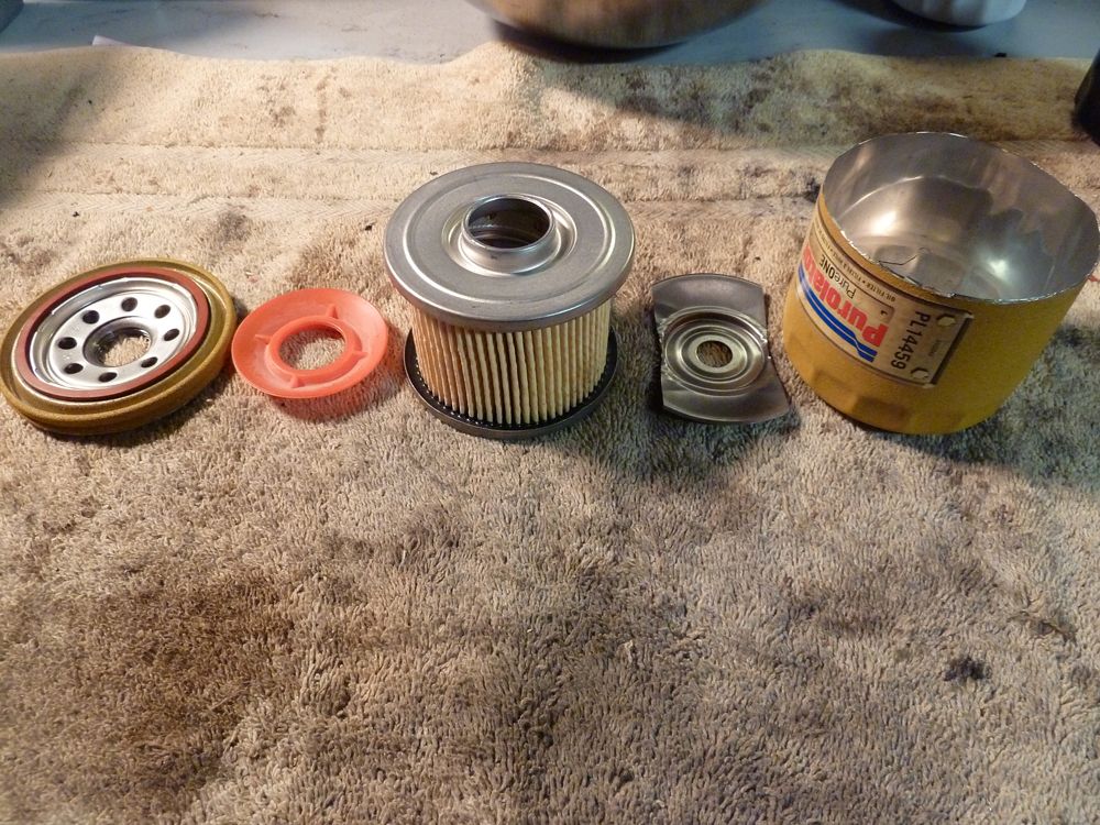
Each filter was carefully cut open along the baseplate with a dremel using a cutting disc to extract the media without damaging it. Filters that were open on each end were sealed with water tight caulk and a sheet of clear acrylic to allow for oil to only enter the center tube by passing through the media.
Each filter was then placed in a beaker containing intentionally contaminated synthetic motor oil with a 50/50 mixture of flour 1-100μm and talc ~10μm. These filters were done twice prior to the final results you see below, as this was necessary to allow for the media to be completely saturated with oil and contaminants. Since some of the filters contain more surface area and media of different thicknesses, I wanted to make sure that each filter was completely saturated to allow for a more accurate sample.
The filtrate was stirred prior to filling the beaker and placing in the filter to ensure enough particulates were diffused through the oil as gravity and air pressure worked to push the filtrate through the media.
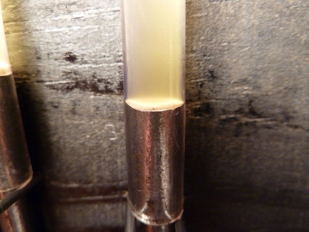
Each sample was collected using brand new 12″ sections of 3/16″ O.D. clear vinyl tubing with a syringe stuck into the opposite end. Once the center tube was filled at the same level as the surrounding filtrate, I gently stirred the contaminated oil in the center tube and then pulled on the syringe to draw a sample. I promptly plugged the business end of the tube with some nails I had previously cut in half and then the other end with the head of the nail.
Once plugged, each tube was cleaned and then hung to allow for gravity to pull the particulates to the bottom of the sample in each respective tube. The samples were allowed to sit for 48 hours prior to taking pictures of the piles of particulates.


The Results:
WIX 57092

NOTES: This seems to be the average amount of particulate for a cellulose media oil filter.
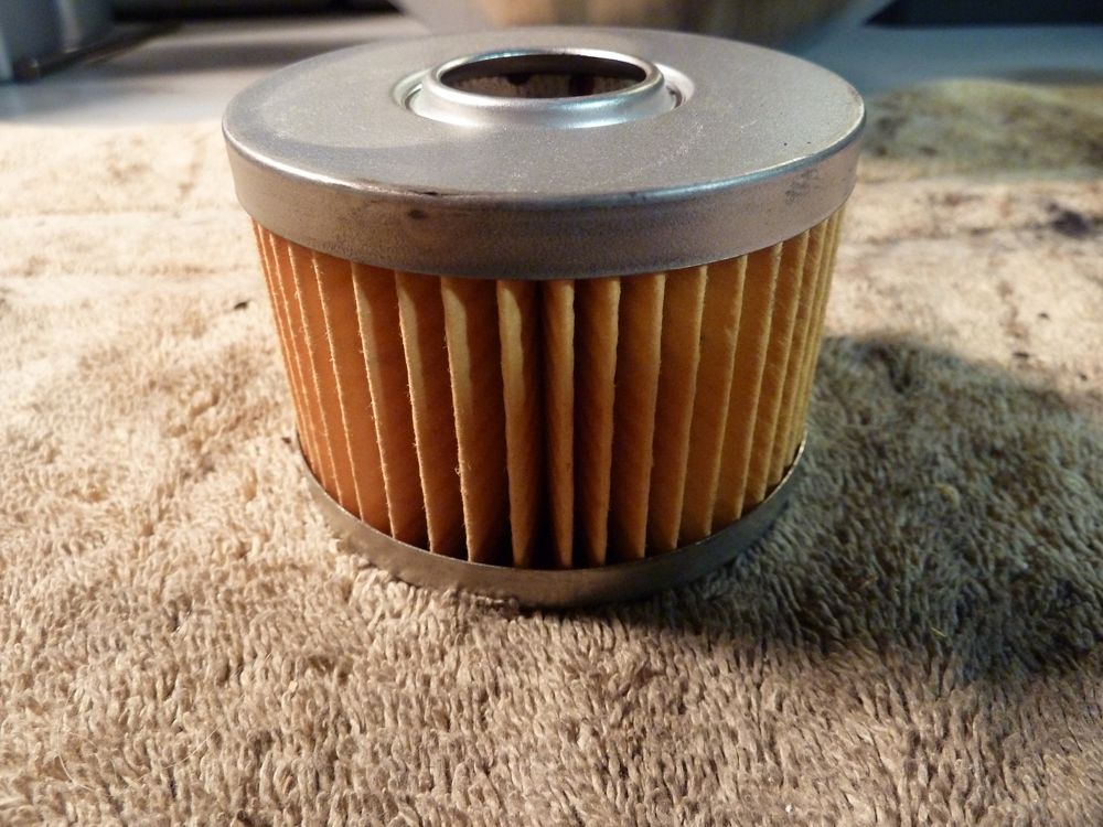
Hastings LF402

NOTES: As with the WIX filter, this is average. Nothing to write home about.
K&N PS-1010

NOTES: I guess you pay for the name when you buy K&N? I want a filter that works, not just a name. That amount of particulate looks pretty average to me.
Donaldson P550162

NOTES: Disappointing filtration. I was hoping even with cellulose media that the Donaldson was going to perform better.
Mitsubishi/DENSO 150-1010

NOTES: Lots of people trust OEM (Hell, I’m one of them) but after this test I’ll suggest something other than DENSO.
Mobil 1 M1-110

NOTES: Lots of people swear by Mobil 1. Looks like average filtration to me. This coupled with the poor construction of the filter itself means I won’t be running this filter anytime soon.
Bosch D3323

NOTES: Filter sent to me by TommiM for testing. For a blend, it fell below the Purolator, but performed better than the Mobil 1. I would consider this to be an “average” filter and since it’s being marketed as a Distance Plus filter, I would have expected better filtration, personally. The Regional Manager I spoke to on the phone said this filter is good for 12,000 miles so take that FWIW.
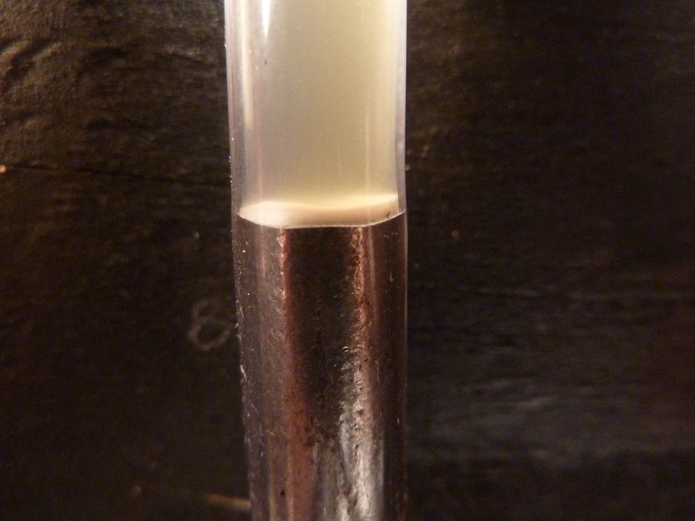
Purolator PL14459
NOTES: Impressively low particulate amount here. The cellulose and synthetic blend looks to be doing its job.
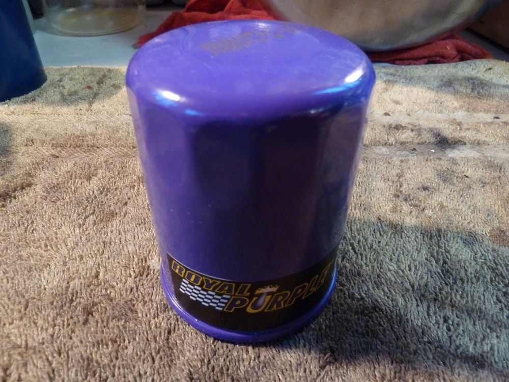
Royal Purple 10-2867

NOTES: Same construction as the other Champion Labs filters I tested, but the gentleman I spoke with on the phone claims it’s rated to withstand race conditions. The filtration was very good, on par with the AMSOIL filters I tested below. The wire mesh that lines the filter element is the exact same as that used in AMSOIL Ea15k20, which isn’t surprising since they’re both made by Champion Labs.
AMSOIL Ea046
NOTES: That old adage of, “You get what you pay for” couldn’t be any closer to the truth. Excellent filtration for sure.

NOTES: The wire holding this filter media was a bit thinner than their newer stuff, but the media was quite durable. Not as durable as cellulose, but it didn’t fall apart when I cut out a sample with a razor blade. The down side to having this wire mesh, is that it takes up room inside the filter which would probably account for the smaller surface area of this filter when compared directly to the cellulose media version of the same WIX filter.
AMSOIL Ea15k20

NOTES: Like its older brother above, this filter does its job for sure. I just don’t like the poor quality of filter construction offered by Champion Laboratories. 

NOTES: The wire mesh seems to really hold the media together. As I was cutting out a media sample for measurement, the media literally fell apart. I wasn’t very happy to see that, but that must explain for the thicker wire, as I couldn’t cut through it with a razor blade.


Conclusion:
I’ll start by saying that I’m pretty happy I did this, as it validates quite a few of my assumptions surrounding filtration efficiency and just who was making filters for whom. AMSOIL is worth the money, so all you guys slanging AMSOIL (apagan01, I’m looking at you) keep on, keepin’ on. The Royal Purple filter is also a synthetic, so if you can source one for less than the current AMSOIL filter, you may want to consider it.
I was surprised by just how good the Purolator filter actually was. Being a cellulose + synthetic blend would account for it’s filtering efficiency. I think the quality of filtration combined with the surface area of the Purolator filter and the price makes it a really good option for sure. I will say that the quality of construction of the Purolator was quite poor, even the filter arrived with a huge dent in the side. Once I cut it open, I could see just how thin the housing was. Since the filters in the 4G63 sit so low to the ground, all it would take to pop that filter would be a single rock bouncing off the ground if you’re not running an under tray.
I was disappointed to see the Mobil 1 filter performing as poorly as a cellulose filter (K&N comes to mind, since they’re both made by Champion Laboratories), even though it is also a synthetic blend similar to the Purolator. I also found that the filter construction from all of the Champion Laboratories were pretty poor. I’m saddened by the fact that AMSOIL switched to them to build their current Ea15k20, as that’s the filter they now stock.  If you can get your hands on an Ea046, that’s the filter to get. The lack of surface area in the Ea046 is a bummer, but the filtration quality makes it totally worth it.
I had expected the DENSO to perform poorly and it didn’t disappoint. The construction of the filter felt pretty decent, but looking at the internals and the filter design lead me to believe that it wasn’t going to do well. I will say that having all of that surface area will allow you to catch quite a bit of contaminants, but what good will that do if it’s only catching particulates over 30μm?
The other filters I was pulling for were just average. The WIX, Donaldson and Hastings seem to be sort of middle of the road filters that will do the job just fine if you’re okay with settling for average. The surface area of the WIX and Hastings beat out the Donaldson and the higher flow rate of the WIX beats out the Hastings. The quality of construction of all three is top notch. These filters should be fine for your average daily driven car that would see regular oil change intervals.
Additional resources:
http://www.gmtruckcentral.com/articl…lterstudy.html
Last edited by golgo13; Oct 17, 2014 at 10:24 AM.