Blueprint Series: Measuring and Setting Bearing Clearances
If we had to choose one operation that epitomizes the process of engine blueprinting – we can’t think of a better one than setting bearing clearance. This goes far beyond slapping a set of new bearings in the main saddles, torquing the main caps in place, and hoping the crank turns over. Blueprinting clearance means establishing a clearance that is your target number and working the components until this number is achieved. Anything else is just bolting an engine together.
We won’t get into establishing specific clearance goals here because that has been previously covered by EngineLabs. We can offer the standard advice that is tried and true – multiply the crank journal diameter by 0.001-inch. As an example with a small-block Chevy main journal of 2.200-inch – then an oil clearance of 0.0022-inch would be a great place to start.
This discussion will focus on main and rod bearings in a mild, street-driven performance engine that might see occasional high-RPM use, like at the drag strip. Perhaps the first bit of information worth mentioning is that this is the total clearance around the circumference of the bearing. So in the case of a 2.500-inch main bearing with a vertical clearance of 0.0025-inch, this establishes there is only 0.00125-inch clearance between the crank journal and the main bearing at the top and bottom. Under maximum load, the oil is squeezed into a very tiny area of clearance measured with five digits to the right of the decimal point–perhaps as tight as 0.00025-inch. The remainder of the clearance is found on the unloaded side–the top side of the main bearing or the bottom side of a rod bearing.
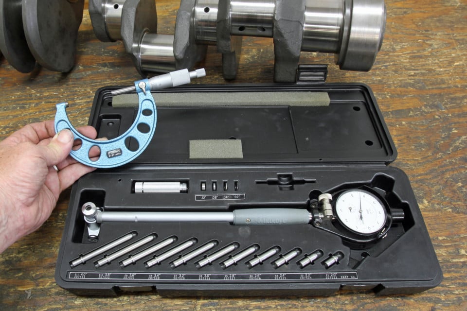
In order to do this job properly, you will need some accurate measuring tools. A minimum of a 2-to-3-inch inside micrometer and a dial bore gauge are necessary. Be sure the micrometers and dial bore gauges will measure down to 0.0001 inch. Cheaper tools often only measure down to 0.001 inch. This is not precise enough by a factor of 10. You will also need a torque wrench and sockets.
The large amount of bearing clearance on the opposite side of the load is used to feed oil between the journal and the bearing, which is why producing sufficient clearance is so important. It is this dynamic loading of the bearings that reinforces why attention to detail is so important. There are other considerations such as bearing crush, eccentricity, and bearing materials that demand close scrutiny, but we will focus on how a DIY builder can create professional results by using high-quality measuring tools and working carefully.
We will make some very important assumptions that the block and crankshaft have either been machined or carefully measured to ensure they are straight, with minimal taper, so that our measurements will pay off with a happy engine when assembled.
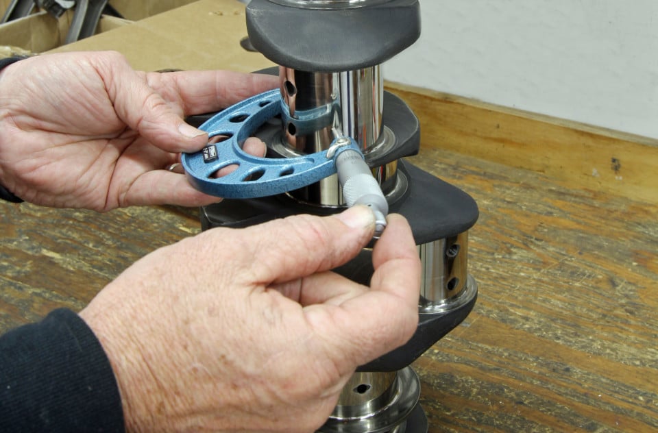
Creating the desired bearing clearance starts with accurately measuring the journal diameter. In this case, we’re measuring a big-block crank main journal. The only accurate way is to use a micrometer that measures down to 0.0001-inch.
The first order of business is to measure the crankshaft. We will need a quality outside micrometer, a notebook to record the readings, and a clear, clean work bench. The crank should be clean and ready for assembly. Assuming we’re working with a V8 engine, it’s important to measure the main journals in two locations and record both. If you are really fastidious, it’s a great idea to measure for taper across the journal as well.
Once a journal diameter is established, there are two ways to go about setting up your dial indicator to measure the inside diameter of the bearing housing.
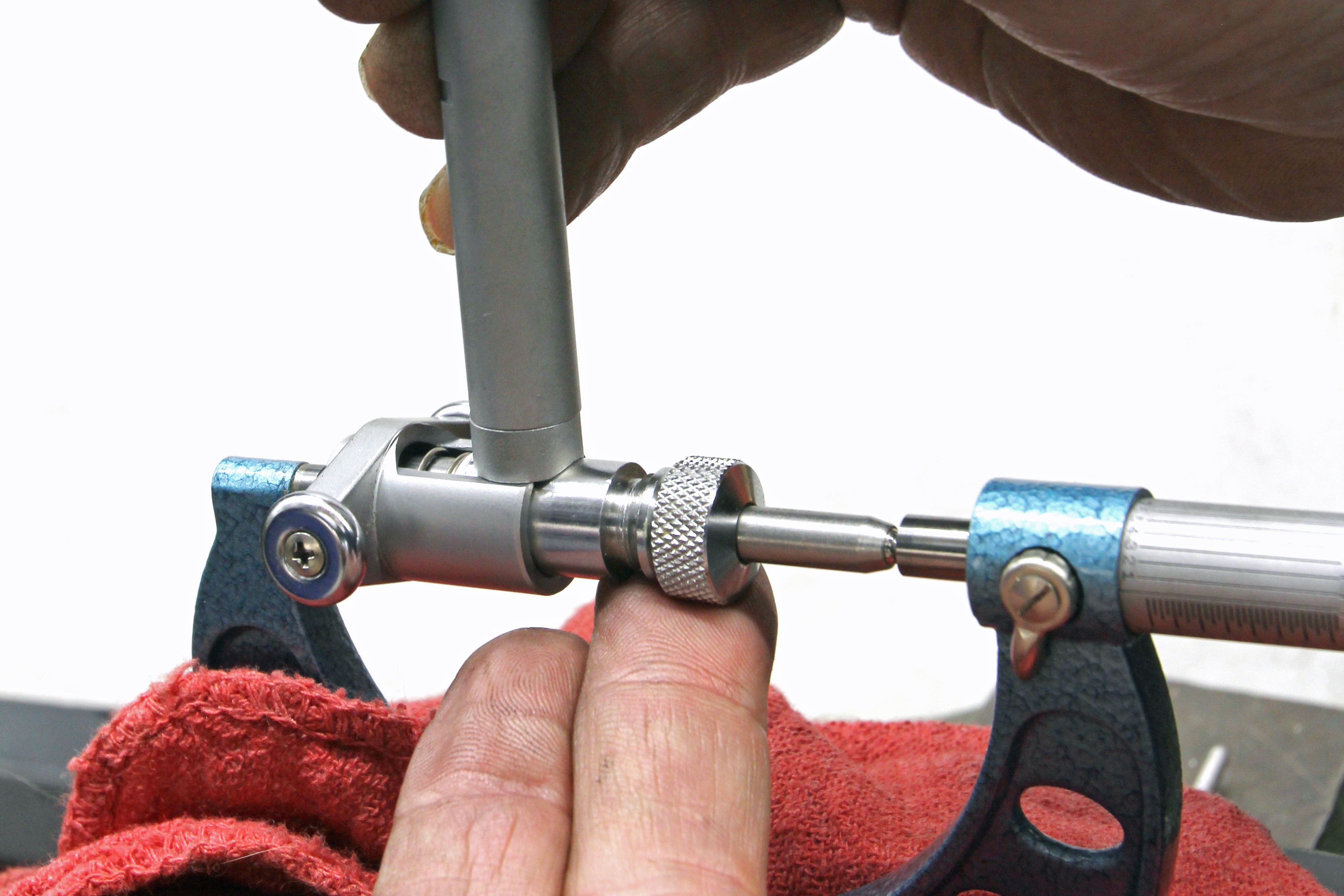
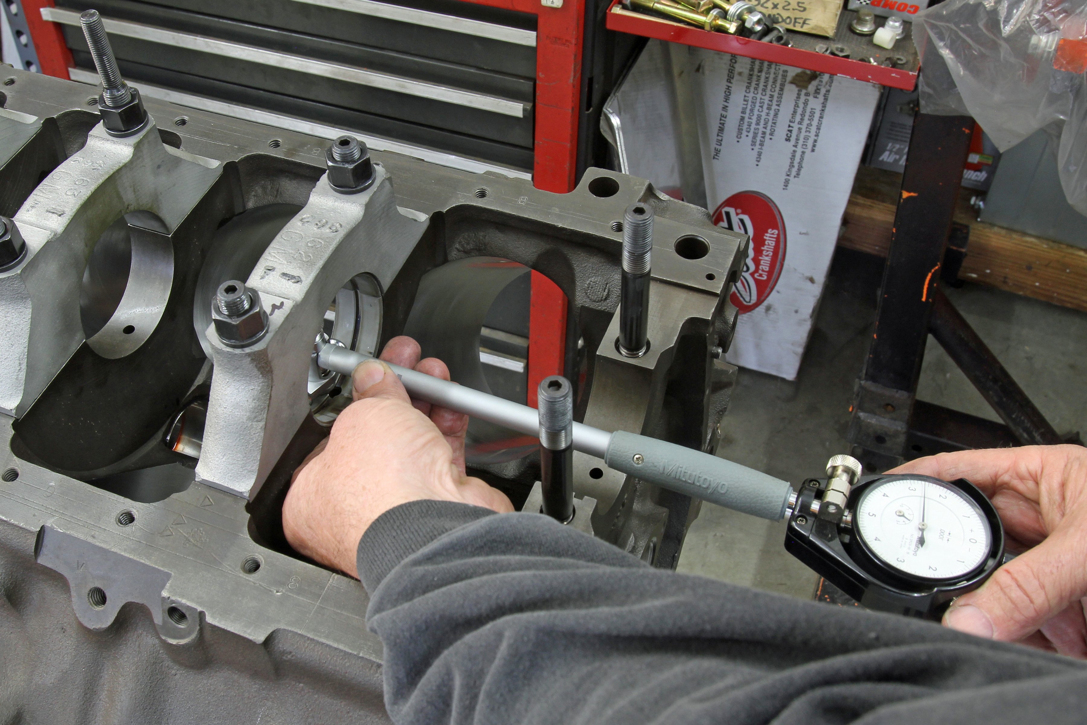
With the micrometer at a specific journal diameter, use this to zero the dial bore gauge (left). We placed our mic in a bench vise to hold it firmly, protected by a thick rag. Setting the dial bore to zero requires attention-to-detail to make sure the zero is accurate. If you induce an error at this stage, every other measurement will be in error. Next, use the dial bore gauge to measure the inside diameter of the housing bore, in this case, the number two main journal that has been torqued (right). For maximum accuracy, measure bearing clearance only in the vertical. Also check for taper in the rod. We had a poorly resized used rod that had 0.0015-inch taper. This is caused when the rods are not switched on the mandrel and only honed from one side. This creates a taper or bell-mouth in the rod big end. So always check for taper on rebuilt rods.
One way is to set the outside micrometer to a specific journal diameter. Let’s use a 454ci big-block Chevy as an example. With a 0.010-inch-under crankshaft, we measured the number three journal at 2.7387-inch. This is exactly 0.010-inch undersize. We can set the dial bore gauge to read zero at this point and then install and measure the inside diameter of the bearings in the number three main.
The second procedure saves time but could introduce a math error. This process measures all the journals. Then the builder sets the dial bore gauge to one journal size and performs the math to adjust the clearance from the dial bore gauge for the different housing bore diameters. As an example, if we set the dial bore gauge to the 2.7387-inch diameter of journal three, then we would add or subtract the difference of varying sizes of the journals to produce the actual bearing clearance. If the journal is larger than our standard by 0.0002-inch, then we would subtract 0.0002 from the dial bore gauge reading for clearance for that main bearing.
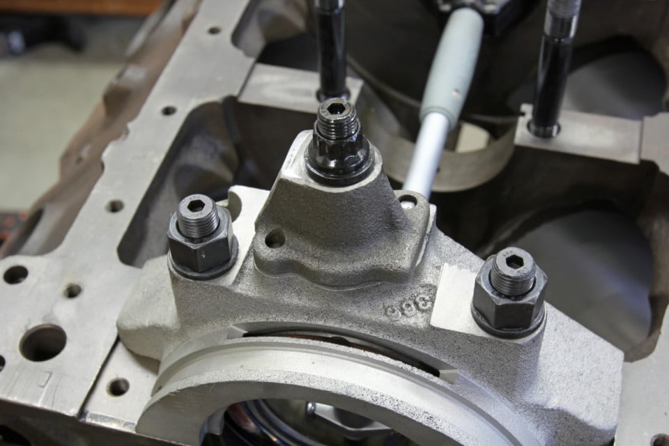
We made a simple oil pump adapter for this big-block and mounted it using the stud and nut we planned to use in the engine. We measured clearance before and after torquing this in place and discovered the clearance increased in this situation by .0008-inch!
As an example, if we installed 0.010-under bearings and measured the clearances and all was right with the world, the dial bore gauge should read +0.0025-inch (our desired clearance) for all five main journals. But this only happens on TV car shows and magazine engine articles. In a big-block that we recently assembled for a friend, the crank main journals measured as follows:
|
Main Journal |
Journal Diameter |
Actual Undersize |
|
1 |
2.7393 |
0.0094 |
|
2 |
2.7390 |
0.0097 |
|
3 |
2.7387 |
0.0100 |
|
4 |
2.7384 |
0.0103 |
|
5 |
2.7383 |
0.0104 |
None of the crank main journals measured the same and only number three was the technically correct 0.010-inch undersize. Budget and time limitations prevented us from grinding this crank 0.020-under. Instead, we had to deal with this and use multiple size bearing shells to bring the clearances as close as possible.
Let’s first address the clearances for the 0.010-under number three. Measuring the actual clearance using 0.010-under Federal-Mogul bearings, we came up with 0.0027-inch. This was slightly more than our ideal 0.0025 spec but acceptable. The other four created either too much or too little clearance using just 0.010-under bearings.
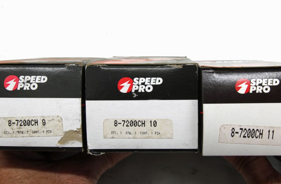
Most race bearing manufacturers will offer bearings in +/- sizes. For example, Federal Mogul offers main and rod bearings in 0.001-inch under and oversize versions within the lineup of standard, 0.010-inch, 0.020-inch undersized bearings. That allows you to set the clearance by adjusting, even with half-shells.
Some performance bearing companies like Federal-Mogul offer optional bearing sizes such as 0.001 undersize or oversize inserts that make it much easier to set an ideal clearance. In our case, we needed 0.011-inch undersized on some of the journals and 0.009-inch-undersized bearings for the front two. Federal-Mogul offers these and saved our bacon. This allowed us to increase or decrease the clearances to get closer to our ideal. While mixing half-shells is acceptable practice, never mix shells with more than 0.001-inch spread and always stay within the same manufacturer. In other words, never mix a 0.009 bearing shell with an 0.011-inch version.
One down side to performing all these customized clearances is that we were faced with purchasing two (and in our case, three) sets of main bearings for one engine. So do all measuring before you buy the bearings. The same is true with rod bearings.
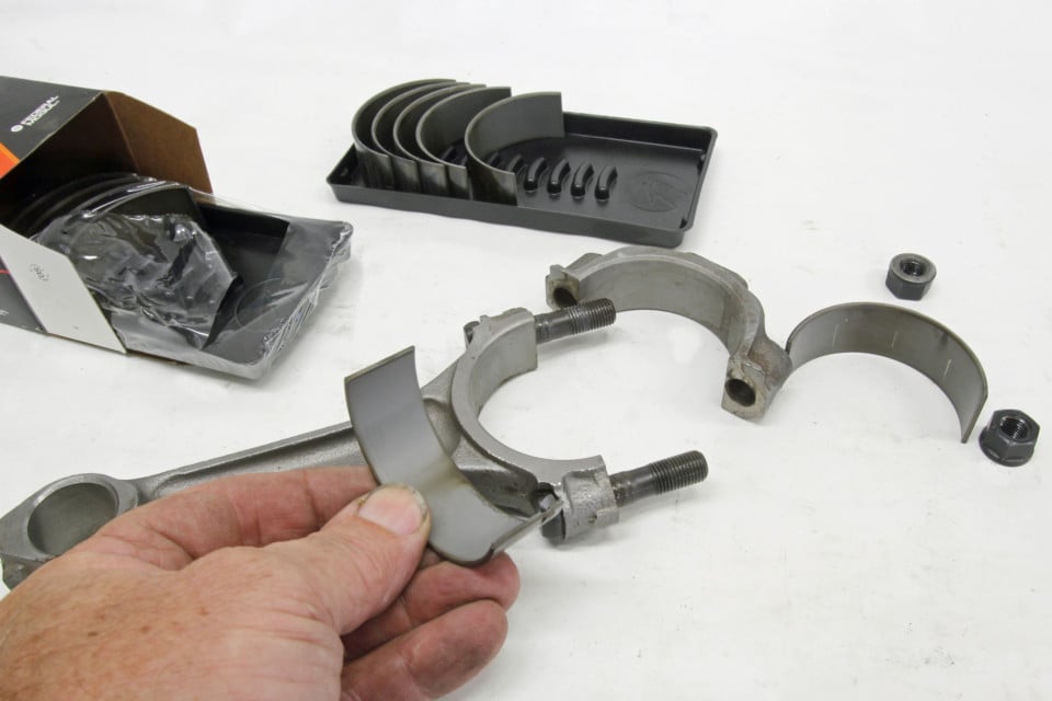
It is accepted practice, for example, to mix one 0.010-under shell with an 0.011-under bearing half on a specific rod or main journal to achieve the desired clearance. Never mix bearings of different manufacturers and never mix bearing halves that are more than 0.001-inch different in size.
The best way to fix this would have been to have the engine align honed to establish the proper housing bore diameter. In our case, the engine had to go back together due to deadlines beyond our control so we did the best we could. The final 0.0035-inch clearance is well within factory tolerances, but it is also 0.0005 inch wider than we would prefer. For a mild street motor, this was acceptable. Another reason this will work is that as the thrust bearing, this additional clearance will provide more than enough oil to properly lube the bearing’s thrust surfaces.
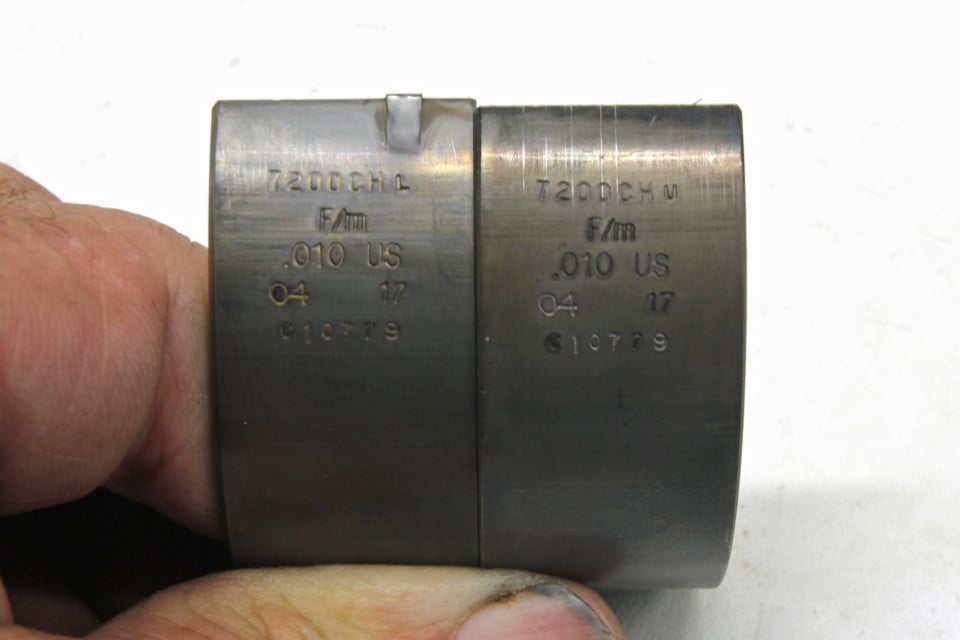
These are Federal-Mogul 0.010-under rod bearings. Note the stamp “L” or “U” on these shells along the upper stamping. The “L” means this shell must be installed in the lower half of the connecting rod so that the bearing’s chamfer will be on the same side as the crank radius. The “U” obviously is the upper insert. If the bearings are inverted, the chamfer will not be adjacent to the crank journal radius and the bearing may rub. This isn’t a major issue, but certainly something to watch carefully.
It’s also important to point out that housing bore diameter, whether it be the rods or mains, have a big effect on bearing clearance. Incorrect clearances are commonly blamed on the bearings when the reality is the housing bores are improperly sized. When combined with inconsistent crank journal diameters, this tolerance stack-up is the real culprit in nearly all clearance issues. Measuring these parts is the only way to know for sure.
At some point in the Blueprinting series, we will also look at the accuracy of the measurement tools you are using. If your measuring devices are not accurate to at least 0.0002-inch, the actual numbers may not be an accurate reflection of what is really there.
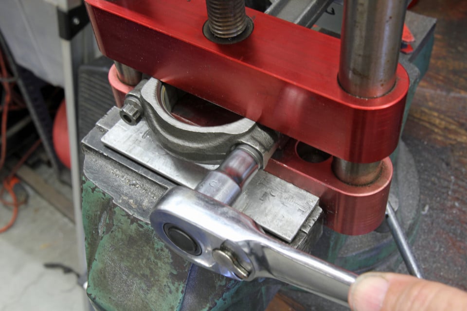
When bearings are installed in the connecting rod, always use some type of rod vise to clamp across the cap parting line. This prevents damage to the rod when the bolts are tightened. If you don’t have a rod vise, use a bench vise with aluminum inserts in the jaws to prevent damage to the connecting rod.
It’s also important to point out that bearing clearance will dictate engine oil viscosity. We will have to over-generalize here, but tighter clearances demand thinner oil while wider clearances will need a higher viscosity oil to establish the proper oil-film thickness to prevent abnormal wear.
Most of the details in this story relate to employing common sense and accurate measurement techniques. Accomplish both of those tasks and your engine will live a long and powerful life.
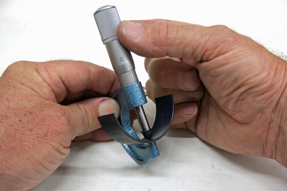
If you really want to get down into the tiniest of details, you can test bearing thickness variations. You will need a round bearing adapter for your micrometer as shown (we found ours through Grainger). However, our experience is that accuracy of measurement becomes more of an issue than variations in bearing thickness. In other words, can you accurately measure to 0.0002-inch?


