Posted on Leave a comment

Racing Helmets – Brain Bucket: What You Need To Know

The Sports Car Club of America (SCCA) runs solo events, also known as autocross events, all across the nation. The General Competition Rules (GCR) require a helmet is worn by both the driver and any passenger.

A helmet is one of those things you hope you never actually need. Many refer to this safety device as a “crash helmet” which is something you certainly never want to use it for, however that is exactly what it is designed to be utilized for. These helmets do a very important thing during a collision — protect your brain.


Even if you haven’t attended medical school, we all know enough anatomy to understand we need our brains to live. So, for obvious reasons this is no place to cut corners and try to save a few bucks. The purchase of a helmet can save your life. So, long story short, spend a couple of dollars on your own brain bucket. It is an easy insurance policy.

Not all helmets are created equal, and they are individually designed for different tasks. Automobile racers require a Snell SA certification, SA stands for Special Application.

I often forget what my helmet is really for. I use my helmet as a place to put sponsor stickers and I use it to concentrate before a race. I close my visor, which is the universal sign for “leave me alone for a minute,” and I sit and think about the task at hand. How do I want to start? How am I going to manage my tires? Which cars am I going to draft with, or who am I going to block? My helmet is my Zen place, but that is not the intention of the design. It is designed to save my life when things go sideways, or worse, upside down.

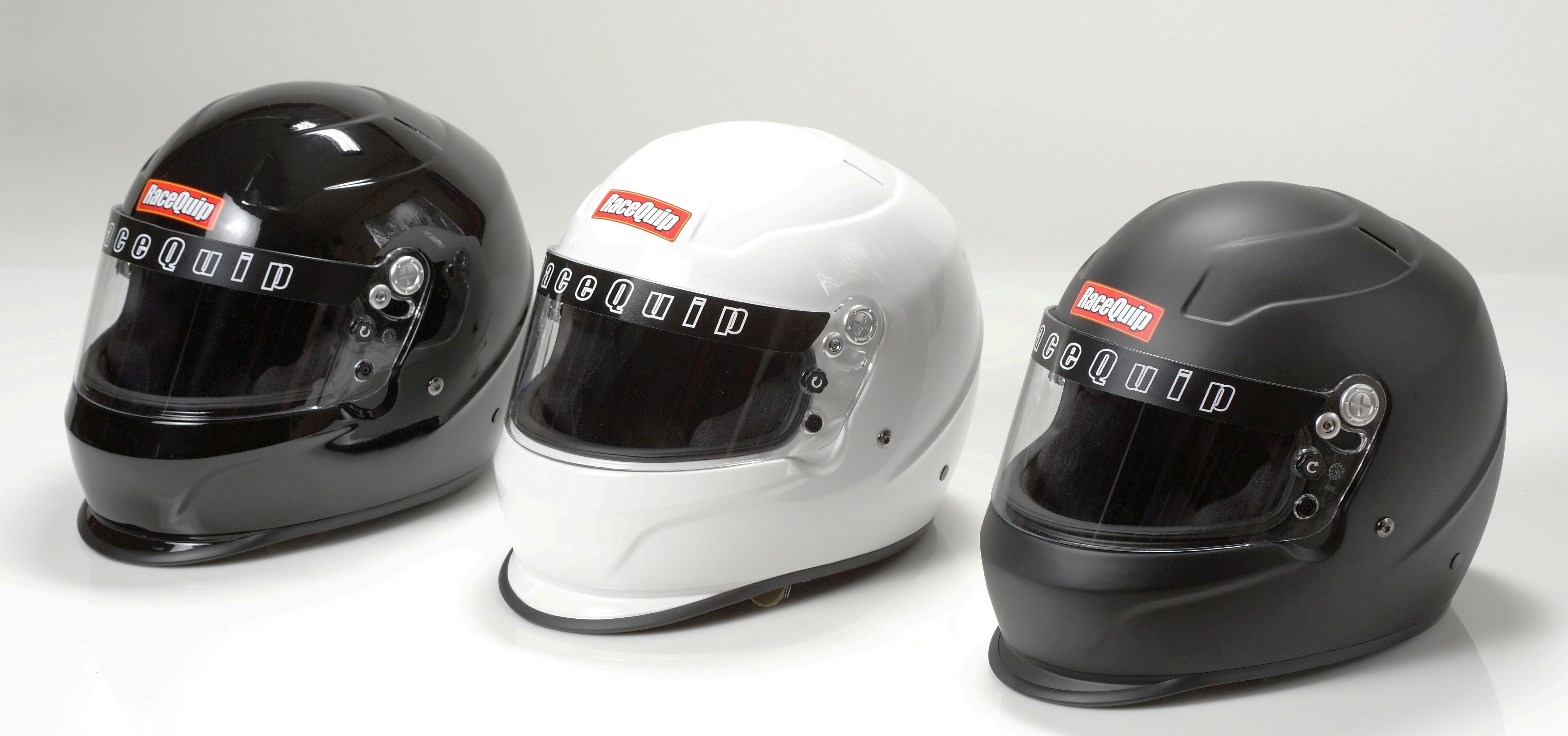
RaceQuip builds high quality yet affordable helmets for auto racing only. They don’t bother building motorcycle helmets. They are strictly in the car racing market.

Certification

When purchasing a helmet there are various options that need to be considered. The first one is the certification. For most car racing enthusiasts you are looking for a Snell SA rating. It is important to understand how helmets are rated as you will see a few different decals on helmets as you are shopping around.

You will see a D.O.T. decal which is really for motorcycle helmets on the public roads. You will see an M rating which is again for motorcycles and you will also see an SA rating. The SA rating also comes with a year associated with it. The year listed on the decal isn’t the year the helmet was manufactured, it is the Snell standards associated with that particular year. You may also run across F.I.A. ratings which come out of Formula 1 and Europe.

This helmet has a Snell SA 2000 rating, which means it is out of date. The ratings are good for approximately 11 to 12 years from the Snell date (depending on new ratings, and a particular sanctioning body’s rules). When you go through tech inspection, this is the sticker the tech inspectors are digging around inside your helmet to find.

So, how in the “snell” did this certification come about? Great question. Pete Snell died in a motor racing accident in 1956 from a rollover collision. Afterwards, a team of doctors, engineers, and scientists got together and, in Snell’s memory, dedicated their work to certifying safety standards in helmets. Since 1957, the Snell Memorial Foundation has been certifying helmets. Why do you care? Because unless your helmet has their certification sticker inside, you ain’t racin’.

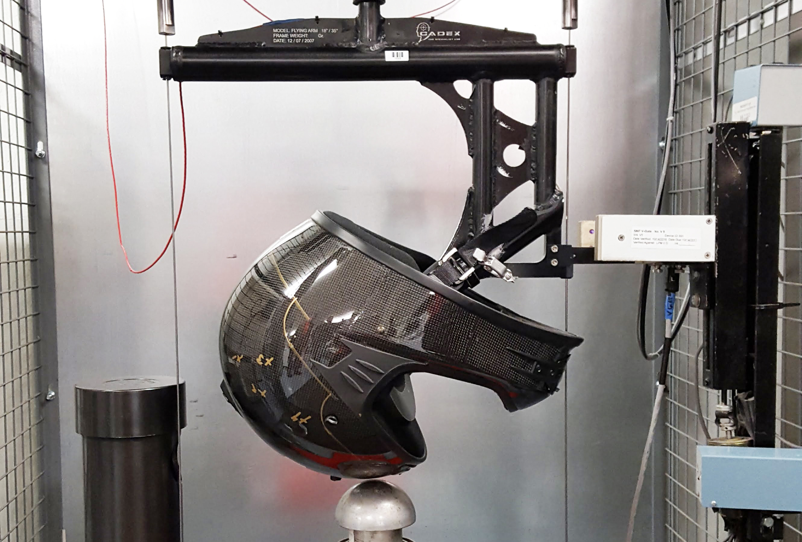
This is the drop test at the Snell Memorial Foundation, where engineers spend all day smashing stuff.

To find out how helmets can earn a Snell rating I spoke with Ed Becker, executive director and chief engineer at the Snell Memorial Foundation. The simple answer is helmets are test rated by bashing them into things. One of the tests performed is when a helmet has a 6.1 kilogram metal head placed in it (yes, kilograms because scientists use the metric system), and then the helmet is dropped from 11 feet. Sensors inside the helmet measure the G’s felt by the simulated head. No, they don’t use live humans for this test, for obvious reasons. If the G’s felt are above 243 G’s for a size large helmet, the helmet fails and does not receive a Snell certification.

Ed said helmet manufacturers have their own choice in how they build a helmet, Snell does not mandate a construction process, they only designate the tests the helmet must pass in order to be certified. The goal at Snell is “impact energy management,” which means when the outside of your helmet stops, the inside of the helmet should let your head “ride down” the impact by compressing the inner layer of the helmet, so your brain doesn’t feel the heavy hit.

For the SA 2015 standards, the SA rated helmets are being hit harder than the M rated helmets. Currently, most helmets that arrive at the foundation for testing do pass the tests as the helmet manufacturers engineer the helmets with the Snell standards in mind. However, occasionally helmets do fail, and then they are sent back to the manufacturer for a redesign. Snell rated helmets are safer, because they are tested beyond the government requirements for a basic D.O.T. rating. Those government requirements date back to standards set in 1966 which Ed considers, “Ancient technology.”

Some sanctioning bodies allow you to run an M rated (motorcycle) helmet, however, the recommendation for automobile competition is the SA rating should be used. The motorcycle rated helmets are not designed for impacts with roll cages and are not built with fire-retardant materials. The helmet in this photo, decked out in Girl Power livery, is a Pyrotech SA 2015 rated helmet for auto racing.


Construction/Fitment

Patrick Utt, president of RaceQuip, explained how his helmets are built, “Helmet construction, from inside out, starts with a layer of fire retardant cloth covering a thin layer of soft foam against your head. This covers a 2-inch thick Expanded Polystyrene (EPS) dense foam insert. The EPS liner fits into an outer shell made from one of any various composite materials including fiberglass, Kevlar, and/or carbon fiber. The outer shell has a layer of gelcoat (or clear epoxy) that was sprayed into the mold to ensure the helmet has a good surface finish and releases from the mold more easily. Lastly, a layer of fire retardant paint covers the gelcoat layer.” RaceQuip prides itself for its affordable helmet designs and only builds SA rated helmets.

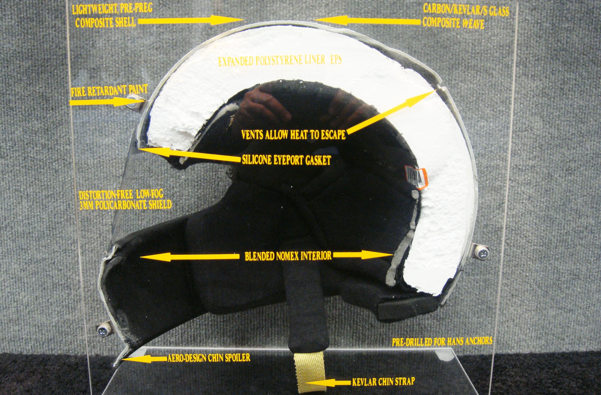
This helmet cut away shows the construction of an SA rated helmet. There is a lot of engineering in the design of these helmets to ensure you have the best chance possible in a collision.

When deciding which helmet is the right one for you, the best advice I have seen comes from Ken Myers, owner of I/O Port Racing Supplies, who races cars and sells helmets to racers all day long. “If you can go to a store and try the helmet on, you will be much better off versus buying one on the internet and hoping for the best,” he says.

Ken says fitment is the key to being comfortable in the race car. “Size large doesn’t always mean large, and a large helmet in a Pyrotech that fits you doesn’t mean a large helmet in a Bell will fit you the same,” he mentions. “Bell’s higher-end helmets are sized in hat sizes, for example 7 5/8ths. However, just because you wear a 7 5/8ths hat doesn’t mean that same helmet size will fit your head properly. You need to try the different helmets on.”

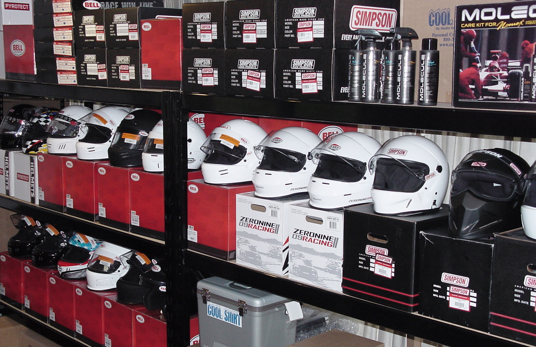
I/O Port Racing Supplies has many helmet options to choose from. According to owner Ken Myers, it is helpful to take the time to test fit different helmets before making your final decision.

One of the considerations when buying a helmet is the material the shell is made of. More expensive helmets are made of carbon fiber and are lightweight. Ken Myers says there are some advantages to a lighter helmet in a collision. “The more mass on your head in a collision, the more chance for injuries to the neck. Additionally, lighter helmets are easier on the drivers during long stints behind the wheel, like for endurance racers.”

This advice was echoed by Patrick Utt from RaceQuip, “The weight factor is mostly important to racers who spend an hour or more in the car during a race. The lighter weight is less likely to fatigue the neck muscles.”

Ken did offer this warning about lightweight carbon fiber helmets — not all carbon fiber is actual carbon fiber. “Many helmet manufacturers use a mix of fiberglass, Kevlar, and one layer of carbon fiber on the outside of the helmet to make it appear as if it is made completely with carbon fiber, which it isn’t. A $500 carbon fiber helmet, isn’t really a carbon fiber helmet.”

Ken also indicated that just because a helmet is more expensive, it doesn’t mean that it is actually a safer or better helmet, “All SA 2015 helmets have passed the same criteria to meet that Snell standard. A $250 SA 2015 helmet from Pyrotech met the same standards as a $1,300 SA 2015 Bell Carbon helmet. What matters is does the helmet meet your needs?”

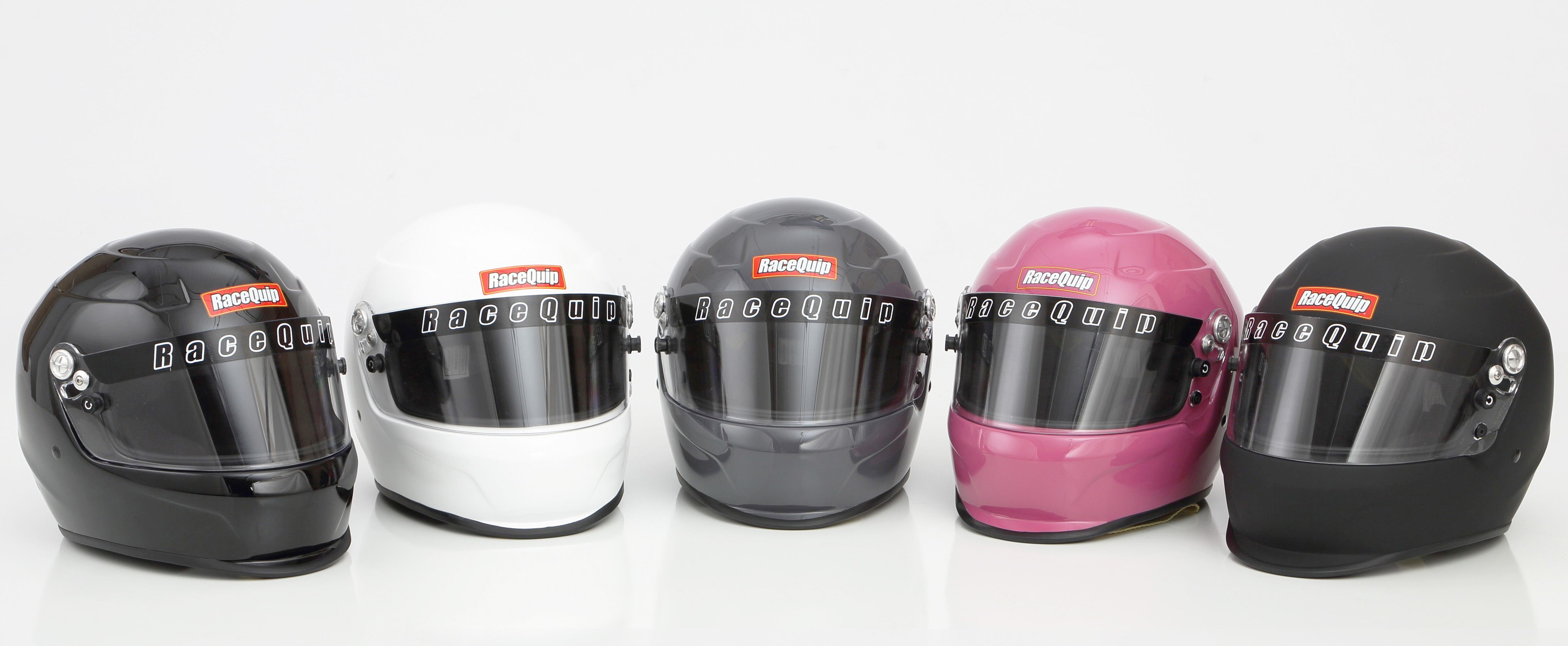
There are many different helmets to choose from. The important thing to look at when deciding is comfort and rating for usage (does your helmet fit the rules of the sanctioning body you are racing with?).

Consider Options

Other things to consider when purchasing a helmet are options. Do you want forced air into your helmet? Then you need to purchase a helmet that allows you to pipe in air. Do you race on a dirt track with a lot of dust? You may want a helmet with less air vents in the front. Do you have a radio in your car? You may want to purchase a helmet that has radio speakers already in it.

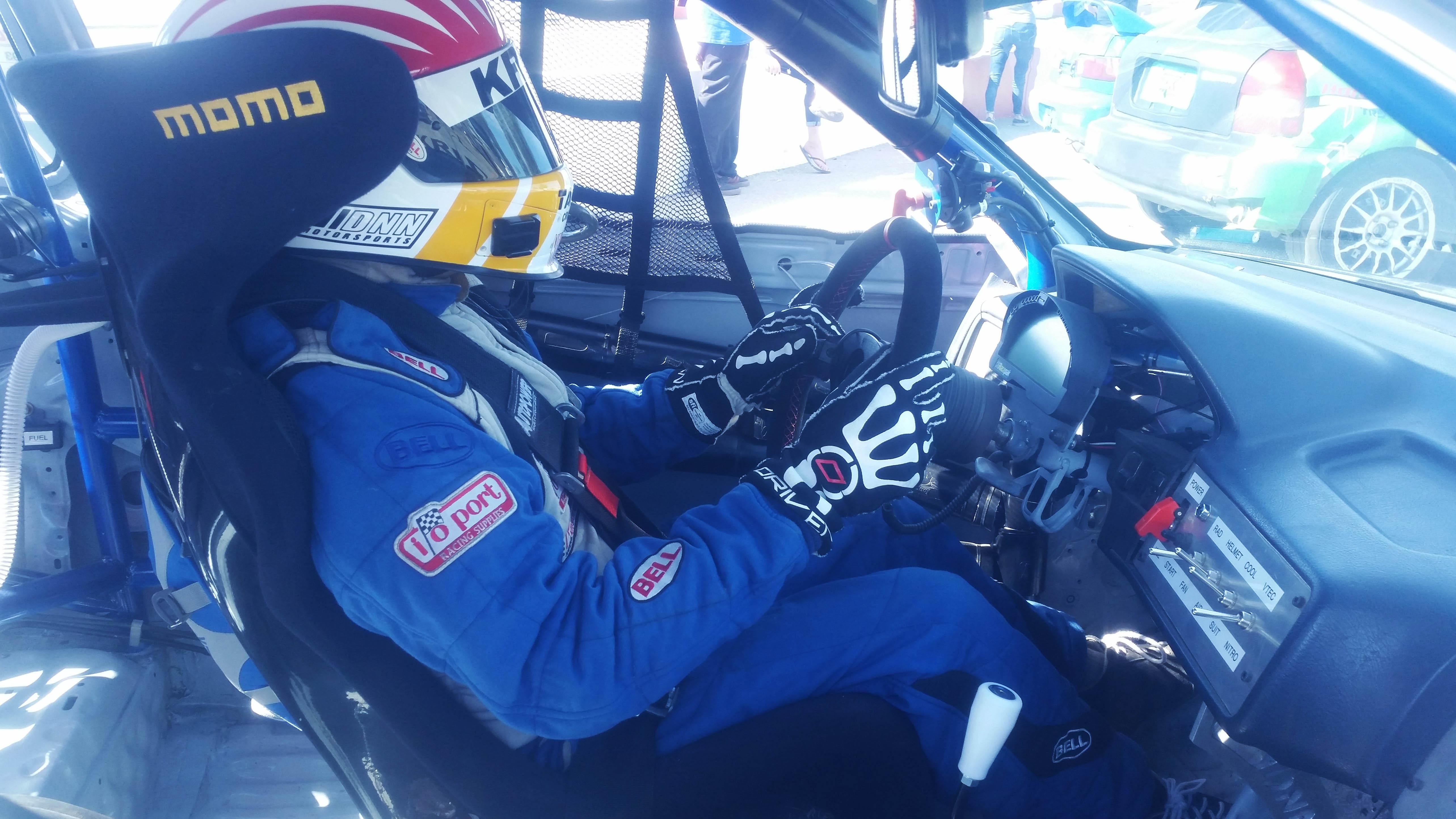
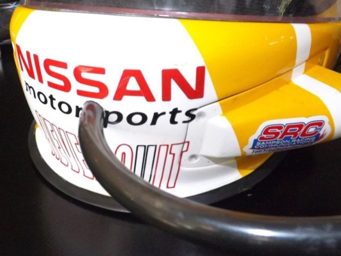
Sampson Racing Communications can add a radio to any helmet you have, however, some helmets, like this Stilo have radio communications designed into the helmet from the factory.

Shawn Sampson, racer and owner of Sampson Racing Communications (SRC) outfits teams with radio equipment and sells helmets with radio gear already installed. “I love the Stilo helmet line. It’s the helmet I wear when I am racing in the 25 Hours of Thunderhill. You don’t have to worry about ear buds coming out of your ears; the speakers are built right into the helmet. It works great.”

For you guys who get thirsty out on the track you can even modify your helmet to allow for drinking water.

Other things to consider:  if you race at night, you will want a clear face shield. If you race in a sunny place, you may want a dark or smoked shield. If you are an endurance racer and need to drink water during a race, you may need to add driver hydration to your helmet by routing a tube through the front to a camel pack with water.

There are a lot of things to consider when you make your helmet purchase, so it is crucial to think about all of these options before getting out your credit card. For example, if you are going to road race with the National Auto Sport Association (NASA), you are required to have a full-face helmet. Open-face helmets, which are used frequently in autocross events, are not allowed in wheel-to-wheel road racing with NASA. Knowledge is power — read your rule book!


Be fast and be safe. Take the time to ensure your helmet is right for you and what you intend to do with it.

All SA 2015 helmets are equipped with anchors for HANS-style head and neck restraint devices, which means it is no longer an issue that has to be decided by the customer, your helmet will come with those anchor positions already. New Snell standard helmets won’t be out until around October of 2020 with an SA 2020 rating which will provide even more advances in driver safety. Make sure the helmet you buy is right for what you need. When your car is rolling upside down at 100 miles an hour, that is no time to think to yourself, “Darn, I should have bought a better helmet.”

Good luck with your helmet shopping experience and keep the shiny side up!

Posted on Leave a comment

Supporting Your Cylinders – Open, Semi-Closed, Or Closed Deck?


You’ve more than likely heard the terms open deck, semi-closed deck (semi-open), and closed deck before. But, do you know how to identify which design your block uses or why an open-deck that works well for a naturally aspirated build won’t likely last very long if it’s boosted or has nitrous? Which design your engine has will play a major role in the maximum peak cylinder pressure your block can handle, which can be simply translated to maximum power.

Peak cylinder pressure is much greater at the top the of the cylinder, where the combustion event happens. This is in addition to any secondary pressure sources the cylinder might be exposed to, such as forced induction, nitrous, and detonation. Naturally, this is the location that most failures happen, the more pressure you introduce into the cylinder, the more likely the cylinder wall is to bubble, crack, or fail entirely.

The video above, posted by time attack team Jager Racing and featuring Outfront Motorsports, presents the advantages of using a closed deck block on their time attack Subaru WRX STI. The video focuses specifically on the EJ25 motor, but the advantages can be generalized.

Open Deck

An open deck Ford EcoBoost 3.5L V6. Notice the lack of any type of structural support around the top of the cylinders (although some open deck designs utilize a support point at the end of each outside cylinder).

An open deck is one of the most common designs found in lower horsepower aluminum blocks. It is the easiest to manufacture and provides the overall best cooling efficiency, due to the coolants ability to make full contact with the surface area of the upper portion of the cylinder. Some will argue that this block has the benefit of weighing less than its two siblings because less material is used, but this weight difference is marginal for most blocks.

The downside to an open deck is that it provides the least amount of structural support at the top of the cylinder walls, where they need it most. This reason alone makes an open deck block the least reliable choice for almost any type of forced induction or nitrous application, and should be left to low compression, naturally aspirated engines and low boost platforms.

Semi-Closed Deck

A semi-closed deck flat-four EJ25, found in the Subaru WRX STI. Notice the bridges used to help prevent any distortion around the top of the cylinders.

A semi-closed deck is the most common design found in modern factory turbocharged aluminum blocks, and is stronger than an open deck by adding structural support to the top of the cylinders at four points. Using modern casting techniques, this design can handle respectable boost levels into the mid 30 PSI range and a much higher peak cylinder pressure than an open deck (depending on the application).

Because of the added material around the cylinder walls, this style is more difficult to manufacture and requires more machine work before the cylinders can be installed. Some will argue that the added support joints of a semi-closed deck reduces cooling efficiency and is more prone to cylinder hot spots by limiting the surface area for the coolant to contact. At higher horsepower levels, a semi-closed deck is still prone to failure at the points in between the supporting joints, especially in endurance racing or road racing applications where sustained high temperatures are common.

The most common solution for semi-closed and open deck blocks is installing aftermarket sleeves that can support higher cylinder temps and pressure. This process is pretty expensive, but it is highly recommended that you find a reputable machine shop that has experience with your platform. Sleeving requires a lot of precise machine work to not damage the block, so only the best in your area should be trusted.

Left: A factory 3.5-liter EcoBoost engine prior to being machined for aftermarket sleeves. Right: A sleeved 3.5-liter EcoBoost engine.

Closed Deck

A modified closed deck flat-four EJ25, found in the Subaru WRX STI. Notice the lack of any open space around the water jackets (only coolant ports), providing full support around the top of the cylinder walls.

A closed deck design is generally left to iron blocks and aluminum racing engines. It is the perfect design for fully built, high compression, high revving race engines that require the highest level of structural support available. Common on high level drag race motors, this design is also able to withstand prolonged periods of high heat and cylinder pressure commonly seen in endurance racing and road racing.

A closed deck block is much more expensive and requires an entirely different casting procedure if done from the manufacturer, but can also be modified using pieces that are press fit into position around the water jackets. The latter process requires a custom head gasket, along with precise calculations and machine work to verify that the pieces fit properly and that the water ports are drilled properly to provide adequate flow to efficiently cool the heads.

Many will also note that a closed deck block provides the least amount of cooling capability out of the three. Although this is true to an extent, many of todays closed deck blocks have been put through extensive testing and are designed to guarantee efficient cooling.

Conclusion

Depending on the goals for your build, you may need to sleeve your block or upgrade to a closed deck design. Most modern semi-closed deck blocks can handle very respectable power levels before needing to be sleeved or upgraded, and open deck blocks can handle just about anything you throw at it in naturally aspirated form. But, if you are building a race engine and want the ultimate reliability out of your block, your best option is a closed deck design or aftermarket sleeves (depending on the application and your budget).

Posted on Leave a comment

Blueprint Series: Measuring and Setting Bearing Clearances

If we had to choose one operation that epitomizes the process of engine blueprinting – we can’t think of a better one than setting bearing clearance. This goes far beyond slapping a set of new bearings in the main saddles, torquing the main caps in place, and hoping the crank turns over. Blueprinting clearance means establishing a clearance that is your target number and working the components until this number is achieved. Anything else is just bolting an engine together.

We won’t get into establishing specific clearance goals here because that has been previously covered by EngineLabs. We can offer the standard advice that is tried and true – multiply the crank journal diameter by 0.001-inch. As an example with a small-block Chevy main journal of 2.200-inch – then an oil clearance of 0.0022-inch would be a great place to start.

This discussion will focus on main and rod bearings in a mild, street-driven performance engine that might see occasional high-RPM use, like at the drag strip. Perhaps the first bit of information worth mentioning is that this is the total clearance around the circumference of the bearing. So in the case of a 2.500-inch main bearing with a vertical clearance of 0.0025-inch, this establishes there is only 0.00125-inch clearance between the crank journal and the main bearing at the top and bottom. Under maximum load, the oil is squeezed into a very tiny area of clearance measured with five digits to the right of the decimal point–perhaps as tight as 0.00025-inch. The remainder of the clearance is found on the unloaded side–the top side of the main bearing or the bottom side of a rod bearing.

In order to do this job properly, you will need some accurate measuring tools. A minimum of a 2-to-3-inch inside micrometer and a dial bore gauge are necessary. Be sure the micrometers and dial bore gauges will measure down to 0.0001 inch. Cheaper tools often only measure down to 0.001 inch. This is not precise enough by a factor of 10. You will also need a torque wrench and sockets.

The large amount of bearing clearance on the opposite side of the load is used to feed oil between the journal and the bearing, which is why producing sufficient clearance is so important. It is this dynamic loading of the bearings that reinforces why attention to detail is so important. There are other considerations such as bearing crush, eccentricity, and bearing materials that demand close scrutiny, but we will focus on how a DIY builder can create professional results by using high-quality measuring tools and working carefully.

We will make some very important assumptions that the block and crankshaft have either been machined or carefully measured to ensure they are straight, with minimal taper, so that our measurements will pay off with a happy engine when assembled.

Creating the desired bearing clearance starts with accurately measuring the journal diameter. In this case, we’re measuring a big-block crank main journal. The only accurate way is to use a micrometer that measures down to 0.0001-inch.

The first order of business is to measure the crankshaft. We will need a quality outside micrometer, a notebook to record the readings, and a clear, clean work bench. The crank should be clean and ready for assembly. Assuming we’re working with a V8 engine, it’s important to measure the main journals in two locations and record both. If you are really fastidious, it’s a great idea to measure for taper across the journal as well.

Once a journal diameter is established, there are two ways to go about setting up your dial indicator to measure the inside diameter of the bearing housing.

With the micrometer at a specific journal diameter, use this to zero the dial bore gauge (left). We placed our mic in a bench vise to hold it firmly, protected by a thick rag. Setting the dial bore to zero requires attention-to-detail to make sure the zero is accurate. If you induce an error at this stage, every other measurement will be in error. Next, use the dial bore gauge to measure the inside diameter of the housing bore, in this case, the number two main journal that has been torqued (right). For maximum accuracy, measure bearing clearance only in the vertical. Also check for taper in the rod. We had a poorly resized used rod that had 0.0015-inch taper. This is caused when the rods are not switched on the mandrel and only honed from one side. This creates a taper or bell-mouth in the rod big end. So always check for taper on rebuilt rods.

One way is to set the outside micrometer to a specific journal diameter. Let’s use a 454ci big-block Chevy as an example. With a 0.010-inch-under crankshaft, we measured the number three journal at 2.7387-inch. This is exactly 0.010-inch undersize. We can set the dial bore gauge to read zero at this point and then install and measure the inside diameter of the bearings in the number three main.

The second procedure saves time but could introduce a math error. This process measures all the journals. Then the builder sets the dial bore gauge to one journal size and performs the math to adjust the clearance from the dial bore gauge for the different housing bore diameters. As an example, if we set the dial bore gauge to the 2.7387-inch diameter of journal three, then we would add or subtract the difference of varying sizes of the journals to produce the actual bearing clearance. If the journal is larger than our standard by 0.0002-inch, then we would subtract 0.0002 from the dial bore gauge reading for clearance for that main bearing.

We made a simple oil pump adapter for this big-block and mounted it using the stud and nut we planned to use in the engine. We measured clearance before and after torquing this in place and discovered the clearance increased in this situation by .0008-inch!

As an example, if we installed 0.010-under bearings and measured the clearances and all was right with the world, the dial bore gauge should read +0.0025-inch (our desired clearance) for all five main journals. But this only happens on TV car shows and magazine engine articles. In a big-block that we recently assembled for a friend, the crank main journals measured as follows:

Main Journal

Journal Diameter

Actual Undersize

1

2.7393

0.0094

2

2.7390

0.0097

3

2.7387

0.0100

4

2.7384

0.0103

5

2.7383

0.0104

None of the crank main journals measured the same and only number three was the technically correct 0.010-inch undersize. Budget and time limitations prevented us from grinding this crank 0.020-under. Instead, we had to deal with this and use multiple size bearing shells to bring the clearances as close as possible.

Let’s first address the clearances for the 0.010-under number three. Measuring the actual clearance using 0.010-under Federal-Mogul bearings, we came up with 0.0027-inch. This was slightly more than our ideal 0.0025 spec but acceptable. The other four created either too much or too little clearance using just 0.010-under bearings.

Most race bearing manufacturers will offer bearings in +/- sizes. For example, Federal Mogul offers main and rod bearings in 0.001-inch under and oversize versions within the lineup of  standard, 0.010-inch, 0.020-inch undersized bearings. That allows you to set the clearance by adjusting, even with half-shells.

Some performance bearing companies like Federal-Mogul offer optional bearing sizes such as 0.001 undersize or oversize inserts that make it much easier to set an ideal clearance. In our case, we needed 0.011-inch undersized on some of the journals and 0.009-inch-undersized bearings for the front two. Federal-Mogul offers these and saved our bacon. This allowed us to increase or decrease the clearances to get closer to our ideal. While mixing half-shells is acceptable practice, never mix shells with more than 0.001-inch spread and always stay within the same manufacturer. In other words, never mix a 0.009 bearing shell with an 0.011-inch version.

One down side to performing all these customized clearances is that we were faced with purchasing two (and in our case, three) sets of main bearings for one engine. So do all measuring before you buy the bearings. The same is true with rod bearings.

It is accepted practice, for example, to mix one 0.010-under shell with an 0.011-under bearing half on a specific rod or main journal to achieve the desired clearance. Never mix bearings of different manufacturers and never mix bearing halves that are more than 0.001-inch different in size.

The best way to fix this would have been to have the engine align honed to establish the proper housing bore diameter. In our case, the engine had to go back together due to deadlines beyond our control so we did the best we could. The final 0.0035-inch clearance is well within factory tolerances, but it is also 0.0005 inch wider than we would prefer. For a mild street motor, this was acceptable. Another reason this will work is that as the thrust bearing, this additional clearance will provide more than enough oil to properly lube the bearing’s thrust surfaces.

These are Federal-Mogul 0.010-under rod bearings. Note the stamp “L” or “U” on these shells along the upper stamping. The “L” means this shell must be installed in the lower half of the connecting rod so that the bearing’s chamfer will be on the same side as the crank radius. The “U” obviously is the upper insert. If the bearings are inverted, the chamfer will not be adjacent to the crank journal radius and the bearing may rub. This isn’t a major issue, but certainly something to watch carefully.

It’s also important to point out that housing bore diameter, whether it be the rods or mains, have a big effect on bearing clearance. Incorrect clearances are commonly blamed on the bearings when the reality is the housing bores are improperly sized. When combined with inconsistent crank journal diameters, this tolerance stack-up is the real culprit in nearly all clearance issues. Measuring these parts is the only way to know for sure.

At some point in the Blueprinting series, we will also look at the accuracy of the measurement tools you are using. If your measuring devices are not accurate to at least 0.0002-inch, the actual numbers may not be an accurate reflection of what is really there.

When bearings are installed in the connecting rod, always use some type of rod vise to clamp across the cap parting line. This prevents damage to the rod when the bolts are tightened. If you don’t have a rod vise, use a bench vise with aluminum inserts in the jaws to prevent damage to the connecting rod.

It’s also important to point out that bearing clearance will dictate engine oil viscosity. We will have to over-generalize here, but tighter clearances demand thinner oil while wider clearances will need a higher viscosity oil to establish the proper oil-film thickness to prevent abnormal wear.

Most of the details in this story relate to employing common sense and accurate measurement techniques. Accomplish both of those tasks and your engine will live a long and powerful life.

If you really want to get down into the tiniest of details, you can test bearing thickness variations. You will need a round bearing adapter for your micrometer as shown (we found ours through Grainger). However, our experience is that accuracy of measurement becomes more of an issue than variations in bearing thickness. In other words, can you accurately measure to 0.0002-inch?

Posted on Leave a comment

Harmonic Damper: A Key Source for Lost Horsepower

Harmonic Damper: A Key Source for Lost Horsepower

We are all guilty of installing a flashy part on our hot rod or engine that doesn’t add any power, but we’re convinced the system “runs better” with it installed. Now imagine installing a part that doesn’t directly build power, but its interaction with the engine’s rotating assembly can release power that may have otherwise been wasted energy in the form of vibration, or maybe the part just reduces premature wear on bearings and associated components. This part–the harmonic damper–already exists on every street-driven engine, and is often overlooked as just a mounting point for accessory pulleys or a location for attaching weights for externally balanced engines. The harmonic damper presents a crucial opportunity to optimize your rotating assembly to insure longer life or to free up wasted energy that could be better applied to the tires.

So is it a balancer, or is it a damper? The two terms are used interchangeably, but technically they have different functions. A balancer adds weight to help (externally) balance the lower rotating assembly of an engine, while a damper, quells the vibrations during crankshaft vibration which occur as a function of the combustion process. Keep in mind, while all harmonic balancers are dampers, all dampers are not balancers. Yet for purposes of bench racing, both terms are often used to mean the same part.

Romac elastomeric damper with laser engraved timing marks.

                                      
                                       Keeping It Basic

During the combustion process, each piston is forced to move down the cylinder as a result of an explosion contained within the combustion chamber. This stroke imparts a sudden rotational force to the crankshaft. Even though it is a very stout component, a crankshaft is not perfectly rigid. So during these combustion events, the crank will twist slightly in response to each explosion/impact.

This crank twist is analogous to a simple torsion bar with a lever arm at one end. Now assume you hit that lever arm with a hammer. You can imagine there will be some slight twist when you first hit the lever arm, but that would be followed by the arm springing back into place, maybe even vibrating for a short time before coming to rest.

Animation of a crankshaft with 108.476 Hz of harmonic distortion.

In this example, we have torsional twist followed by torsional vibration (during the spring back event). Torsional twist is a function of part length (inline engines will have a longer crankshaft than V-configurations) and thickness, material shear modulus (think: material stiffness), and Torque (force from combustion x crank throw). Similarly, torsional vibration is a function of part length, torsional stiffness, and polar moment of inertia (think: object’s ability to resist torsion). For a detailed explanation of these phenomena, review Himmelstein’s Technical Memo #8150.

What’s the problem?

Torsional vibration has side effects that are rarely desirable. Because force is transmitted into a crankshaft at discrete points in its rotation (example: every 90 degrees of rotation in a V8 application), the output torque is not continuous, thus creating pulses and torsional vibrations. In the event that these pulses occur around the resonance frequency of a crankshaft, the effects can be multiplied. When this occurs, risk of component failure (broken crank) increases as well as the chance of premature wear of bearings. In some cases those vibrations can be transmitted to other points in the powertrain such as the valvetrain (via timing chain) or down the driveline towards the tires. Either direction isn’t desirable as it can rob power in addition to potentially killing parts.


Technology Options

While a few methods to damping have been invented, the vast majority of automotive OEM and aftermarket companies point towards two solutions for controlling detrimental torsional vibration; elastomeric and viscous damping.

The method for elastomeric harmonic damper construction tends to make them the most cost-effective as an OEM replacement or upgrade. Romac Performance Products specializes in elastomeric harmonic dampers and builds products for mild to full race applications. Construction is rather simple, and consists of four parts: a hub, elastomeric band, outer inertia ring, and snap ring. The hub is constructed to fit over the front of the crankshaft snout with a keyway. The hub will usually have a bolt pattern built into the front face which allows for attachment of accessory pulleys. The backside of the hub may have a cavity built for attaching weights to externally balance the rotating assembly. Applied around the hub is the elastomeric band which is constructed of a rubber polymer. Polymer durometer (hardness) gives Romac the ability to add or subtract damping ability, tune for engine frequency, and long term durability.

Fit to the outside diameter of the elastomer band is the outer inertia ring. This outer inertia ring functions as a small flywheel that wants to remain at constant speed despite the acceleration and deceleration pulses that the crankshaft is experiencing. The elastomeric band between the hub and outer ring allows the outer ring to move slightly independently (or at a more constant speed), while the inner hub runs slightly faster and slower in response to torque pulses. A snap ring is inserted inside of the outer inertia ring in order to keep the band and inertia ring in their respective places.

During operation, the band transmits only part of the vibrational forces from the hub to outer ring, while also converting some of that vibrational energy to heat which is dumped to atmosphere. Romac takes great pride in the fact that all of their harmonic dampers are hand assembled, giving technicians that ability to inspect each assembly for best results.

Romac elastomeric 5.8-liter Ford Mustang GT500 Damper with 15-percent supercharger overdrive pulley built-in. The elastomeric material rides between the silver center hub and the black outer ring.

A good example of viscous harmonic dampers are those offered by Fluidampr. Speaking with Brian Lebarron at Fluidampr, he describes a viscous harmonic damper as “contain[ing] a free rotating inner inertia ring that shears through a thin layer of proprietary silicone. As it shears, destructive vibration is transformed to heat. Heat then radiates through the outer housing to atmosphere.” More simply; the viscous damper includes an outer housing, an inner inertia ring (think free-rotating ring inside the housing), and the housing is filled with a THICK silicone fluid which fills in the gaps between the housing and ring.

Click to expand.

Under constant smooth torque applications, the housing and ring spin together. When torque pulses are introduced, the ring wants to continue spinning at a constant speed while the housing is in a constant state of acceleration and deceleration.

The housing and ring speed differences apply a shear force against the silicone fluid between them. The silicone absorbs that shear force in the form of heat which is dumped to atmosphere.

From an OEM perspective, an elastomeric damper covers the vast majority of engines being produced today. The primary reason for this choice is cost of manufacturing as the elastomeric option tends to be constructed of parts which have lower tolerances as well as utilizing raw materials which are more common and don’t demand a premium price. Viscous dampers are often utilized by OEMs in high performance and luxury applications.


Do I Really Need One?

For those familiar with sprint car engines, they know that most sprint competitors don’t utilize a damper at all. Similarly, a minority of drag racers have opted out of a damper with the theory that less rotating mass allows the engine to increase RPM quicker. We’ll keep this discussion at a high level and just point out that sprint and drag engines aren’t intended to see many miles. Careful component selection can help mitigate some overall vibration and ultimate component failures, but the benefits of a damper are undeniable for anybody looking for more than a few quarter-mile passes or a Saturday night main.

Here we can see how the Fluidampr viscous damper changes the large peaks and valleys of vibration the engine sees with an OEM rubber damper.

Selecting a Damper

Consider the following topics when choosing your next damper:

  • Application
    • Daily Driver to Full Race?
      • If a Daily Driver, will stock replacement suffice? Consideration should be given regarding avoiding the previous failure mode.
      • If Performance or Full Race, what type of driving or racing (sprint/endurance)? What types of RPM will the engine see?
    • Function over fashion
      • Always prioritize function. After all, what good is fashion if the chosen damper leads to engine failure? After functional needs are met, feel free to throw all the chrome plating and anodizing as is appropriate.
      • Does the engine need crank pulleys or external balance weights? Will the crank pulleys be attached to the damper body or should they be an integral part of the harmonic damper?
    • Diameter
      • This topic may fall under both Application and Function, but make sure to choose a diameter that meets both functional needs AND will actually fit within the space allotted.
    • SFI or not?
      • If any type of racing or performance is under consideration, an SFI-approved harmonic damper should be a requirement. Many sanctioning bodies will require an SFI 18.1-approved damper. If not, consider what it would be like if a 6-8 pound metal disc came off the front of the engine at high RPM…yeah, don’t skimp here. To understand more about what it takes to comply with SFI 18.1 guidelines refer to SFI -Crankshaft Hub Harmonic Dampers.
    • Budget
      • If you’re rebuilding a daily driver’s engine, that $89 damper from the parts store may be all you need. But if any added performance is your goal, expect to pay according to your intended RPM and speed ranges. That $89 harmonic damper likely will not provide much protection if you’re spinning your engine to 7,000-plus rpm, or hanging a big supercharger on it and doubling or tripling its output. The old saying of “you get what you pay for” is definitely in effect when it comes to harmonic dampers.

In Conclusion

There is a wide variety of choices on the market when it comes to harmonic dampers; from elastomeric to fluid-based, and each one has its place. The ultimate selection is up to you, and your engine will thank you for taking its health into account during the build process.