
Building a high performance engine is always an adventure. You never know how much horsepower and torque an engine will make until it’s on the dyno. And you never know how well the engine will hold up until it is put to the test on the strip, race track, street or water. The bearings that support the crankshaft play a critical role in handling the power the engine produces as well as engine durability. Because of this, bearing selection, fit and installation can make or break your engine build.
If a bearing is not strong enough to handle a high horsepower application, it may fret or fatigue and fail. The last thing you want to see are little flakes of metal in the oil pan and filter. A spun bearing is even worse, especially if it happens at high RPM because it will usually break a rod and destroy the engine.
Bearing Selection
Rule #1 when building a high performance engine is to follow the recommendations of the bearing manufacturer as to which type of bearings to use in a particular application. Don’t try to second-guess their recommendations.
Every bearing manufacturer has different products for different applications, from stock to extreme performance. If you’ve had good success with a particular brand and type of bearing you might as well stick with the same bearings you’ve been using all along. On the other hand, if you’ve had some failure or fitment issues with a particular brand or type of bearing and the problems have not been due to your own machining mistakes or assembly errors, you might want to rethink the wisdom of using the same bearings in future engine builds. Switching to a different grade of bearing or a different bearing material may be the solution to your bearing problem.
Late model production engines are factory equipped with bi-metal aluminum bearings because these bearings contain no lead, are less expensive to manufacture than tri-metal lead-copper bearings, and can last upwards of 200,000 miles in most stock applications. Aluminum bearings also have good seizure resistance. To increase hardness, aluminum bearings contain a small amount of silicon. The higher the percentage of silicon in the alloy, the harder the bearing. Silicon also helps polish the microscopic burrs that are left on the surface of cast iron cranks after they have been ground and polished.
Bearing manufacturers use different aluminum alloys in their products. Alloys are formulated to optimize fatigue strength, wear resistance, seizure resistance and conformability. The aluminum alloys that bearing manufacturers use today are much better than the ones from years ago. Special, high performance alloys may contain extra tin, copper or other ingredients to increase strength for racing applications. Many bi-metal aluminum performance bearings can handle loads as high as 10,000 PSI (550 to 600 hp).
Most factory crate engines, as well as performance crate engines today, are assembled with aluminum bi-metal bearings. But it’s important to remember the bearings in these engines are intended for a certain horsepower level. If the engine is further modified and makes more power than the bearings can handle, the result may be bearing failure. Aluminum bearings typically flake and peel when loads become too great, whereas tri-metal bearings often wipe or smear when overloaded.
One of the criticisms of bi-metal aluminum bearings is that they are not as forgiving as traditional tri-metal lead-copper bearings. They provide minimal embeddability, so any microscopic junk that’s in the oil won’t get smooshed into the face of the bearing. If the particles are small enough to flush out of the bearing, that’s good because the particles won’t stick in the bearing surface and act like a cutting bit against the crank journal. On the other hand, if the debris is too large to flush out of the bearing, it can wedge between the surfaces and damage both the bearing and journal.
The copper-lead layer in a tri-metal bearing provides high load carrying capacity (up to 12,000 PSI or higher, and over 800 horsepower depending on the alloy). However, copper lacks seizure resistance, so tri-metal bearings also have a thin overlay of babbitt. Typically, babbitt is a mixture of 87% lead, 10% tin and 3% copper. The babbitt overlay provides lubricity, seizure resistance and embeddability. The layer is usually only .001˝ to .0005˝ thick.
The babbitt overlay can also deform slightly to conform to small irregularities in the roundness or shape of the journal. This includes crankshaft deflections that occur in high output engines. The babbitt overlay can also conform under extreme loading to prevent bearing fretting and failure – which may occur if the oil film between the bearing and journal goes away. The babbitt layer will sacrifice itself to save the bearing.
Many race bearings actually have a thinner babbitt layer than those designed for stock applications. This allows the bearing to handle higher loads, but the trade-off is shorter bearing life.
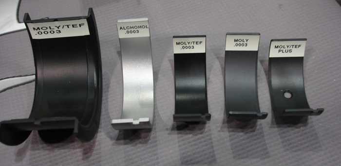
Polymer coated bearings (bi-metal or tri-metal) can also provide an extra layer of protection. Polymer coatings with ingredients such as graphite, molybdenum disulfide and/or Teflon provide lubricity when an oil film is not present. The coating prevents dry starts when an engine has been sitting for a period of time, and it reduces the risk of seizure (at least temporarily) if the engine loses oil pressure while it is running. The added thickness of the coating also provides conformability and embeddability. That’s why most bearing suppliers now offer polymer coated bearings as an option for those who want the extra protection. A polymer coating adds some cost to a set of bearings, but it also adds an extra margin of safety against bearing problems and failures.
Bearing Failures
One thing to keep in mind about bearing failures is that a LOT of things can cause it besides choosing the wrong bearings for the application. The number one cause of most bearing failures is contamination, even in high performance engines.
Lack of cleanliness can kill a high performance engine just as quickly as a machining or assembly error. Metal shot blast, honing residue, grinding debris or metal chips lurking in oil passageways or nooks and crannies of a casting can be deadly to a set of bearings regardless of the brand or type. No coating can protect a set of bearings if a big chunk of metal, silicon carbide, CBN or diamond ends up between a bearing and its journal. Any debris that ends up in the oil will likely end up in the bearings.
Most oil filters will trap debris larger than about 20 microns in size, and a certain percentage of the smaller particles. Synthetic non-woven fiber oil filters will typically eliminate up to 40 percent of the 3 to 5 micron sized particles as the oil flows through the filter. But even that may not be good enough to protect the bearings in a race environment. The extreme loading that takes place inside a race engine during full throttle acceleration can smash the oil film between the bearings and crank journals down to as little as half a micron! That leaves an oil film only a couple of molecules thick to prevent metal-to-metal contact – and almost no clearance for any debris that may have gotten past the oil filter.
Bearing Design Differences
Besides the differences in construction and alloys of high performance bearimgs, there may be additional design changes to improve load carrying capacity such as chamfered oil holes and narrower, but deeper oil grooves or only partial grooves (1/2 to 3/4 of the circumference rather than a full groove all the way around) so the load can be spread across a wider surface. The upper rod bearings and lower main bearings experience the greatest loads, so different oil grooving may be used on the upper and lower bearing halves.
Eccentricity is another factor that can vary depending on the application. Eccentricity is the thickness of the bearing as viewed from the side, with the center typically being somewhat thicker than the area near each parting line. The amount of eccentricity for a stock passenger car engine may be .0002˝ to .0008˝ compared to .0006˝ to .0012˝ for a performance bearing. A typical “H” series racing bearing will have medium eccentricity to control the formation of the oil wedge between the bearing and crank whereas a “P” series bearing will have more eccentricity so it can maintain the oil film at higher RPMs. Stock bearings require less eccentricity because they are operating at lower RPMs.
Many racing cranks have a larger fillet radius at the sides of the journals to improve strength. This requires bearings that are chamfered on the sides to clear the larger radius.
Quality Control
Quality control at every step in the manufacturing, machining and assembly process is so important. Bearing manufacturers go to great lengths to assure bearings are made to the correct size. Many performance bearings are bored rather than broached because boring produces more consistent sizes.
Manufacturers also try to match bearing shell thicknesses as closely as possible (to within .0001˝ according to some manufacturers). Yet, it’s not unusual to find brand new bearings in the box that are mismarked or the wrong size for the application they are supposed to fit. It doesn’t happen very often, but when it does it can create a real disaster if somebody doesn’t catch the mistake.
The same goes for machining crankshaft journals, main bores and rod bores. If the finished dimensions are not correct, you can’t expect the bearings to fit properly. The bearings may be too tight or too loose in the bores. That’s why rod and main bearing clearances should always be measured with a dial bore gauge, not a simple plastic gauge check.
The clearance is the difference between the inside diameter of the assembled bearings in the connecting rod and main bores minus the outside diameter of the crankshaft rod and main journals.
Insufficient clearance may cause a bearing to bind or seize when the engine is assembled, or it may not receive adequate lubrication if a thick racing oil is used in the engine. Too much oil clearance can cause a dangerous drop in oil pressure, noise and a hammering effect that can pound the bearings to death.
Bearing crush is also important. Some performance bearings are engineered with a little extra crush height so they don’t loosen up. For a stock application, the amount of crush should be .001˝ to .002˝, while that for a performance application should be .002˝ to .004˝. Crush helps hold the bearings in the bores and promotes good heat transfer and cooling. If a bearing is too loose, it may overheat or spin.
If you are building an engine with aluminum rods, keep in mind that aluminum expands more than steel when it gets hot. Consequently, the bearings may not fit as tightly in the rod bore when the engine gets hot. What’s more, over time aluminum rod bores can sometimes tighten up. This happens because the serrated teeth on the mating surfaces of the rod and cap wear into each other, reducing the diameter of the rod bore. Because of this, rod bore diameter, bearing crush fit and bearing oil clearances should all be rechecked after aluminum rods have run for a period of time to see if anything has changed. Any type of rod (steel or aluminum) may also have a fitment issue if the bore is out-of-round or elongated.
Bearing Oil Clearances
One size certainly doesn’t fit all when it comes to bearing oil clearances. Old school engine builders usually prefer to build an engine “loose” and run a heavier oil such as 20W-50 or straight 50 so the bearings can handle more crank flex under load. This works well in drag racing because the crankshaft experiences a lot of twisting and flexing. A little extra clearance is also good in a dirt track engine because the engine runs in a very dirty environment. Yet NASCAR engines are often built with much tighter bearing clearances (.0015˝ to .002˝) because they are using low viscosity synthetic racing oils.
Most rod and main bearings run best with .0007˝ to .001˝ of clearance for every inch of crankshaft journal diameter, or .0015˝ to .002˝ inches of oil clearance for a 2-inch diameter shaft – but these numbers will vary with the oil viscosity and application. Typically, an engine builder might add .0005 inches of additional clearance for a performance motor over what he would normally use with a stock build.
One bearing manufacturer recommends the following oil clearances based on the viscosity of the oil used in the engine:
• .002 for 20W and 5W-20 oils
• .0025 inches for 30 and 5W-30 oils
• .0025 to .003 inches for 40W, 10W-40 oils
• .003 to .0035 inches for 50W and 20W-50 racing oils.
As for oil pressure, you only need enough to keep the oil film between the bearings and the journals. The old rule of thumb of having 10 lbs. of oil pressure for every 1,000 RPM is still valid, but some engine builders are going with less to reduce parasitic horsepower losses at the oil pump. An oil pressure reading of 60 PSI at idle may look great on a gauge, but it’s overkill for what most engines need. Most engines don’t need more than about 10 PSI at idle, and can get by with 5 to 7 PSI.
The amount of oil flow will also vary with the application. Aluminum engines tend to run looser and flow more oil than cast iron engines due to the difference in thermal expansion rates. Ditto for aluminum rods. An engine that has piston oilers or supplemental oil feed lines for the rocker arms and valve springs will require more flow and a higher volume oil pump.
Bearings should be installed dry in the bores, then lubricated on the journal surfaces with assembly lube or oil. The engine’s oil system should also be primed before initial start-up to prevent damage caused by a dry start. If you hear any rapping or knocking noises once the engine is running, shut it off. There may be a loose rod cap or excessive bearing clearances that somebody overlooked.


