Posted on Leave a comment

Dispelling Engine Break-In Myths With High Performance Academy


Anyone who has been around high-performance engines knows the term “break-in”. In fact, it’s not uncommon to hear people talk about “break-in periods” for brand new cars, even. What, exactly, is being “broken-in”? What’s the proper procedure? Ask ten people and you are likely to get ten different answers. “This is an area where there is a huge amount of confusion and a huge amount of misinformation,” says Andre Simon of High Performance Academy, an online performance learning outlet.

First things first, what you’re doing when “breaking-in” a new performance engine – or any freshly rebuilt engine, for that matter – should be clearly defined. That is one of the largest pieces of misinformation in and of itself, according to Simon. “We must understand what it is we are actually trying to do. Some people think we are trying to bed in the bearings, or crankshaft, and that’s just not the case,” says Simon. “If you end up with metal-to-metal contact between the bearings and crankshaft journals [which would occur in a bedding process], you’re going to cause damage. Once that contact occurs, no amount of gentile running is going to fix that.”

What is actually being done during engine break-in is fairly simple – it’s the controlled bedding, or wearing-in, of the new piston rings on the hone of the cylinder walls. “We are trying to bed those rings so that they achieve a correct seal against the cylinder walls, and we have a relatively narrow window in which to do this,” relates Simon. “Once we achieve that seal, we end up with an engine that creates good power, has low blow-by, and has low oil consumption.”

“We’re using the rough surface of the hone pattern to abrade the rings and make them seat,” Simon explains. The crosshatch pattern of the hone in the cylinder like a file on the outer surface, creating a perfect fit within the bore. While that may sound simple – and really, the actual mechanics of it are – the process to actually achieve that is a delicate balancing act, as that crosshatch is only abrasive for a limited amount of time. “The reason there’s a narrow window is because that hone pattern will be broken down in time,” Simon continues.

The proper cross-hatch pattern not only retains oil throughout the life of the engine, but the rough finish acts as a file to properly bed the rings in during the break-in process. However the sharp edges only last a limited amount of time. Once those edges are worn down, the ring bedding process is over, whether they’ve properly bedded to the cylinder walls or not.

Where things get complicated, is the proper way to maximize the effectiveness of that period where the crosshatch is essentially file-fitting the piston rings to the bore. “My process is one which I’ve gone though and developed through my career. It works exceptionally well, and as with most engine builders, I’m a bit superstitious about it,” says Simon. “The worst thing you can do while breaking in an engine is baby the engine or allow it to idle for extended periods, particularly when it’s hot. That will place almost no load on the rings and it will allow that hone pattern to be broken down without actually performing its job.”


However, while you don’t want a light load, you also don’t want to go to the other extreme either. “What we want to use is moderate amounts of load and moderate amounts of RPM,” explains Simon. “What happens with moderate loads, is that combustion pressure gets behind those rings, and pushes them out against the fresh hone pattern. That friction against the cylinder wall helps the bedding process along. However, that friction creates a lot of heat, so we need to be careful of that. You don’t want to go straight to wide open throttle and 8,500 rpm.”

Additionally, the lubricant used in the initial break-in period can have a large impact on how well the rings seat., and results in yet another balancing act. “The goal is to use an oil which will allow enough friction for the rings to bed in correctly. Common high-performance synthetic oil is so slippery it will actually inhibit the wear required to bed the rings in. So you don’t want to use super slick full-synthetic oils to break the engine in,” reveals Simon.

He prefers to use mineral-based oil, during break-in, as it will still protect the engine, but not be so super slippery as to be detrimental to the break-in process. There are a number of break-in specific oils on the market, which usually contain other additives to protect other parts of the engine in its early stages of life, and preferences on which one is best are about as varied as the varieties of oil themselves.

One final myth that Simon aims to bust, is extended engine break-in periods. “After a couple hundred kilometers of use, your rings are as bedded in as they’re ever going to be. After that, it’s all downhill, so you might as well get out and start enjoying your engine,” he says. “Exceedingly long break in periods are absolute rubbish.”


Posted on Leave a comment

How to Estimate Your Engine’s Required Fuel Flow

Posted by Jeff Behuniak on Sep 1, 2017 12:49:51 PM

We are occasionally asked, what fuel flow do I need to support my application?  Or, will your fuel filter flow enough for my engine?  These are important questions when selecting fuel filters, lines, and pumps for a performance engine.  You want to be sure that your components can deliverer the fuel needed to supply your thirsty engine.    

Fuel makes power.  Different types of fuel make different amounts of power.  By knowing the amount of power your engine makes or is expected to make and the type of fuel you will be running you can calculate your engine’s required fuel consumption and flow.

Brake-Specific Fuel Consumption

To start the calculations for fuel consumption we use the BSFC (Brake-Specific Fuel Consumption) for the fuel being used.  BSFC measures the amount of fuel needed per horsepower per hour. Fuel is measured in pounds instead of gallons.

download.jpg

Listed below are the BSFC ranges for average efficiency Gas, E85 & Methanol engines at their peak hp output.  An engine’s BSFC can vary depending on load and RPM, these rates aim to represent the peak horsepower environment. The unit of measure here is lbs / hp / hr.

Gasoline   .45  –  .50
E85          .63  –  .70
Methanol   .90 –  1.0

You can used these BSFC values to calculate the fuel requirements for various horsepower levels.  The above BSFC number tell us that our gasoline engine requires .50 lb of fuel per horsepower per hour.  Said another way, we know for each horsepower our gas engine creates we will need .50 lbs of fuel per hour. Expressed as a formula it looks like this:

Given Horsepower  x  .50 lb fuel/hp = lbs of fuel for given horsepower

To calculate Fuel Consumption for a 400 hp Gas engine with a BSFC of .50 lbs/hp/hr:

400 hp x .50 = 200 lbs/hr    

To convert this lbs/hr to a more meaningful gallons per hour we use the conversion rate from lbs to gallons which is 6.2 lbs to 1 gallon of gas

200 lbs/hr  / 6.2 lbs/gal = 32.25 gph

And that’s it!  Now you have an approximate peak gph fuel requirement for your engine that can guide you in choosing your fuel system components.    

If you will be doing this calculation often, you can make it even easier by converting the BSFC you prefer for your fuel from the normal lbs/hp/hr unit of measure to a gal/hp/hr measure.  This way you will only need to multiply your horsepower by that figure to arrive at your GPH rate, without the need for converting from lbs to gallons after.  

BSFC .50 / 6.2  = .0806 gallons / horsepower / hour.

Again we calculate Fuel Consumption for a 400 hp Gas engine.

400 hp x .0806 = 32.24 gph 

Remember, if you are running E85 or Methanol be sure to use those BSFC values in your formula. To calculate peak fuel consumption for a 800 hp E-85 engine we can use a BSFC of .70 and the formulas below. 

800 hp x .70 = 560 lbs/hr          560 lbs/hr /  6.2 lbs/gal = 90.32 gph

OR

BSFC .70 / 6.2 = .113 gallons / horsepower / hour

800  * .113 = 90.40 gph

Note:  These gph flow rates may seem high when compared to your daily driver on the highway, but remember these are not averages, these are flow at loaded peak output.  Regarding the small differences in the numbers between the methods, that is a result in rounding differences.  


What does that GPH rate mean for my Filter?

25-902.jpg

If you are using a quality fuel filter like our CM filters your filter should be out flowing the fittings and fuel lines on your car by a considerable margin. Our filter tests showed that in stock based applications with OE fittings and fuel lines in the 3/8 range the fitting and line size was the determining factor for flow.

Using our 25-902 fuel filter as an example lets see how the filter fitting size and line size relates to flow.  This filter features OEM style Ford fuel fittings specifically found on the 4.6 modular motor Mustangs.  In our testing this filter in isolation flows close to 100 GPH with around 1/2 psi resistance. It can do this because the filtration media is designed for high flow and the point of restriction is limited to the stock style fittings in and out which are short in distance.  Compare that to the long length of stock 3/8 fuel line running to and from the filter.  The long length and twist and turns in the fuel line mean resistance to flow is much greater.  In this application the stock line would not be able to flow much more then 60 GPH without significant pressure flow restriction accumulating.  

When planning your fuel delivery system we recommend first starting with an estimate of the fuel consumption your engine will require. Then determine the line size and pump to support that flow. Next choose a quality fuel filter to match your line size that uses high flow high filtration media like our CM filters.


BSFC is a great tool to quickly examine the relationship between fuel flow and horsepower.  Even though the fuel consumption required at your engine’s peak horsepower will be effected by several variables such as throttle position, RPM, and aspiration type these calculations can get you close.


Posted on Leave a comment

Racing Helmets – Brain Bucket: What You Need To Know

The Sports Car Club of America (SCCA) runs solo events, also known as autocross events, all across the nation. The General Competition Rules (GCR) require a helmet is worn by both the driver and any passenger.

A helmet is one of those things you hope you never actually need. Many refer to this safety device as a “crash helmet” which is something you certainly never want to use it for, however that is exactly what it is designed to be utilized for. These helmets do a very important thing during a collision — protect your brain.


Even if you haven’t attended medical school, we all know enough anatomy to understand we need our brains to live. So, for obvious reasons this is no place to cut corners and try to save a few bucks. The purchase of a helmet can save your life. So, long story short, spend a couple of dollars on your own brain bucket. It is an easy insurance policy.

Not all helmets are created equal, and they are individually designed for different tasks. Automobile racers require a Snell SA certification, SA stands for Special Application.

I often forget what my helmet is really for. I use my helmet as a place to put sponsor stickers and I use it to concentrate before a race. I close my visor, which is the universal sign for “leave me alone for a minute,” and I sit and think about the task at hand. How do I want to start? How am I going to manage my tires? Which cars am I going to draft with, or who am I going to block? My helmet is my Zen place, but that is not the intention of the design. It is designed to save my life when things go sideways, or worse, upside down.

RaceQuip builds high quality yet affordable helmets for auto racing only. They don’t bother building motorcycle helmets. They are strictly in the car racing market.

Certification

When purchasing a helmet there are various options that need to be considered. The first one is the certification. For most car racing enthusiasts you are looking for a Snell SA rating. It is important to understand how helmets are rated as you will see a few different decals on helmets as you are shopping around.

You will see a D.O.T. decal which is really for motorcycle helmets on the public roads. You will see an M rating which is again for motorcycles and you will also see an SA rating. The SA rating also comes with a year associated with it. The year listed on the decal isn’t the year the helmet was manufactured, it is the Snell standards associated with that particular year. You may also run across F.I.A. ratings which come out of Formula 1 and Europe.

This helmet has a Snell SA 2000 rating, which means it is out of date. The ratings are good for approximately 11 to 12 years from the Snell date (depending on new ratings, and a particular sanctioning body’s rules). When you go through tech inspection, this is the sticker the tech inspectors are digging around inside your helmet to find.

So, how in the “snell” did this certification come about? Great question. Pete Snell died in a motor racing accident in 1956 from a rollover collision. Afterwards, a team of doctors, engineers, and scientists got together and, in Snell’s memory, dedicated their work to certifying safety standards in helmets. Since 1957, the Snell Memorial Foundation has been certifying helmets. Why do you care? Because unless your helmet has their certification sticker inside, you ain’t racin’.

This is the drop test at the Snell Memorial Foundation, where engineers spend all day smashing stuff.

To find out how helmets can earn a Snell rating I spoke with Ed Becker, executive director and chief engineer at the Snell Memorial Foundation. The simple answer is helmets are test rated by bashing them into things. One of the tests performed is when a helmet has a 6.1 kilogram metal head placed in it (yes, kilograms because scientists use the metric system), and then the helmet is dropped from 11 feet. Sensors inside the helmet measure the G’s felt by the simulated head. No, they don’t use live humans for this test, for obvious reasons. If the G’s felt are above 243 G’s for a size large helmet, the helmet fails and does not receive a Snell certification.

Ed said helmet manufacturers have their own choice in how they build a helmet, Snell does not mandate a construction process, they only designate the tests the helmet must pass in order to be certified. The goal at Snell is “impact energy management,” which means when the outside of your helmet stops, the inside of the helmet should let your head “ride down” the impact by compressing the inner layer of the helmet, so your brain doesn’t feel the heavy hit.

For the SA 2015 standards, the SA rated helmets are being hit harder than the M rated helmets. Currently, most helmets that arrive at the foundation for testing do pass the tests as the helmet manufacturers engineer the helmets with the Snell standards in mind. However, occasionally helmets do fail, and then they are sent back to the manufacturer for a redesign. Snell rated helmets are safer, because they are tested beyond the government requirements for a basic D.O.T. rating. Those government requirements date back to standards set in 1966 which Ed considers, “Ancient technology.”

Some sanctioning bodies allow you to run an M rated (motorcycle) helmet, however, the recommendation for automobile competition is the SA rating should be used. The motorcycle rated helmets are not designed for impacts with roll cages and are not built with fire-retardant materials. The helmet in this photo, decked out in Girl Power livery, is a Pyrotech SA 2015 rated helmet for auto racing.


Construction/Fitment

Patrick Utt, president of RaceQuip, explained how his helmets are built, “Helmet construction, from inside out, starts with a layer of fire retardant cloth covering a thin layer of soft foam against your head. This covers a 2-inch thick Expanded Polystyrene (EPS) dense foam insert. The EPS liner fits into an outer shell made from one of any various composite materials including fiberglass, Kevlar, and/or carbon fiber. The outer shell has a layer of gelcoat (or clear epoxy) that was sprayed into the mold to ensure the helmet has a good surface finish and releases from the mold more easily. Lastly, a layer of fire retardant paint covers the gelcoat layer.” RaceQuip prides itself for its affordable helmet designs and only builds SA rated helmets.

This helmet cut away shows the construction of an SA rated helmet. There is a lot of engineering in the design of these helmets to ensure you have the best chance possible in a collision.

When deciding which helmet is the right one for you, the best advice I have seen comes from Ken Myers, owner of I/O Port Racing Supplies, who races cars and sells helmets to racers all day long. “If you can go to a store and try the helmet on, you will be much better off versus buying one on the internet and hoping for the best,” he says.

Ken says fitment is the key to being comfortable in the race car. “Size large doesn’t always mean large, and a large helmet in a Pyrotech that fits you doesn’t mean a large helmet in a Bell will fit you the same,” he mentions. “Bell’s higher-end helmets are sized in hat sizes, for example 7 5/8ths. However, just because you wear a 7 5/8ths hat doesn’t mean that same helmet size will fit your head properly. You need to try the different helmets on.”

I/O Port Racing Supplies has many helmet options to choose from. According to owner Ken Myers, it is helpful to take the time to test fit different helmets before making your final decision.

One of the considerations when buying a helmet is the material the shell is made of. More expensive helmets are made of carbon fiber and are lightweight. Ken Myers says there are some advantages to a lighter helmet in a collision. “The more mass on your head in a collision, the more chance for injuries to the neck. Additionally, lighter helmets are easier on the drivers during long stints behind the wheel, like for endurance racers.”

This advice was echoed by Patrick Utt from RaceQuip, “The weight factor is mostly important to racers who spend an hour or more in the car during a race. The lighter weight is less likely to fatigue the neck muscles.”

Ken did offer this warning about lightweight carbon fiber helmets — not all carbon fiber is actual carbon fiber. “Many helmet manufacturers use a mix of fiberglass, Kevlar, and one layer of carbon fiber on the outside of the helmet to make it appear as if it is made completely with carbon fiber, which it isn’t. A $500 carbon fiber helmet, isn’t really a carbon fiber helmet.”

Ken also indicated that just because a helmet is more expensive, it doesn’t mean that it is actually a safer or better helmet, “All SA 2015 helmets have passed the same criteria to meet that Snell standard. A $250 SA 2015 helmet from Pyrotech met the same standards as a $1,300 SA 2015 Bell Carbon helmet. What matters is does the helmet meet your needs?”

There are many different helmets to choose from. The important thing to look at when deciding is comfort and rating for usage (does your helmet fit the rules of the sanctioning body you are racing with?).

Consider Options

Other things to consider when purchasing a helmet are options. Do you want forced air into your helmet? Then you need to purchase a helmet that allows you to pipe in air. Do you race on a dirt track with a lot of dust? You may want a helmet with less air vents in the front. Do you have a radio in your car? You may want to purchase a helmet that has radio speakers already in it.

Sampson Racing Communications can add a radio to any helmet you have, however, some helmets, like this Stilo have radio communications designed into the helmet from the factory.

Shawn Sampson, racer and owner of Sampson Racing Communications (SRC) outfits teams with radio equipment and sells helmets with radio gear already installed. “I love the Stilo helmet line. It’s the helmet I wear when I am racing in the 25 Hours of Thunderhill. You don’t have to worry about ear buds coming out of your ears; the speakers are built right into the helmet. It works great.”

For you guys who get thirsty out on the track you can even modify your helmet to allow for drinking water.

Other things to consider:  if you race at night, you will want a clear face shield. If you race in a sunny place, you may want a dark or smoked shield. If you are an endurance racer and need to drink water during a race, you may need to add driver hydration to your helmet by routing a tube through the front to a camel pack with water.

There are a lot of things to consider when you make your helmet purchase, so it is crucial to think about all of these options before getting out your credit card. For example, if you are going to road race with the National Auto Sport Association (NASA), you are required to have a full-face helmet. Open-face helmets, which are used frequently in autocross events, are not allowed in wheel-to-wheel road racing with NASA. Knowledge is power — read your rule book!


Be fast and be safe. Take the time to ensure your helmet is right for you and what you intend to do with it.

All SA 2015 helmets are equipped with anchors for HANS-style head and neck restraint devices, which means it is no longer an issue that has to be decided by the customer, your helmet will come with those anchor positions already. New Snell standard helmets won’t be out until around October of 2020 with an SA 2020 rating which will provide even more advances in driver safety. Make sure the helmet you buy is right for what you need. When your car is rolling upside down at 100 miles an hour, that is no time to think to yourself, “Darn, I should have bought a better helmet.”

Good luck with your helmet shopping experience and keep the shiny side up!

Posted on Leave a comment

Supporting Your Cylinders – Open, Semi-Closed, Or Closed Deck?


You’ve more than likely heard the terms open deck, semi-closed deck (semi-open), and closed deck before. But, do you know how to identify which design your block uses or why an open-deck that works well for a naturally aspirated build won’t likely last very long if it’s boosted or has nitrous? Which design your engine has will play a major role in the maximum peak cylinder pressure your block can handle, which can be simply translated to maximum power.

Peak cylinder pressure is much greater at the top the of the cylinder, where the combustion event happens. This is in addition to any secondary pressure sources the cylinder might be exposed to, such as forced induction, nitrous, and detonation. Naturally, this is the location that most failures happen, the more pressure you introduce into the cylinder, the more likely the cylinder wall is to bubble, crack, or fail entirely.

The video above, posted by time attack team Jager Racing and featuring Outfront Motorsports, presents the advantages of using a closed deck block on their time attack Subaru WRX STI. The video focuses specifically on the EJ25 motor, but the advantages can be generalized.

Open Deck

An open deck Ford EcoBoost 3.5L V6. Notice the lack of any type of structural support around the top of the cylinders (although some open deck designs utilize a support point at the end of each outside cylinder).

An open deck is one of the most common designs found in lower horsepower aluminum blocks. It is the easiest to manufacture and provides the overall best cooling efficiency, due to the coolants ability to make full contact with the surface area of the upper portion of the cylinder. Some will argue that this block has the benefit of weighing less than its two siblings because less material is used, but this weight difference is marginal for most blocks.

The downside to an open deck is that it provides the least amount of structural support at the top of the cylinder walls, where they need it most. This reason alone makes an open deck block the least reliable choice for almost any type of forced induction or nitrous application, and should be left to low compression, naturally aspirated engines and low boost platforms.

Semi-Closed Deck

A semi-closed deck flat-four EJ25, found in the Subaru WRX STI. Notice the bridges used to help prevent any distortion around the top of the cylinders.

A semi-closed deck is the most common design found in modern factory turbocharged aluminum blocks, and is stronger than an open deck by adding structural support to the top of the cylinders at four points. Using modern casting techniques, this design can handle respectable boost levels into the mid 30 PSI range and a much higher peak cylinder pressure than an open deck (depending on the application).

Because of the added material around the cylinder walls, this style is more difficult to manufacture and requires more machine work before the cylinders can be installed. Some will argue that the added support joints of a semi-closed deck reduces cooling efficiency and is more prone to cylinder hot spots by limiting the surface area for the coolant to contact. At higher horsepower levels, a semi-closed deck is still prone to failure at the points in between the supporting joints, especially in endurance racing or road racing applications where sustained high temperatures are common.

The most common solution for semi-closed and open deck blocks is installing aftermarket sleeves that can support higher cylinder temps and pressure. This process is pretty expensive, but it is highly recommended that you find a reputable machine shop that has experience with your platform. Sleeving requires a lot of precise machine work to not damage the block, so only the best in your area should be trusted.

Left: A factory 3.5-liter EcoBoost engine prior to being machined for aftermarket sleeves. Right: A sleeved 3.5-liter EcoBoost engine.

Closed Deck

A modified closed deck flat-four EJ25, found in the Subaru WRX STI. Notice the lack of any open space around the water jackets (only coolant ports), providing full support around the top of the cylinder walls.

A closed deck design is generally left to iron blocks and aluminum racing engines. It is the perfect design for fully built, high compression, high revving race engines that require the highest level of structural support available. Common on high level drag race motors, this design is also able to withstand prolonged periods of high heat and cylinder pressure commonly seen in endurance racing and road racing.

A closed deck block is much more expensive and requires an entirely different casting procedure if done from the manufacturer, but can also be modified using pieces that are press fit into position around the water jackets. The latter process requires a custom head gasket, along with precise calculations and machine work to verify that the pieces fit properly and that the water ports are drilled properly to provide adequate flow to efficiently cool the heads.

Many will also note that a closed deck block provides the least amount of cooling capability out of the three. Although this is true to an extent, many of todays closed deck blocks have been put through extensive testing and are designed to guarantee efficient cooling.

Conclusion

Depending on the goals for your build, you may need to sleeve your block or upgrade to a closed deck design. Most modern semi-closed deck blocks can handle very respectable power levels before needing to be sleeved or upgraded, and open deck blocks can handle just about anything you throw at it in naturally aspirated form. But, if you are building a race engine and want the ultimate reliability out of your block, your best option is a closed deck design or aftermarket sleeves (depending on the application and your budget).

Posted on Leave a comment

Blueprint Series: Measuring and Setting Bearing Clearances

If we had to choose one operation that epitomizes the process of engine blueprinting – we can’t think of a better one than setting bearing clearance. This goes far beyond slapping a set of new bearings in the main saddles, torquing the main caps in place, and hoping the crank turns over. Blueprinting clearance means establishing a clearance that is your target number and working the components until this number is achieved. Anything else is just bolting an engine together.

We won’t get into establishing specific clearance goals here because that has been previously covered by EngineLabs. We can offer the standard advice that is tried and true – multiply the crank journal diameter by 0.001-inch. As an example with a small-block Chevy main journal of 2.200-inch – then an oil clearance of 0.0022-inch would be a great place to start.

This discussion will focus on main and rod bearings in a mild, street-driven performance engine that might see occasional high-RPM use, like at the drag strip. Perhaps the first bit of information worth mentioning is that this is the total clearance around the circumference of the bearing. So in the case of a 2.500-inch main bearing with a vertical clearance of 0.0025-inch, this establishes there is only 0.00125-inch clearance between the crank journal and the main bearing at the top and bottom. Under maximum load, the oil is squeezed into a very tiny area of clearance measured with five digits to the right of the decimal point–perhaps as tight as 0.00025-inch. The remainder of the clearance is found on the unloaded side–the top side of the main bearing or the bottom side of a rod bearing.

In order to do this job properly, you will need some accurate measuring tools. A minimum of a 2-to-3-inch inside micrometer and a dial bore gauge are necessary. Be sure the micrometers and dial bore gauges will measure down to 0.0001 inch. Cheaper tools often only measure down to 0.001 inch. This is not precise enough by a factor of 10. You will also need a torque wrench and sockets.

The large amount of bearing clearance on the opposite side of the load is used to feed oil between the journal and the bearing, which is why producing sufficient clearance is so important. It is this dynamic loading of the bearings that reinforces why attention to detail is so important. There are other considerations such as bearing crush, eccentricity, and bearing materials that demand close scrutiny, but we will focus on how a DIY builder can create professional results by using high-quality measuring tools and working carefully.

We will make some very important assumptions that the block and crankshaft have either been machined or carefully measured to ensure they are straight, with minimal taper, so that our measurements will pay off with a happy engine when assembled.

Creating the desired bearing clearance starts with accurately measuring the journal diameter. In this case, we’re measuring a big-block crank main journal. The only accurate way is to use a micrometer that measures down to 0.0001-inch.

The first order of business is to measure the crankshaft. We will need a quality outside micrometer, a notebook to record the readings, and a clear, clean work bench. The crank should be clean and ready for assembly. Assuming we’re working with a V8 engine, it’s important to measure the main journals in two locations and record both. If you are really fastidious, it’s a great idea to measure for taper across the journal as well.

Once a journal diameter is established, there are two ways to go about setting up your dial indicator to measure the inside diameter of the bearing housing.

With the micrometer at a specific journal diameter, use this to zero the dial bore gauge (left). We placed our mic in a bench vise to hold it firmly, protected by a thick rag. Setting the dial bore to zero requires attention-to-detail to make sure the zero is accurate. If you induce an error at this stage, every other measurement will be in error. Next, use the dial bore gauge to measure the inside diameter of the housing bore, in this case, the number two main journal that has been torqued (right). For maximum accuracy, measure bearing clearance only in the vertical. Also check for taper in the rod. We had a poorly resized used rod that had 0.0015-inch taper. This is caused when the rods are not switched on the mandrel and only honed from one side. This creates a taper or bell-mouth in the rod big end. So always check for taper on rebuilt rods.

One way is to set the outside micrometer to a specific journal diameter. Let’s use a 454ci big-block Chevy as an example. With a 0.010-inch-under crankshaft, we measured the number three journal at 2.7387-inch. This is exactly 0.010-inch undersize. We can set the dial bore gauge to read zero at this point and then install and measure the inside diameter of the bearings in the number three main.

The second procedure saves time but could introduce a math error. This process measures all the journals. Then the builder sets the dial bore gauge to one journal size and performs the math to adjust the clearance from the dial bore gauge for the different housing bore diameters. As an example, if we set the dial bore gauge to the 2.7387-inch diameter of journal three, then we would add or subtract the difference of varying sizes of the journals to produce the actual bearing clearance. If the journal is larger than our standard by 0.0002-inch, then we would subtract 0.0002 from the dial bore gauge reading for clearance for that main bearing.

We made a simple oil pump adapter for this big-block and mounted it using the stud and nut we planned to use in the engine. We measured clearance before and after torquing this in place and discovered the clearance increased in this situation by .0008-inch!

As an example, if we installed 0.010-under bearings and measured the clearances and all was right with the world, the dial bore gauge should read +0.0025-inch (our desired clearance) for all five main journals. But this only happens on TV car shows and magazine engine articles. In a big-block that we recently assembled for a friend, the crank main journals measured as follows:

Main Journal

Journal Diameter

Actual Undersize

1

2.7393

0.0094

2

2.7390

0.0097

3

2.7387

0.0100

4

2.7384

0.0103

5

2.7383

0.0104

None of the crank main journals measured the same and only number three was the technically correct 0.010-inch undersize. Budget and time limitations prevented us from grinding this crank 0.020-under. Instead, we had to deal with this and use multiple size bearing shells to bring the clearances as close as possible.

Let’s first address the clearances for the 0.010-under number three. Measuring the actual clearance using 0.010-under Federal-Mogul bearings, we came up with 0.0027-inch. This was slightly more than our ideal 0.0025 spec but acceptable. The other four created either too much or too little clearance using just 0.010-under bearings.

Most race bearing manufacturers will offer bearings in +/- sizes. For example, Federal Mogul offers main and rod bearings in 0.001-inch under and oversize versions within the lineup of  standard, 0.010-inch, 0.020-inch undersized bearings. That allows you to set the clearance by adjusting, even with half-shells.

Some performance bearing companies like Federal-Mogul offer optional bearing sizes such as 0.001 undersize or oversize inserts that make it much easier to set an ideal clearance. In our case, we needed 0.011-inch undersized on some of the journals and 0.009-inch-undersized bearings for the front two. Federal-Mogul offers these and saved our bacon. This allowed us to increase or decrease the clearances to get closer to our ideal. While mixing half-shells is acceptable practice, never mix shells with more than 0.001-inch spread and always stay within the same manufacturer. In other words, never mix a 0.009 bearing shell with an 0.011-inch version.

One down side to performing all these customized clearances is that we were faced with purchasing two (and in our case, three) sets of main bearings for one engine. So do all measuring before you buy the bearings. The same is true with rod bearings.

It is accepted practice, for example, to mix one 0.010-under shell with an 0.011-under bearing half on a specific rod or main journal to achieve the desired clearance. Never mix bearings of different manufacturers and never mix bearing halves that are more than 0.001-inch different in size.

The best way to fix this would have been to have the engine align honed to establish the proper housing bore diameter. In our case, the engine had to go back together due to deadlines beyond our control so we did the best we could. The final 0.0035-inch clearance is well within factory tolerances, but it is also 0.0005 inch wider than we would prefer. For a mild street motor, this was acceptable. Another reason this will work is that as the thrust bearing, this additional clearance will provide more than enough oil to properly lube the bearing’s thrust surfaces.

These are Federal-Mogul 0.010-under rod bearings. Note the stamp “L” or “U” on these shells along the upper stamping. The “L” means this shell must be installed in the lower half of the connecting rod so that the bearing’s chamfer will be on the same side as the crank radius. The “U” obviously is the upper insert. If the bearings are inverted, the chamfer will not be adjacent to the crank journal radius and the bearing may rub. This isn’t a major issue, but certainly something to watch carefully.

It’s also important to point out that housing bore diameter, whether it be the rods or mains, have a big effect on bearing clearance. Incorrect clearances are commonly blamed on the bearings when the reality is the housing bores are improperly sized. When combined with inconsistent crank journal diameters, this tolerance stack-up is the real culprit in nearly all clearance issues. Measuring these parts is the only way to know for sure.

At some point in the Blueprinting series, we will also look at the accuracy of the measurement tools you are using. If your measuring devices are not accurate to at least 0.0002-inch, the actual numbers may not be an accurate reflection of what is really there.

When bearings are installed in the connecting rod, always use some type of rod vise to clamp across the cap parting line. This prevents damage to the rod when the bolts are tightened. If you don’t have a rod vise, use a bench vise with aluminum inserts in the jaws to prevent damage to the connecting rod.

It’s also important to point out that bearing clearance will dictate engine oil viscosity. We will have to over-generalize here, but tighter clearances demand thinner oil while wider clearances will need a higher viscosity oil to establish the proper oil-film thickness to prevent abnormal wear.

Most of the details in this story relate to employing common sense and accurate measurement techniques. Accomplish both of those tasks and your engine will live a long and powerful life.

If you really want to get down into the tiniest of details, you can test bearing thickness variations. You will need a round bearing adapter for your micrometer as shown (we found ours through Grainger). However, our experience is that accuracy of measurement becomes more of an issue than variations in bearing thickness. In other words, can you accurately measure to 0.0002-inch?

Posted on Leave a comment

Harmonic Damper: A Key Source for Lost Horsepower

Harmonic Damper: A Key Source for Lost Horsepower

We are all guilty of installing a flashy part on our hot rod or engine that doesn’t add any power, but we’re convinced the system “runs better” with it installed. Now imagine installing a part that doesn’t directly build power, but its interaction with the engine’s rotating assembly can release power that may have otherwise been wasted energy in the form of vibration, or maybe the part just reduces premature wear on bearings and associated components. This part–the harmonic damper–already exists on every street-driven engine, and is often overlooked as just a mounting point for accessory pulleys or a location for attaching weights for externally balanced engines. The harmonic damper presents a crucial opportunity to optimize your rotating assembly to insure longer life or to free up wasted energy that could be better applied to the tires.

So is it a balancer, or is it a damper? The two terms are used interchangeably, but technically they have different functions. A balancer adds weight to help (externally) balance the lower rotating assembly of an engine, while a damper, quells the vibrations during crankshaft vibration which occur as a function of the combustion process. Keep in mind, while all harmonic balancers are dampers, all dampers are not balancers. Yet for purposes of bench racing, both terms are often used to mean the same part.

Romac elastomeric damper with laser engraved timing marks.

                                      
                                       Keeping It Basic

During the combustion process, each piston is forced to move down the cylinder as a result of an explosion contained within the combustion chamber. This stroke imparts a sudden rotational force to the crankshaft. Even though it is a very stout component, a crankshaft is not perfectly rigid. So during these combustion events, the crank will twist slightly in response to each explosion/impact.

This crank twist is analogous to a simple torsion bar with a lever arm at one end. Now assume you hit that lever arm with a hammer. You can imagine there will be some slight twist when you first hit the lever arm, but that would be followed by the arm springing back into place, maybe even vibrating for a short time before coming to rest.

Animation of a crankshaft with 108.476 Hz of harmonic distortion.

In this example, we have torsional twist followed by torsional vibration (during the spring back event). Torsional twist is a function of part length (inline engines will have a longer crankshaft than V-configurations) and thickness, material shear modulus (think: material stiffness), and Torque (force from combustion x crank throw). Similarly, torsional vibration is a function of part length, torsional stiffness, and polar moment of inertia (think: object’s ability to resist torsion). For a detailed explanation of these phenomena, review Himmelstein’s Technical Memo #8150.

What’s the problem?

Torsional vibration has side effects that are rarely desirable. Because force is transmitted into a crankshaft at discrete points in its rotation (example: every 90 degrees of rotation in a V8 application), the output torque is not continuous, thus creating pulses and torsional vibrations. In the event that these pulses occur around the resonance frequency of a crankshaft, the effects can be multiplied. When this occurs, risk of component failure (broken crank) increases as well as the chance of premature wear of bearings. In some cases those vibrations can be transmitted to other points in the powertrain such as the valvetrain (via timing chain) or down the driveline towards the tires. Either direction isn’t desirable as it can rob power in addition to potentially killing parts.


Technology Options

While a few methods to damping have been invented, the vast majority of automotive OEM and aftermarket companies point towards two solutions for controlling detrimental torsional vibration; elastomeric and viscous damping.

The method for elastomeric harmonic damper construction tends to make them the most cost-effective as an OEM replacement or upgrade. Romac Performance Products specializes in elastomeric harmonic dampers and builds products for mild to full race applications. Construction is rather simple, and consists of four parts: a hub, elastomeric band, outer inertia ring, and snap ring. The hub is constructed to fit over the front of the crankshaft snout with a keyway. The hub will usually have a bolt pattern built into the front face which allows for attachment of accessory pulleys. The backside of the hub may have a cavity built for attaching weights to externally balance the rotating assembly. Applied around the hub is the elastomeric band which is constructed of a rubber polymer. Polymer durometer (hardness) gives Romac the ability to add or subtract damping ability, tune for engine frequency, and long term durability.

Fit to the outside diameter of the elastomer band is the outer inertia ring. This outer inertia ring functions as a small flywheel that wants to remain at constant speed despite the acceleration and deceleration pulses that the crankshaft is experiencing. The elastomeric band between the hub and outer ring allows the outer ring to move slightly independently (or at a more constant speed), while the inner hub runs slightly faster and slower in response to torque pulses. A snap ring is inserted inside of the outer inertia ring in order to keep the band and inertia ring in their respective places.

During operation, the band transmits only part of the vibrational forces from the hub to outer ring, while also converting some of that vibrational energy to heat which is dumped to atmosphere. Romac takes great pride in the fact that all of their harmonic dampers are hand assembled, giving technicians that ability to inspect each assembly for best results.

Romac elastomeric 5.8-liter Ford Mustang GT500 Damper with 15-percent supercharger overdrive pulley built-in. The elastomeric material rides between the silver center hub and the black outer ring.

A good example of viscous harmonic dampers are those offered by Fluidampr. Speaking with Brian Lebarron at Fluidampr, he describes a viscous harmonic damper as “contain[ing] a free rotating inner inertia ring that shears through a thin layer of proprietary silicone. As it shears, destructive vibration is transformed to heat. Heat then radiates through the outer housing to atmosphere.” More simply; the viscous damper includes an outer housing, an inner inertia ring (think free-rotating ring inside the housing), and the housing is filled with a THICK silicone fluid which fills in the gaps between the housing and ring.

Click to expand.

Under constant smooth torque applications, the housing and ring spin together. When torque pulses are introduced, the ring wants to continue spinning at a constant speed while the housing is in a constant state of acceleration and deceleration.

The housing and ring speed differences apply a shear force against the silicone fluid between them. The silicone absorbs that shear force in the form of heat which is dumped to atmosphere.

From an OEM perspective, an elastomeric damper covers the vast majority of engines being produced today. The primary reason for this choice is cost of manufacturing as the elastomeric option tends to be constructed of parts which have lower tolerances as well as utilizing raw materials which are more common and don’t demand a premium price. Viscous dampers are often utilized by OEMs in high performance and luxury applications.


Do I Really Need One?

For those familiar with sprint car engines, they know that most sprint competitors don’t utilize a damper at all. Similarly, a minority of drag racers have opted out of a damper with the theory that less rotating mass allows the engine to increase RPM quicker. We’ll keep this discussion at a high level and just point out that sprint and drag engines aren’t intended to see many miles. Careful component selection can help mitigate some overall vibration and ultimate component failures, but the benefits of a damper are undeniable for anybody looking for more than a few quarter-mile passes or a Saturday night main.

Here we can see how the Fluidampr viscous damper changes the large peaks and valleys of vibration the engine sees with an OEM rubber damper.

Selecting a Damper

Consider the following topics when choosing your next damper:

  • Application
    • Daily Driver to Full Race?
      • If a Daily Driver, will stock replacement suffice? Consideration should be given regarding avoiding the previous failure mode.
      • If Performance or Full Race, what type of driving or racing (sprint/endurance)? What types of RPM will the engine see?
    • Function over fashion
      • Always prioritize function. After all, what good is fashion if the chosen damper leads to engine failure? After functional needs are met, feel free to throw all the chrome plating and anodizing as is appropriate.
      • Does the engine need crank pulleys or external balance weights? Will the crank pulleys be attached to the damper body or should they be an integral part of the harmonic damper?
    • Diameter
      • This topic may fall under both Application and Function, but make sure to choose a diameter that meets both functional needs AND will actually fit within the space allotted.
    • SFI or not?
      • If any type of racing or performance is under consideration, an SFI-approved harmonic damper should be a requirement. Many sanctioning bodies will require an SFI 18.1-approved damper. If not, consider what it would be like if a 6-8 pound metal disc came off the front of the engine at high RPM…yeah, don’t skimp here. To understand more about what it takes to comply with SFI 18.1 guidelines refer to SFI -Crankshaft Hub Harmonic Dampers.
    • Budget
      • If you’re rebuilding a daily driver’s engine, that $89 damper from the parts store may be all you need. But if any added performance is your goal, expect to pay according to your intended RPM and speed ranges. That $89 harmonic damper likely will not provide much protection if you’re spinning your engine to 7,000-plus rpm, or hanging a big supercharger on it and doubling or tripling its output. The old saying of “you get what you pay for” is definitely in effect when it comes to harmonic dampers.

In Conclusion

There is a wide variety of choices on the market when it comes to harmonic dampers; from elastomeric to fluid-based, and each one has its place. The ultimate selection is up to you, and your engine will thank you for taking its health into account during the build process.

Posted on Leave a comment

How To Choose The Right Turbo

You don’t need us to tell you that turbochargers are hot. The word on the street is as enticing as it is simplistic. Just stick a turbo on it and you’ll make ridiculous horsepower. We once asked the guru of engine power, Kenny Duttweiler, “How much power can we make with a turbo on a 6.0-liter LS?” His answer was succinct: “How much do you want to make?” That meant that four digit power numbers are achievable. However, in the vein of full disclosure, this won’t be an easy, bolt-on, walk in the park process. If you are motivated, it’s well worth the effort.

We latched on to the learned souls at Garrett Honeywell, who can trace their turbocharger lineage all the way back to 1936; it’s quite obvious they know a little bit about turbochargers. Our story starts with someone who had already taken a stab at adding a turbo to a 6.0-liter LS engine for a street car. Several years ago, Justin Nall decided that a single turbo pushing air into a used, iron 6.0L truck engine seemed like a good idea.

His machine is a choice, Lemonwood yellow ’66 Chevelle with a 4L80E automatic, a decent PTC converter with 3,400 stall, and a 12-bolt rearend filled with a 3.31:1 ring-and-pinion. The car is not particularly light at 3,850 pounds. The engine sports 364 cubic-inches, with a Comp camshaft measuring  .598-inch of lift on the intake and .591-inch of lift on the exhaust, with 234 and 230 degrees of duration at 0.050-inch, respectively. Other components include: Wiseco 10.4:1 pistons, a set of CNC-ported production 243 heads, an Edelbrock Pro Flo intake, and a stock truck throttle body. Overall, the combination is fairly mild. Nall lives in Minnesota, so he puts plenty of miles on his hot rod during the summer months.

Justin Nall’s ’66 Chevelle is a regular competitor on autocross courses, as well as spending lots of time on the street. He was looking for an upgrade for his current turbo, so we plugged some numbers in to choose a little bigger turbo.

At the Summer Nationals event at the state fairgrounds in nearby St. Paul, he also has run the car on the chassis dyno. His initial turbo package was intended as a conservative choice to dip his toes in the turbo waters. Lately he’s decided to up the game with more horsepower, so we thought this would be an excellent way to blaze a trail toward a more aggressive turbocharger. The Chevelle was previously capable of over 650 rwhp, and his goal was to push this to 900 flywheel horsepower; that puts wheel power around 800 to the rear tires. His fuel of choice is E85, because it offers roughly 105 octane, and the engine really loves how the fuel cools the hot compressed air exiting the turbo.

We accessed Garrett’s website, and discovered a wealth of technical information that is divided into areas depending upon your technical level of understanding. If you are just getting into this, then the Basic area will deliver important foundation work for you to understand the concepts. The website also offers intermediate and advanced areas as well, so you can jump right into the area where you are most comfortable.

If you don’t want to run through the math, Garrett also offers its Boost Adviser, which makes the selection process a bit easier. But it’s still a good idea to read this story, because along the way we will explain what all the terms mean and how they are used to help choose a turbo. Many of the details we will discuss here are based on knowing your way around a compressor map. If you’re not familiar with what this is, it’s important to do a little homework by reading all about this on Garrett’s website. But we’ll hit the highlights for you here.

This is the engine in Nall’s Chevelle. It is a basic 6.0L iron truck block engine with a mild Comp roller, 10:1 compression, a set of ported 243 LS1 heads, and an Edelbrock Pro-Flow intake.

The Important Terminology

A compressor map is a basic X-Y coordinate graph, yet it offers a tremendous amount of important information. The horizontal (X) axis of the map is expressed in airflow in pounds per minute (lbs/min). This is the amount of mass airflow the turbocharger can move. Obviously, the larger the compressor housing of the turbo, the more air it can move. There’s a simple trick that everyone uses when reading the airflow portion of this map. The pounds per minute of air increases moving left to right. If you multiply the lbs/min number x 10, that will roughly represent the amount of horsepower that airflow can deliver. So for our goal of 900 hp, this would be represented by 90 lbs/min of air.

The vertical (Y) scale is expressed as a pressure ratio. This isn’t just that number times sea level air pressure (14.7 psia), but it’s very close. One way to explain this is the pressure ratio is derived as the pressure expressed on your boost gauge divided by the ambient air pressure. If we saw 44.1 psig on our boost gauge and this occurred at sea level with an ambient air pressure of 14.7 psia then dividing 44.1 by 14.7 would equal a pressure ratio of 3.0.

Note that we expressed the above ambient air pressure as 14.7:1 psia. The “a” in psia means absolute pressure. The “g” in psig means pressure as read on a gauge. A typical boost gauge represents ambient air pressure as 0, which is why we have to label the pressure we are talking about. In absolute terms, 44.1 psig is 58.8 psia in absolute pressure (14.7 + 44.1 = 58.8). This will become important once we start wading through the formulas. But don’t worry – it’s not that difficult.

So for Justin Nall’s Chevelle, we’re looking to size a turbo with Garrett that will deliver around 900 flywheel hp. To determine how much airflow we will need, Garrett recommends starting by calculating the actual mass airflow. This will reinforce what we just did with the short-cut but it’s worth running through the numbers.

Nall has tested his Chevelle on the chassis dyno several times. A previous combination with a smaller turbo has made 650 hp at the rear wheels, and he is looking for more power from a new turbo—so with Garrett’s help, we ran the numbers…

Air Flow Required

The initial mass airflow calculation uses several variables that we need to know. The first is our estimated horsepower, which is 900. Then it asks for the projected air-fuel ratio and the brake specific fuel consumption (BSFC) number. The BSFC number represents the pounds of fuel consumed per horsepower per hour (lbs/hp/hr). A good, late model naturally-aspirated engine on gasoline will use around 0.45 lbs/hp/hr of fuel. As the number becomes smaller, that means the engine is more efficient and uses less fuel to make the same amount of power.

Because Nall is using E85, which is 85-percent ethanol, this fuel has a lower specific heat content which means we must burn more fuel to make the same amount of power compared to gasoline. So for E85, the BSFC number we will use is a 0.60 number. This means we’re using roughly one-third more fuel to make the same horsepower. This sounds terrible—and it is, if we were in a fuel economy race. But since Nall is focused on making horsepower, this isn’t all that bad. Plus, with a turbocharger, we must add additional fuel to make sure the engine does not experience a lean air/fuel ratio that could damage parts. So add all that up and a BSFC number of 0.60 will work for this application. If we were planning on using a high-octane gasoline, a BSFC of 0.55 would be better.

This calculated number is what we will use to reference mass airflow on the compressor map. Since we’re only using one turbocharger, our goal will require a rather large compressor to move all this air. If we were going with a twin-turbo package, then this number would be divided by two.

AirFlow Requirement (Wa):

This is a typical compressor map. In this case, it is for the Garrett GTX4508. We will use this map to show the mass airflow rate across the X (or horizontal) axis of the map. These values are mass airflow expressed in pounds of air per minute (lbs/min). The Y (or vertical) axis is the pressure ratio, which is essentially the discharge boost pressure divided by ambient air pressure. As you will learn in our story, this value is P2c divided by P1c. In our case, follow 108 lbs/min to where it intersects with roughly a pressure ratio of 3:1. You will see that this falls in the 78 percent efficiency range, which is pretty good.

Manifold Pressure Required

Now that we have our lbs/min airflow requirement, we can move to Garrett’s next step, which is to calculate the Manifold Absolute Pressure requirement. This is possibly the most complex part of this entire selection process, so we’ll take it nice and easy here. The variables we will need to put into the equation include the displacement in cubic inches (364ci), the maximum engine speed in RPM (6,500), the engine’s volumetric efficiency (VE) that we’ll discuss in a moment, and the intake manifold inlet air temperature in degrees Fahrenheit (150°F).

The proposed inlet air temperature is high, since we’re going to calculate this assuming we’re not running an intercooler. Big power numbers with high boost often demand an intercooler, but to keep things simple, we’re going to assume that the E85 will help cool the incoming air, so we’re going with the 150°F number. If we lowered this inlet air temperature, this would lower the calculated boost pressure required, so in a way, we are being conservative.

Garrett also supplies useful graphs like this one that shows the turbine or hot side airflow of two different A/R ratio turbine housings. The red line shows an 84 trim turbo with a 1.01 A/R housing compared to the same 84mm trim with a 1.15 A/R. The larger 1.15 shows increased airflow capacity but would tend to spool slower than the smaller A/R housing.

Volumetric Efficiency (VE) also demands some explanation. This is a number that we will use to determine the capture ratio of the air flowing through the engine. Because of mechanical inefficiencies, a basic street engine is not going to be 100-percent efficient in using all the air that flows past the throttle body. We’re going to put the VE number at 88-percent – which means we’re not going to capture that last 12-percent of air.

As an example, if we have a cylinder that was completely filled, it could capture 10 lbs/min of air, but the reality is it will only be able to retain 8.8 lbs/min. This has a direct bearing on how much power we can make, so a smaller number will be more conservative, while a larger number decreases the amount of air we need to make the same power.

The temperature required for the calculation will use Kelvin, which is absolute temperature, so to convert from degrees Kelvin to degrees Fahrenheit, we have to add 150 to the Kelvin standard of 460. Plus we are also going to use a gas constant (which is 639.6) to make the equation work. Don’t ask why this is important – that’s another story entirely.

This is Garrett’s GTX4294 or very similar GTX4202R turbocharger. It is sized slightly smaller than in mass airflow than our calculated numbers but would be a good choice for an initial buildup of a stout 6.0L engine for the street. Options also include sizing the turbine housing which affects how quickly the turbo will spool up to make boost.

The manifold pressure required will be represented by the abbreviation MAPreq and the equation looks like this:

The result is expressed as absolute pressure (psia). Justin Nall lives in Minnesota, where we found an average atmospheric pressure number for his area of 28.92 inches of mercury which equates to 14.46 psia. Standard sea level pressure (for comparison) is 29.92 inches of mercury. So if we take our calculated 40.48 psia and subtract the ambient air pressure of 14.46, this will give us 26 psig—or the reading we will see on the boost gauge. This would be the theoretical maximum boost required to make 900 hp.

Compressor Discharge

This next step is to calculate the amount of pressure loss that the system will experience between the discharge side of the compressor and the intake manifold inlet. If we were using an intercooler, we would need to know how much pressure would be lost pushing the boosted air through the cooler. But since we are assuming no intercooler here, we can use a basic 1 psi loss of pressure between the compressor outlet and the intake manifold inlet. It’s called P2c because it’s the pressure of the outlet.

The formula looks like this:

P2C Compressor Discharge

  • P2c= MAPreq + pressure loss between turbo and intake manifold
  • Compressor Discharge Pressure Drop = MAPreq + Delta P loss

Assuming a 1 psi loss:

  • P2c = 40.48 + 1 psi
  • P2c = 41.48 psia

It might be helpful to compare this compressor map of the GTX4202 to the previous GTX4508 map. You can see how the larger 4508 version will move more air but will likely be slightly less responsive at lower engine speeds due to its size.

Compressor Inlet Pressure

Engineers who design turbochargers have to account for all pressure loses which also includes the amount of pressure loss we might experience between the inlet air filter and plumbing that is used on the inlet side of the turbocharger. For this discussion we will assume a 1 psi loss or drop between the ambient air pressure and the actual compressor inlet. Because it’s the first pressure on the inlet side, Garrett calls it “P1c.”

The formula is below:

P1c Compressor Inlet Pressure

  • P1c = Ambient Pressure minus (–) Loss Due to Inlet Restriction
  • P1c = 14.46 – 1 psi = 13.46 psia

Calculate Pressure Ratio

If you remember earlier in this story, we looked at compressor maps and how the vertical scale is expressed in Pressure Ratio. That’s what we will calculate next. This is actually fairly simple because all we’re doing is dividing the discharge pressure by the inlet air pressure. This will be the pressure ratio that we will plug into our compressor map.

The formula looks like this:

Calculate Pressure Ratio

  • P2c / P1c
  • 41.48 / 13.46 = 3.08 Pressure Ratio

We now have all the data required to plug into a typical compressor map. Unlike the classic pirate movie where X marks the spot of where to dig for the treasure, there are literally several compressor maps that would appear to work with the numbers that we’ve generated.

The main inputs again are our 108 lbs/min of air required along with a pressure ratio of 3.08. But keep in mind that these are the peak numbers. There are other factors that will have an effect on how the turbocharger operates within the system.
Justin’s experience has shown him that among the more important variables is exhaust backpressure. All turbos generate backpressure and this is especially true with turbos for the street where the exhaust housing is generally sized smaller to help the turbo spool quicker.

This relates to what is called the A/R ratio that relates to the size of the exhaust housing. Larger A/R housings reduce backpressure but also tend to spool slower. According to Garrett, A/R (Area/Radius) describes a geometric characteristic of all compressor and turbine housings. Technically, it is defined as: the inlet (or, for compressor housings, the discharge) cross-sectional area divided by the radius from the turbo centerline to the centroid of that area.

While we estimated inlet air temperature for our turbo selection without an intercooler, you can see in this photo that Nall uses an air-to-air intercooler. As a very rough estimate, you can expect a quality intercooler to experience roughly a 10-percent pressure drop, which means at a 20 psi inlet pressure at the intercooler you might see a loss of pressure to 18 psi. This is a generic estimate and is affected by a number of variables.

After we produced our numbers, we searched through quite a few turbochargers and selected a turbo that we thought would work – a GTX4508. We shared our numbers with the Garrett engineers and they matched a GTX4294R and a GTX4202R to our application. The engineers said the numbers place the turbo selection somewhere between these three turbos. Garrett’s selection is a more conservative choice than our estimate for the Chevelle and much of this could be considered a compromise between ultimate power and decent manners on the street. Garrett’s recommendation is based on much more direct experience and therefore carries significantly more weight.

The 4202R employs a 76mm inducer and a 102 mm exducer sizes while the larger GTX4508R is sized up with an 80mm inducer and 106mm exducer. The larger wheel means it will spin up slightly slower.

In comparing the GTX4202R to the GTX4508, the more aggressive 4508 moves more air, which moves the chart more to the right. This will make more peak power but likely will not come up on boost as quickly, all else being the same. We don’t have the space here to get into how altering the turbine section might be able to help that, but this also means likely changes in backpressure as well.

In Conclusion

As you can surmise, there’s more than a bit of effort involved with choosing a turbo and there are many other variables that we have not discussed. Hopefully this exercise in turbo matching has helped take some of the mystery out of homing in on the right turbocharger. You might want to run through more than one scenario just to get comfortable with the numbers. Have fun with it and see how changing the numbers has an effect on these boost devices. You can also use the Garrett Boost Adviser program to generate the calculations so you don’t have to slog through all the math. Boost Adviser will ask a few questions and then provide some turbocharger matches based on your input. You can also take the calculations and compare points on the compressor maps to find the selection that suits your application.

All this may appear intimidating at first, but as you work with it and as you learn more about how turbochargers work, more of it will make sense. All these calculations are intended to remove the black magic from choosing a turbocharger.

Posted on Leave a comment

Friction Science: Choosing The Right Clutch

Let’s create a scenario that could cause any car enthusiast to break out in a cold sweat. You are sitting in your ride at a crowded intersection and your foot is firmly holding the clutch pedal to the floor. When the light turns green, you plan to annihilate the rear tires on your car. You know your car can do it, you’ve got enough horsepower to immediately turn your tires into asphalt crayons. When the light does turn green, you slide your left foot off of the clutch pedal and smash the throttle. But for some reason, something doesn’t seem right. You see smoke billowing from under your car, but the smell is different. It doesn’t smell like tire smoke. At that moment, you see a guy taking video of you smoking your car’s stock clutch instead of the tires. You, my friend, are about to go viral on YouTube as an epic fail.

959-Burned-Clutch-Pressure-Plate (1)

You have smoked your clutch and the pressure plate looks bad. We’re here to help.

While the OE clutch in your car worked great when your car was all OE, upgrades tend to put more stress on parts — some of us learn that the hard way, but I digress. Replacing the clutch with another OE unit will probably heed the same results, so it’s time to step up. But, stepping up requires a little knowledge about choosing the right parts.

How do you know what you need if you don’t know what’s available? That’s where we come in. We spoke with clutch professionals from Spec, Mantic, and Quarter Master, to get some insight into different clutch materials and designs, and to find out how you can properly choose the system that is perfect for your car.

Clutch Terms You Should Know

When researching a clutch, it is always helpful to know the definition of some of the most commonly used terms in the clutch industry.

  • Friction disc — Made of varying types of friction materials that come into contact with both the flywheel and the pressure plate to create the force required to turn the transmission.
  • Floater Discs — Used in multi-disc clutches, they act as an intermediate surface between the friction discs.
  • Flywheel — This is the steel wheel that connects the clutch to the engine. The pressure plate bolts to the flywheel.
  • Bellhousing — Connects the engine to the transmission and houses the clutch assembly.
  • Pressure Plate — uses spring pressure to squeeze the clutch disc against the flywheel and transmit power through the assembly.

When it comes to deciding on a clutch, there are many options available that will technically fit behind your engine, but do you know what parts are the right choice for your application?

Jeff Neal at Quarter Master told us, “The right clutch choice depends on the usage the clutch will see. Our Pro Series is robust, and has a high-torque capacity which is great for road racing.” He continued with, “Our V-Drive clutch is great for those on a tight budget, and is great for short track, road, and rally racing. Then we have our Optimum series clutches, which are designed for high horsepower racing applications.”

When we asked Geoff Gerko of Mantic Clutch, he recommended their organic disc clutch for daily driver cars that see only occasional passes down the dragstrip. If looking for a clutch that is at home on the street or the race track, Geoff says, “Our Sprung Hub, Cushioned Ceremetalic clutch features smooth operation, great drivability, and increased torque capacity containment. This is our most versatile and popular clutch material for the average enthusiast.” Geoff continued, “Our Solid Hub Ceremetalic also features smooth operation, but is best suited for use in purpose-built cars that see frequent track days or consistent bracket racing.”

Last but not least, Shelly Norton of Spec Clutch told us, “Generally speaking, all of our units are built to survive abuse when used within their specified torque ratings. Most of our “staged” clutches are also classified as multipurpose.” Shelly continues, “Our Stage I through Stage III kits are considered street-friendly, but can still be used for many types of racing. Our Stage IV is good for road racing, drag racing, and drifting; and our Stage V is primarily a drag race unit.”


Friction Materials

feature-4a

Friction materials come in many forms. Choosing the right material can either make or break your driving experience.

As the performance of your car increases, so should the characteristics and durability of the material used to make your clutch disc. The following is a brief synopsis of clutch materials available, and when each should be employed. When it comes to a clutch material for racing, Neal says, “We typically recommend a sintered-metallic (bronze) material. This has a very high coefficient of friction with manageable driving characteristics. For street-performance clutches, we offer organic (rag type) materials for a more street-friendly driving experience that delivers race-type friction capability.”

Organically Speaking

Organic material is primarily used to make stock-style clutch discs. Organic material is acceptable for normal driving conditions and usage, but as operating temperatures rise, or you place the clutch under heavy loads (which is usually accompanied by slippage), the clamping ability will fade because the coefficient of friction drops off. In addition, at high RPM and/or when the disc gets hot, they tend to fail structurally.

Bullet Proof

$(KGrHqR,!jgE5HCzcoLOBOYu!ILw4w--60_57

Kevlar material does make a clutch “grab,” and may not be the perfect choice for a daily driver.

The use of Kevlar material offers a much higher coefficient of friction than organic material, but with some loss in drivability (i.e. it gets grabby when releasing the pedal). This occurs, because, as the coefficient of friction goes up in the disc material, so will the aggressiveness of the material when the clutch is engaged. This usually results in clutch “chatter.” Since Kevlar is compatible with stock flywheels and pressure plates, it makes a good upgrade choice, but using it takes some getting used to in regards to driveability.

Aggressive Grabber

Bronze-metallic materials are the most aggressive materials in regards to clutch friction. Since it is very aggressive, it offers an extended life over Kevlar and organic materials. According to Gerko, “Our Ceremetalic material is our friction material of choice. It engages smoothly, wears well, tolerates the heat, and has a consistent coefficient of friction. This enables us to create clutch kits that accomplish everything for our customers.”

2313_1

Using a bronze-metallic clutch disc will cause the pressure plate and flywheel to wear much faster than organic materials.

By reducing static pedal pressures, usage of metallic materials can result in a quick and clean clutch engagement. Since metallic materials are the most aggressive materials available, it will also wear the flywheel and pressure plate surfaces much faster. Therefore, they should only be used with a steel or nodular-iron pressure plate and flywheel. If used on the street, this material will cause chatter when the clutch is being engaged.

Iron Age

Sintered iron is an optimal choice for street use, as it has a greater ability to withstand slippage and not lose its friction coefficient. Sintered iron is also preferable for high-horsepower applications and drag racing. When it comes to choosing the clutch material for your car, Norton explains, “We actually have particular materials for particular setups. For instance, we do not have one, two, or even three preferred materials. However, our Stage II-Plus carbon/Kevlar hybrid materials and our Stage III-Plus materials are the most recommended in high-horsepower environments. Likewise, our organic and pure Kevlar materials are the most recommended for mild-power applications.”


Checking On Twins

Not only do you have to choose what material your clutch disc is comprised of, but you also need to decide if you need one, two, or more discs. Clutches are generally rated by their torque-holding capacity. A single-disc clutch will inherently have less holding capacity than a twin disc when based solely on their surface area. According to Norton, “We recommend installing a multi-disc unit when using a single-disc clutch is insufficient. If the clutch works but experiences significantly-reduced wear life, it is insufficient. There are also cases where a single-disc might seem sufficient, but the overall setup can benefit from a smaller-diameter, multi-disc unit to deliver better shifting capabilities or a lower inertia flywheel package for significant rate of RPM and horsepower gains.”

A multi-disc clutch will inherently have more holding capacity than a single-disc clutch based solely on their surface areas.

Twin-disc clutches are designed to have a lower inertia, but will have higher torque-holding capabilities since they spread the load across more surface area. Twin-disc clutches also tend to be noisier in comparison to their single-disc counterparts. This is because there are more plates and separator discs in the package. Gerko tells us, “The main goal of a multi-disc clutch is to increase clutch surface area without substantially increasing pedal effort.”

A good rule of thumb is that a single-disc clutch is a good all-around performance clutch to use with a stock or mildly-modified engine. Depending on the clutch material used, it will have OE-like engagement and shifting qualities. Twin discs are designed to handle a lot more torque than a stock or aftermarket single disc, and therefore are a better fit in higher horsepower applications. To make the right choice, you will need to know the torque capability of your engine, and consult the clutch manufacturer.


Weighted Rotation

When talking clutches, you have to factor in the flywheel. The flywheel not only has the teeth for starter engagement, it is also an energy-storing device. A heavy flywheel causes the engine’s RPM to climb at a slower rate than a lighter (aluminum) flywheel, but since it also stores more energy because of its mass, the engine’s RPM will not drop as dramatically (like between shifts) as if using an aluminum flywheel.

A few things to remember: A steel flywheel is heavier and will help the engine retain RPM when shifting. An aluminum flywheel is lighter, and when used, the engine will not have as much rotating mass and will lose RPM much faster when shifting,

Also, a lighter flywheel will allow the engine to spin quicker, but a more dramatic drop in RPM will be noticed (like between shifts), and the lighter weight could also cause an issue if using your car for daily transportation. This is because the lower inertial mass of the lighter flywheel means the car will be harder to get moving from a stop sign or traffic light. Aluminum flywheels are generally used in road or drag race applications where the engine is continually kept at a higher RPM.

What Is Moment of Inertia

The moment of inertia (MOI) is the measurement of an object’s resistance to changes in its rate of rotation. MOI is a huge factor when designing clutches. This is because in order to accelerate a vehicle, you first need to overcome the vehicle’s resistance to acceleration — its moment of inertia. Reducing the MOI has the same effect as adding power to the engine. A small change in the diameter of a clutch has a dramatic effect on MOI. For example, an increase in diameter from 7.75 inches to 11 inches, equates to approximately doubling the MOI. This difference requires almost doubling the power required to accelerate this clutch.

Under Pressure

The pressure plate of your clutch system is what applies the clamping force that squeezes the clutch disc against the flywheel. But just like with the flywheel and clutch disc, you have a choice to make. For this article, we’ll focus on the three main types of pressure plates: the long style, the Borg and Beck, and the diaphragm. According to Gerko, “The diaphragm-spring clutch really is a superior design, because the clutch can be designed to steadily increase its clamping load as the disc(s) wear. This is tremendously beneficial in multi-disc applications. It helps the customer get the maximum performance from the clutch before it needs replaced.”

The long-style pressure plate is identified by the three thin fingers that contact the throw out bearing. The long-style pressure plate is typically used in drag race applications, and will deliver a considerably-hard pedal feel. The Borg and Beck style is similar to the long style in that it functions via three fingers, but the difference is it has wider fingers that release plate pressure. According to Neal, “The long-style design is great for high-horsepower applications like drag racing.”

Clutch-7The Borg and Beck style uses rollers under the pressure plate cover. These rollers are forced outward under centrifugal force as the engine spins. This increases the clamping pressure as the engine RPM increases. Finally, a diaphragm pressure plate uses a series of “fingers” (also called a Belleville spring), that completely encompass the center opening of the pressure plate. The main advantage to this style pressure plate is that holding the clutch pedal down at a stoplight is much easier than with a long or Borg and Beck-type pressure plate. “We almost always prefer a diaphragm unit.” says Norton, “Diaphragm clutch technology is superior for the majority of uses. Diaphragm units produce more clamp load, more of the time, with friendly pedal requirements and high RPM capability. Diaphragm pressure plates are also a no-maintenance option.”

The Choice Is Yours

So which flywheel, pressure plate, and clutch material do you think you need now that you’ve smoked your clutch and become a YouTube favorite?

0809phr_01_z+clutch_play+clutch

At this point, we have hopefully shed some light on choosing the correct clutch. Now that you have done your homework, know your vehicle, and know the professionals you can trust, all that is left is for you to get the right clutch for your ride.

Posted on Leave a comment

Performance Engine Break-In the Right Way


High oil consumption, excessive smoke through the exhaust, high blow-by, lower than expected power output and increased oil contamination are just some of the possible results of an improper engine break-in or run-in. While production engines in new vehicles are already “broken-in” at the factory, any high-performance “built” engine requires a proper break-in procedure to ensure peak performance, minimal oil consumption and a long life. Even if the best parts are used and the proper machining and assembly was executed, an improper break-in can result in some or all of the negative consequences. While there is no universally agreed upon method for engine break-in, DSPORT and Club DSPORT have effectively used its methods for exceptional results for more than 15 years. Before sharing our process, we will outline the goals, history and challenges associated with performance engine break-in.

By Michael Ferrara // Photos by Joe Singleton


185 QuickTech EngineBreakIn 018 R33GTR 1024x561 - Quick Tech: Performance Engine Break-In the Right Way

The Goal

185 QuickTech EngineBreakIn 011 Hone 350x263 - Quick Tech: Performance Engine Break-In the Right WayWhether you spent $1,500 on your do-it-yourself budget engine build or $50,000 on a record-setting-capable engine, the performance of either is dependent on the engine’s first minutes of life. An improper break-in procedure will affect performance, reliability and longevity. The primary goal of the break-in process is to establish an ideal wear profile between the piston rings and the cylinder wall. When a proper break-in is executed, the ring will be riding on a film of oil on the bearing loading surface of the cylinder wall while the valleys in the cross-hatched surface provide proper oil retention. Neither the ring, nor the cylinder wall can experience too little or too much wear for a proper break-in. The process of trying to establish this proper wear profile is sometimes referred to as setting or seating the rings. An ideal setting or seating between the rings and the cylinder results in minimal leakage past the rings, minimal oil consumption, reduced cylinder wear, reduced ring wear and exceptional heat transfer between the rings and the cylinder wall.

185 QuickTech EngineBreakIn 009 Graph 1024x768 - Quick Tech: Performance Engine Break-In the Right WayYears ago, the common practice was to hone a cylinder with a single grade of abrasive stone based on the type of ring to be used. This left a surface with sharp peaks that provided limited surface contact with the ring creating a challenging “break-in”. Today, high-performance machine shops employ a plateau honing procedure where stages of finer stones or abrasive brush knock down these peaks, establishing a better load-bearing surface during break-in.

The benefits of proper engine break-in affects all four cycles. During the intake stroke, vacuum present in the cylinder pulls a minimal amount of oil into the cylinder past the well-sealed rings. During the compression stroke, a superior ring seal limits the amount of fresh air-fuel charge that makes its way past the rings and into the crankcase. During the power stroke, a properly broken-in engine will not only minimize the amount of combustion pressure forced past the rings, it will also maximize the amount of heat transfer from the rings to the cylinder walls due to a greater contact patch. During the exhaust stroke, proper break-in ensures that little if any of the exhaust products find a way past the rings and into the crankcase.      

185 QuickTech EngineBreakIn 010 Graph 1024x768 - Quick Tech: Performance Engine Break-In the Right Way

The top drawing illustrates some of the peaks and valleys present after a single-stage conventional honing process. The second illustration from top shows a plateau honed surface and the valleys that will hold the lubricating oil in place. When improper break-in occurs, a cylinder wall can become glazed (shiny appearance) with burnt oil and wear particles forced into the valley originally holding oil. Over time, the lack of lubrication wears the cylinder and rings even more as shown in the bottom image.

185 QuickTech EngineBreakIn 012 Hone 1024x768 - Quick Tech: Performance Engine Break-In the Right Way

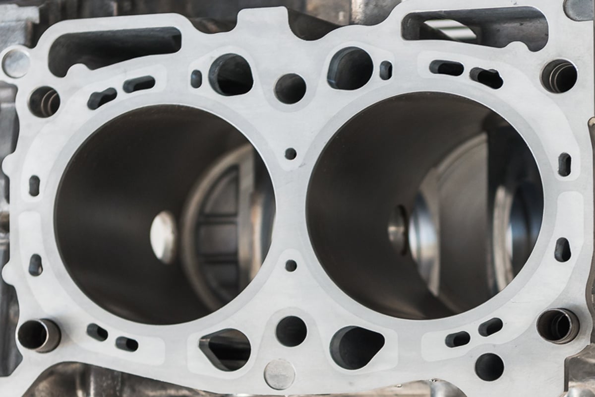
An ideal surface for a cylinder wall would be perfecly flat to maximum contact area while providing a properly-sized resovoir for the oil retention. A plateau honing gets close to this ideal with the Rpk value representing the height of the peaks that will likely be removed during break-in. The Rk value represents the amount of surface that is available to wear away while the RvK value is the measure of the depths of the oil retention valleys

Then and Now

185 QuickTech EngineBreakIn 007 Piston 350x263 - Quick Tech: Performance Engine Break-In the Right WayWhile “high-performance” and racing engines have been built for over 100 years, many of the opinions surrounding engine break-in techniques have not changed with the times. Today, piston ring technology incorporates superior materials and high-tech hard coatings in many instances. As a result, a 1.0mm-thick PVD-coated steel top ring may be selected today over a plain 2.0mm (5/64”) cast-iron top ring that was popular 20 years ago. Different materials, different face profiles and different coatings all influence how the ring will wear. At the same time, the ability to hone cylinders to a superior profile (rounder and with less taper than ever before) and a surface that’s matched across all cylinders in the engine is possible today while it wasn’t achievable years ago. Hence, the full-proof technique used by your uncle or dad’s friend to break in record-setting V8 race engines even built 10 years ago may not be an ideal technique for a state-of-the-art Reference-series engine built at Club DSPORT today.

185 QuickTech EngineBreakIn 008 PistonRings 1024x561 - Quick Tech: Performance Engine Break-In the Right Way

Improved materials and specialized coatings (or treatments) create a hard surface on the face of the rings that accelerate break-in and reduce wear.

Nippon Piston Ring (NPR), Mahle, Riken and Total Seal are the likely manufacturers of the piston rings found on whichever brand of high-performance piston that you’ll find in an engine that uses “mm” instead of “inches” to measure the bore size. All four of these companies are constantly pushing development on higher-strength materials and the application of high-tech coatings or processes useful for piston rings when it comes to the compression and second rings. In addition, these manufacturers are also looking for ways to develop oil rings that provide minimal oil consumption with minimal ring tension (to reduce friction and improve fuel economy). Unfortunately, the ideal surface finish is rarely, if ever, provided to the customer of the new set of pistons and rings. Why? Because less than 1.0-percent of the machine shops in the country have the means to measure or achieve a specific cylinder finish. As a result, they may be delivering engines to customers where some or all of the cylinders are “too rough” or “too smooth” in the most basic terms. In these circumstances, some or all cylinders may fail to properly seat the rings (regardless of the break-in process used). If the machine shop or engine builder that you select doesn’t own a profilometer, doesn’t have the ability to match the surface finish of all of the cylinders and doesn’t have a direct line of communication with the ring manufacturer, you will be rolling the dice as to having an engine that is capable of establishing a proper ring seal.    

JOIN THE CLUB

185 QuickTech EngineBreakIn 013 LeakdownTest 1024x490 - Quick Tech: Performance Engine Break-In the Right Way

At Club DSPORT as soon as the cylinder head is final torqued to the block, a measurement of cylinder leakdown is recorded for each cylinder. This is the baseline starting “cold” value for leakdown. At this time, it is also noted when the leakage is most likely occurring by listening to the intake port, exhaust port and crankcase. As mentioned before, these cylinder leakdown numbers are substantially better when the valve job for the cylinder head is done with a cylinder head torque plate (a.k.a. “hot” plate) in place. When a Club DSPORT hot plate is used, all of the leakage in each cylinder is only audible at the crankcase.   

Evaluating the Quality of Break-In

Just as there are no universally agreed upon methods for engine break-in, there also isn’t any universally agreed upon benchmarks to evaluate the effectiveness or success of a break-in process. Fortunately, we’ve identified some indicators that all properly broken-in engines will share.

First, cylinder leakdown tests of the engine before, during and after the break-in process in both a cold and normal operating temperature state will directly indicate the quality of the seal from the top and second rings. Each and every cylinder should improve during the break-in process until a point where the leakdown stabilized to a final number. If the number goes down initially, but then begins to increase, some part of the break-in procedure being used may not be ideal for the engine undergoing the process.

185 QuickTech EngineBreakIn 014 LeakdownTest 1024x490 - Quick Tech: Performance Engine Break-In the Right Way

If your engine builder didn’t supply the cylinder leakdown figures on your new engine, be sure to record the values before the break-in process.  You will also need to take readings during the break-in process.

Second, the chassis dyno being used for engine break-in can also be used as an indicator. The break-in process should be done with the electronic boost solenoid control bypassed to limit boost pressure to the wastegate spring. This should deliver very consistent boost pressures during the break-in. Without changing any fuel or ignition calibrations to the engine, the engine should show a consistent improvement in power output as the ring seal improves during the break in process. When a point is reached when the power no longer continues to increase, the top and second rings are likely to be nearly or fully seated. A few more passes following the break-in procedure are recommended to ensure a fully seated condition.

Third, when a PCV system is in place, measuring the crankcase pressure may also serve as an indicator to the quality of the break-in and resulting ring seal. If crankcase pressure can be logged during a dyno run, there should be a reduction in pressure as ring seal is improved during the break-in process. Unfortunately, many competition engines have been modified to reduce or eliminate crankcase pressure even under cases of extreme blowby. Hence, this may only be viable for engines with non-modified crankcase ventilation systems.

Fourth, keeping a log of oil consumption may be a great indication of the quality of the break-in procedure, but it will likely be too late to improve the situation at this point in the process. Still, an inspection of the oil at every fill up looking for changes in color and smell can indicate the quality of the ring seal. If the oil in the new engine smells of fuel and turns black quickly, chances are that the break-in process was limited in its success.

185 QuickTech EngineBreakIn 016 CylinderBore 1024x768 - Quick Tech: Performance Engine Break-In the Right Way

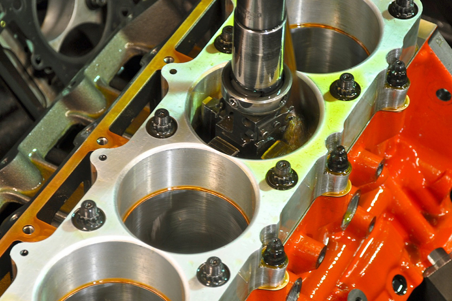
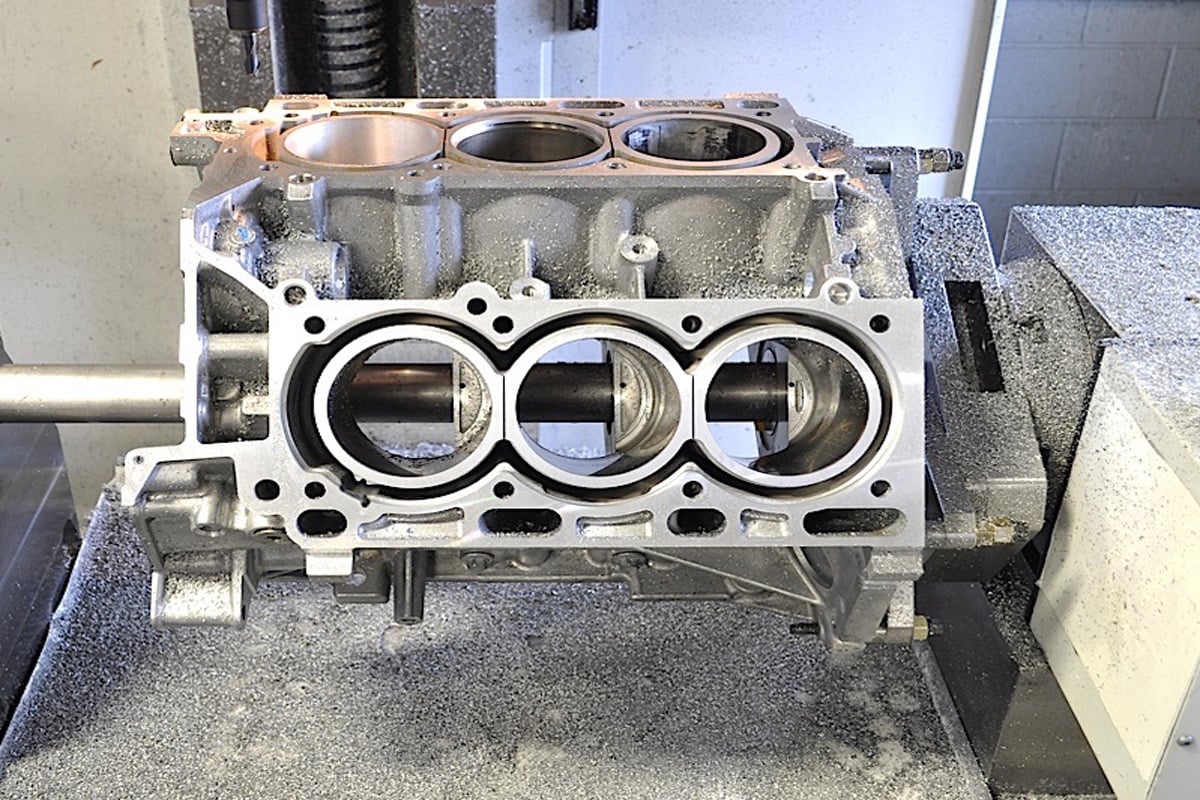
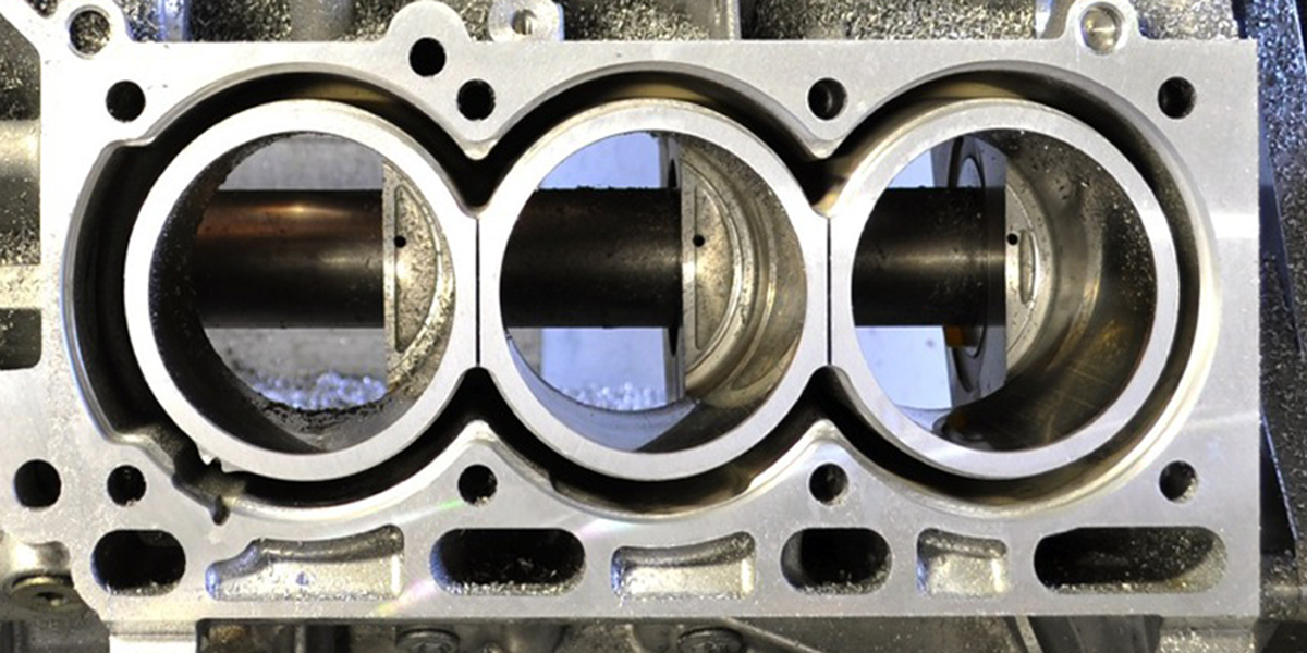
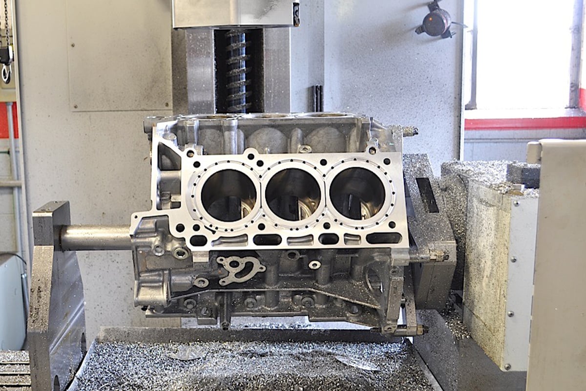
The angle of the crosshatch pattern will determine the speed at which the rings rotate on the piston. This pattern must remain constant from the top to bottom of the cylinder. The cylinder wall of this Club DSPORT big-bore FA20 has the cross-hatch angle, RpK, Rk and RvK values optimized while maintaining a roundness better than 0.0003”.

Finally, inspection of the cylinder bores can often indicate the quality of the break-in procedure. Depending on the engine, a bore scope can sometimes be used to take a look at the cylinder walls. When properly broken-in, the cylinder walls should still show the cross-hatched pattern with an absence of vertical lines or shiny spots n the bore. If the crosshatch pattern is gone and the cylinder bore appears shiny, excessive wear has occurred on the bore and the cylinders should be re-honed and a new set of rings should be installed.

185 QuickTech EngineBreakIn 015 CylinderBore 1024x490 - Quick Tech: Performance Engine Break-In the Right Way

Break-In Pitfalls

So what causes an engine to have an unsuccessful break-in? Two of the most common mistakes involve fuel wash and improper loading of the engine. Fuel wash occurs when an engine is flooded with fuel on initial start-up or before a proper ring seating has occurred. The excess fuel strips the cylinder of the oil film normally present between the pistons rings and cylinder wall. With no oil in place, metal-to-metal contact results in scuffing. Scuffing can also occur if there is an absence of an oil film during the assembly process and the engine is dry started. How can fuel wash be avoided? Since engines running E85 are harder to start and more likely to be flooded, brand-new engines should be started on gasoline whenever possible (OEM actually use a dry fuel like natural gas or propane when new engines are started to avoid any chance of fuel wash). In addition, the fuel injectors should be new or have been serviced to ensure that they are not leaking additional fuel into the cylinders. On engines using lambda feedback, a set of fresh O2 sensors is also advisable.   

185 QuickTech EngineBreakIn 017 MotulOil 1024x561 - Quick Tech: Performance Engine Break-In the Right Way

A quality synthetic oil is definitely the right choice AFTER the engine is broken-in. Use it too early and you may never seat the rings.

Even when fuel wash is avoided, an improper loading of the engine during its first minutes of life can also lead to a failed break-in and seating of the piston rings. If the engine spends too much time getting to normal operating temperature and then is not loaded enough, the rings may not see the temperatures and pressures required to exert the proper amount of force on the cylinder wall. An absence of the proper force will lead to an establishment of small contact patches instead of a complete band of contact across each entire ring and cylinder. The improperly set ring allows combustion pressure to escape past the areas where contact was never established. As a result, many advocate a fast and hard procedure for the loading of a freshly built engine.   

Pre-Start Ritual

The purpose of the pre-start ritual for proper engine break-in is to do everything possible to get the engine fired up as quickly as possible while running a proper air-fuel ratio and reaching normal operating temps in short order. One way to ensure this is to never attempt to break-in an engine at the same time you are trying to calibrate a new engine management system and fuel system setup. Trying to accomplish both at the same time is a recipe for disaster. Instead, it’s best to get the fuel and spark calibration as dialed as possible on the original engine, before the new engine is installed. Alternately, using a complete factory fuel and engine management system on a fresh engine may also have significantly better results than rolling the dice on being able to get a decent calibration completed during the short window of opportunity.

It is also advisable to check the condition of the ignition system and the quality of the spark that is delivered. With the electrical connection to the injectors removed, the ECU can be tricked into firing the coils when the cam angle sensor is rotated. This doesn’t work on all vehicles, but it will on some. Checking that all coils fire and a strong blue spark is delivered when the threaded portion of the spark plug is grounded to the engine means that the ignition system should be capable of lighting off the air-fuel mixture required to get the engine running.

185 QuickTech EngineBreakIn 001 Chart - Quick Tech: Performance Engine Break-In the Right Way

Performing the cold engine cylinder leakdown test will not only establish the baseline condition of the “before” break-in engine, it may also shed the light on a problem that can be addressed before the engine is fired.

Oil selection is critical to proper break-in. A number of manufacturers offer specific blends of mineral oils and additives specifically for “engine break-in.” These oils are highly recommended as both the base oil and the additive package is designed specifically for this purpose. If you do not have access to an engine break-in oil, the next best choice is to select a high-quality non-synthetic oil and combine it with an engine break-in concentrate. Engine break-in concentrates include special anti-wear additives that help to protect parts upon initial break-in. Using an API-graded non-synthetic oil alone may not provide enough anti-wear protection as API graded oils have had most of the anti-wear additives removed over the past years for emissions purposes. Finally, avoid semi-synthetic and full-synthetic oils entirely as break-in oils. These oils will not allow for the required amount of wear and will deliver an improper break-in that is similar to an engine that didn’t see enough load during break-in. Ideally, an engine pre-oiler is used to prime the oiling system so that running oil pressure was reached even before the engine is started. This ensures that there are no components in the engine’s lubrication system that will be run dry at startup. Additionally, priming of the fuel system to establish the running fuel pressure in the fuel rail is also recommended for quick start-up.

185 QuickTech EngineBreakIn 006 Moroso 1024x561 - Quick Tech: Performance Engine Break-In the Right Way

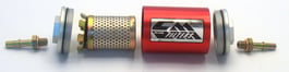
Using an engine pre-oiler or a Moroso Accumulator to feed the engine pressurized oil before being fired up for the first time ensures that the oiling system is primed and ready to go.

While it is often difficult to accomplish, getting the engine’s coolant temperature closer to its running temp will also improve the chances of a quick start-up. When this cannot be accomplished, simply choosing to start the engine at the warmest part of the day will also be advantageous.

Break-In Procedure: Fire Up to Flush

With just some basic conventional motor oil filling the crankcase, the first priority with a fresh engine is to get it fired up and to its normal operating temperature as quickly as possible. Once the engine fires up, it’s best to keep the engine speed varying between 1,500 and 3,500 RPM until the normal engine coolant temperature is reached. Varying of the engine speed will help ensure that a set wear pattern isn’t established before the engine is at normal operating temps. Once the engine reaches normal operating temps, shut the engine off and perform an oil and oil filter change. This flushing procedure removes the bulk of any assembly lubes used on the engine along with contaminants that may have been missed in the cleaning process before assembly of the engine. Fill the engine with break-in oil or conventional oil with a break-in additive at this point.  

185 QuickTech EngineBreakIn 002 Chart - Quick Tech: Performance Engine Break-In the Right Way     

Engine Break In R33 Engine Bay

Break-In Procedure: Dyno Time

Set the rev-limiter between 50-to-60-percent of redline and verify that boost will not exceed the wastegate setting. With its fresh break-in oil and new oil filter in place, the engine is ready to see some load on the dyno as soon as normal operating temperatures are reached again. On the chassis dyno, get the car up to speed and into the gear where it is typically dyno tested. With an inertia-based dyno, start at about 50-percent throttle and let the engine work its way through the RPMs up to just before the rev limiter. Once near the rev limiter, come off the throttle and let the engine coast down remaining in gear back down to your starting RPM for the pull (usually about 2,000-2,500RPM). Repeat this for a total of three-to-five passes at 50-percent throttle. The number of passes will be indicative of the engine’s ability to stay within its normal operating temps. Each pass should take no longer than 2.0-seconds per 1,000RPM covered. If it takes longer, move to a lower gear and repeat the test. Do not engage the clutch or put the transmission in neutral during the run-in time. For brake-type chassis dynos, set the load so that the engine RPM sweep speed is between 1.0- and 2.0-seconds per 1,000 RPM. Once these three passes are completed, coast the vehicle down to idle, apply the dyno brake and shut off the engine. Take a cylinder leakdown reading of the easiest cylinder to access and record the value.

185 QuickTech EngineBreakIn 003 Chart - Quick Tech: Performance Engine Break-In the Right Way

At this point the engine should be allowed to cool down for 15-20 minutes. This cooling down period allows the valves to conform to the valve seats while also providing adequate time for heat to transfer from the piston rings that may only be partially seated to the cylinder walls. Repeat the process and record leakdown. Next, raise the rev limiter to 70-to-80 percent of redline. Again, the engine should be started and brought up to operating temp for the next series of pulls. This time the process is repeated to the higher engine speed at 75-percent throttle. After three to five passes are completed, coast the vehicle down to idle, apply the dyno brake and shut off the engine. Take a cylinder leakdown reading of the easiest cylinder to access and record the value during the 15-20 minute rest period before the next set of pulls.

Now the rev limiter can be set to its actual redline. For the final series of passes, throttle will be at 100-percent too. Set the dyno up to record the horsepower from each of the passes. Make the first full pull to redline and then coast the vehicle down to idle, apply the dyno brake and shut off the engine. Take a cylinder leakdown reading of the easiest cylinder to access and record the value during the 15-to-20 minute rest period before the next pull. At this point, it’s essential to keep the time between pulls as similar as possible. Also, try to get the engine coolant, oil temp and intake air temps as similar as possible. This may require a shorter or longer cool down period between runs. During this process, you will hopefully witness two consistencies. First, the power and torque output of the engine should increase with each pull as the ring seal improves with the proper seating of the piston rings against the cylinder wall. Second, the measured cylinder leakdown should decrease with each successive pull for the same reason. At some point in the process, the engine will stop producing additional power and it will no longer show decreases in the amount of leakage from the cylinders. At this point, the rings and cylinders have made a nearly complete or a fully complete setting. An additional two or three pulls should be made to verify this condition.

185 QuickTech EngineBreakIn 004 DynoChart 1024x609 - Quick Tech: Performance Engine Break-In the Right Way

At this point, the engine oil and oil filter can be changed to the oil that is recommended for normal operation. Since the break-in has been verified as successful and complete, it is OK to switch to a synthetic oil at this point for its superior protection.       

Break-In Procedure: Road Warrior

Ideally, you will be able to break-in your engine on a chassis dyno as described above. However, it’s not realistic to address the many that will choose to break-in a new engine on the street. The most important aspect here is to make sure that you have a vehicle that is roadworthy and safe and to choose a location that will not put you or other drivers in harm’s way. The process for breaking in the engine on the road follows a similar pattern to the chassis dyno loading. However, it may require lower gears as to not exceed safe speeds. In this case, a higher number of passes should be made at each stage. Letting the vehicle cool down for 15-20 minutes between road sessions, is key. While it may not be as easy or practical as in the case of the dyno method, taking cylinder leakdown tests to record the effectiveness of the process is essential. These readings will be the only indicator of the likelihood of success in the break-in process.        

185 QuickTech EngineBreakIn 019 R33GTR 1024x561 - Quick Tech: Performance Engine Break-In the Right Way

Winning Results

More power, more torque, improved engine durability, extended engine life, zero blowby and minimal oil contamination are some of the benefits of a proper break-in session for a new engine. While poor machine work and inferior quality components may dictate a different course of action to achieve a proper break-in, the process, procedures and methods outlined here will have excellent results for most good-to-excellent quality engine builds. By employing dyno results and cylinder leakdown results, the progress and success of the break-in process can be tracked. Using these tools as indicators prevents the process from ending too soon (not achieving the desired result) or being pushed too long (creating more wear than necessary). Since any procedure is open for improvement, we’d love to hear about your experience using the Club DSPORT procedure and the results that you obtain.   


Posted on Leave a comment

Bearing Clearances

Is it better to build an engine with tighter bearing clearances and run it on low viscosity synthetic motor oil, or is it better to build an engine with more traditional or even looser bearing clearances and use heavier viscosity oil?

 
Tight bearing clearances and relatively thin synthetic multi-viscosity motor oils work well in many performance applications from NASCAR and circle track racing to drag racing.

 
Keep in mind, however, that most of these engines are purpose-built engines that are machined with exacting tolerances. Crankshaft journals are precision ground to be as round, flat and true as possible, the journals are micropolished to a mirror-like finish of a couple microinches Ra or less, the bearings are precision fit to exact tolerances using a bore gauge and micrometer (not deformable plastic gauge), and the engines are run on high quality synthetic racing oil, not ordinary motor oil.

 
The oil clearance is the gap between the inside diameter of an installed bearing and the outside diameter of the crankshaft or camshaft journal. The clearance is measured 90 degrees to the bearing parting line, which is the thickest part of the bearing (bearing thickness tapers slightly toward the parting line).

 
Reducing the oil clearance between the rod and main bearings and the crankshaft has a number of advantages. A smaller gap spreads the load over a wider area of the bearing surface and distributes pressure more uniformly across the bearing. That’s good, provided the bearing is strong enough to handle it. A smaller gap also decreases the volume of oil that has to flow into the bearing to maintain the oil film between the bearing and shaft.

 
That’s also good, provided the oil is thin enough (low viscosity) to flow well into the bearing. This also reduces the amount of oil pressure the engine needs, so some extra horsepower is gained by reducing the load on the oil pump.

 
In a NASCAR engine, rules limit the minimum diameters of the rod and main journals on the crankshaft. The rods are 1.850? in diameter while the mains are 1.999?. Most of these engines are running rod and main bearing clearances of .001? or less, and they are doing it with low viscosity racing oils such as 0W5, 0W30 and 0W50. These racing oils are as thin as water and are highly friction modified.

 
They also contain extra anti-wear additives such as ZDDP (phosphorus levels up to 1,850 ppm or higher) to protect the cam lobes and flat tappet lifters. These are race-only oils and are not recommended for street use because they do not contain the same detergents, dispersants and corrosion inhibitors as ordinary motor oils. Ordinary motors have to handle extended oil drain intervals while racing oils do not. Also, the level of ZDDP is too high for late model vehicles equipped with catalytic converters.

With fuel injection, many NASCAR engines are now making close to 900 horsepower without a restrictor plate, and are turning 9,500 rpms for 500 miles. The bearings take quite a pounding but hold up extremely well (when was the last time you heard of a NASCAR engine blowing because of a bearing failure?). But what works great for NASCAR may not work in other forms or racing or on the street.

 
One of the disadvantages of closer bearing clearances is that it can increase both bearing and oil temperatures. That’s no problem as long as the bearings and oil can handle the heat, but if they can’t it increases the risk of lubrication breakdown and bearing failure. That’s why high quality synthetic motor oil is absolutely essential if you are building an engine with tighter than normal clearances.

 
The old rule of thumb is to provide .0007? to .001? of bearing clearance for every inch of shaft diameter in a stock engine. Consequently, if the crankshaft has two-inch diameter journals, the rod and main bearings should be assembled with about .0015? to .002? of clearance.


For performance applications, some bearing manufacturers recommend adding an extra half a thousandth of clearance. Why? Because the rod bores don’t stay round in a performance engine at high rpm. When the piston reaches top dead center on the exhaust stroke, inertia stretches the rod and elongates the bore on the big end of the rod. This, in turn, deforms the bearings and reduces bearing clearances on the lower rod bearing while increasing it on the upper rod bearing.

 
For high revving performance engines, some bearing manufacturers recommend rod bearing clearances of .002? to .003?, with an absolute minimum clearance of no less than .0015?. The tighter the clearances, the tighter the geometry requirements are for the crank journals (as round, straight and smooth as possible with little or no taper).

 
Street engines can benefit from tighter tolerances and thinner oils for everyday driving. But when power adders such as nitrous oxide, turbocharging or supercharging are used, or the engine’s power output gets up in the 450 to 500 plus horsepower range, looser bearing clearances are probably safer to accommodate crankshaft flexing, main bore and rod bore distortion.

 
The same reasoning applies to drag motors, truck pull engines and other performance engines that produce serious horsepower. Many of these engines are built with rod and main bearing clearances in the .0025? to .003? range.

 
For the Saturday night dirt track racer, clearance is your friend because of the contaminants that often get into the crankcase. Looser is usually safer.

 
Rod and main bores should be as round as possible with no more than plus or minus .0005? of variation for a performance engine (.001? is close enough for stock). You also have to take into account the fact that the bearings themselves may not be perfect. Manufacturing tolerances of up to plus or minus .00025? are not unusual in some bearings, while others may vary only .00015? or less.

 
Main bore alignment is also critical. Some bearing manufacturers say adjacent main bores should have no more than .0005 inch of misalignment (.001? overall) if you are using tri-metal bearings, and no more than .002? of misalignment between adjacent bores (.002? overall) with aluminum bi-metal bearings.

 
One of the advantages of looser bearing clearances is that it allows more room for “slop,” which is important if the crankshaft isn’t machined to near perfection or there is some misalignment in the main bores. Wider bearing clearances do require a heavier viscosity oil (such as a 20W50 multi-viscosity oil or a straight 30, 40 or 50 oil). The heavier viscosity oil is absolutely necessary with wider clearances to maintain the oil film between the bearing and shaft so the bearing isn’t starved for lubrication. This also requires more oil pressure from the oil pump and/or more oil volume.

 
The amount of oil that is actually between the bearing and shaft surface at the point of highest load isn’t much. Though the installed gap between the bearing and shaft may be .001? to .0015? or more, the oil is displaced when the bearing is loaded. At its thinnest point, the oil film may only be .00002? thick (1/100th the diameter of a human hair!). That’s not much oil between the metal surfaces, but it doesn’t take much to maintain hydrostatic lubrication. When the shaft starts to turn, an oil wedge forms between the shaft and bearing that lifts the shaft up and away from the bearing surface. The shaft then glides on the oil with minimal friction.

 
If a crankshaft grinder wobbles while a crankshaft is being ground, it can leave lobes around the circumference of the journal. These may be invisible to the naked eye and very difficult to detect with a micrometer. But if there’s any distortion on the surface, it may interfere with the formation of the oil wedge under the shaft if the bearing clearances in the engine are too tight. Polishing the crank can reduce surface roughness on the journal but it won’t get rid of the lobes or ribbing.

 
Another factor to consider is that the upper Babbitt layer on a tri-metal bearing is very thin, typically .0005? to .0008? thick. The top layer of Babbitt acts as a dry film lubricant when there is no oil between the shaft and bearing. That’s fine for a dry start that may only last a couple revolutions of the crankshaft, but it is quickly wiped away if the engine starves for oil when it is running under heavy load or at high rpm.

 
And once the protective upper layer of Babbitt has been destroyed, the intermediate layer of copper/lead alloy will quickly seize if there’s no oil film to keep it separated from the shaft.

 
One of the reasons why many performance engine builders use tri-metal bearings is because they want bearings that have good seizure resistance in high rpm applications. Tri-metal bearings also handle high engine loads well and have good fatigue resistance. The Babbitt surface layer also provides embedability if dirt or debris gets past the oil filter. Tri-metal bearings are typically recommended for use with forged steel crankshafts.

 
Aluminum bi-metal bearings, by comparison, have high wear and corrosion resistance. With harder aluminum/silicon alloys, they can also handle higher loads while providing good anti-seize properties. Aluminum bearings are often recommended for cast iron cranks because they have a polishing effect on the journal surface. What’s more, according to some bearing manufacturers, a high silicon alloy aluminum bi-metal bearing will actually resist seizure longer than a tri-metal bearing if the protective oil film goes away.

 
That brings us back to the oil and bearing clearances. The oil doesn’t care what kind of bearing and shaft it is lubricating. It only needs to maintain enough oil film between the two surfaces to provide hydrodynamic lubrication and prevent metal-to-metal contact. There has to be enough oil pressure and flow to keep the bearings lubricated and cooled, and the oil itself has to have enough shear strength so it isn’t pushed out of the gap between the bearing and shaft at the point where the load is greatest.

 
Multi-viscosity synthetic motor oils flow more easily than conventional straight weight oils at both low and high temperatures. So they can handle cold starts as well as elevated operating temperatures (which is really important with turbochargers). To reduce friction and improve fuel economy, most late model stock engines are factory-filled with 5W20 or even 0W20 oil. Combined with tighter engine assembly tolerances, these oil and bearing combinations work relatively well for everyday driving and even mild performance use. For racing applications, though, the oil needs to be formulated specifically for racing – especially if the engine has a flat tappet cam that requires plenty of ZDDP in the additive package.

 
You can get oil viscosities ranging from 0W5 to 120W60, with 15W40 being a popular viscosity for stock car racing, road racing and spring cars. For wider bearing clearances, some prefer to use a heavier 15W50 or 20W50 oil. In drag racing Top Alcohol and Pro Mod classes, AHDRA Nitro Bikes and blown alcohol tractor pulling, 20W60 may be the lubricant of choice. For NHRA Top Fuel dragsters and Funny Cars, a 70WT oil might be used. So the type of oil that’s used will depend on the application and the bearing clearances inside the motor.

 
An additional layer of protection can be achieved by installing coated bearings. Various types of proprietary coatings are available that provide scuff resistance where there is no oil between the bearing and shaft. Such coatings cost extra, but are good insurance against dry starts and may save a crank if the engine loses oil pressure in a race.

 
Finally, regardless of what type of bearings you put in an engine or how close you set the bearing clearances, always use plenty of assembly lube to coat the bearings. Also, use the proper break-in oil when the engine is run for the first time. Break-in oils are typically a straight 30W oil without friction modifiers for fast ring seating. But they also contain extra ZDDP anti-wear additives to protect the cam and lifters. The break-in oil can then be drained and replaced with the type of oil (conventional or synthetic) that will be used from that point on. Be sure to tell your engine customer how important it is to use a high quality oil and that it has the correct viscosity to match the bearing clearances and lubrication requirements of the engine and application.


reducing the oil     clearance between the rod and main bearings and the     crankshaft has a number of advantages. a smaller gap     spreads the load over a wider area of the bearing     surface and distributes pressure more uniformly across     the bearing.tri-metal bearings     handle high engine loads well and have good fatigue     resistance. aluminum bi-metal bearings, by comparison,     have high wear and corrosion resistance. some engine     builders use coatings for extra protection in case of     contact with the journal, but others say it is not     necessary."if

WhatsApp WhatsApp us