Posted on Leave a comment

Explaining Under- And Oversized Engine Bearings With King Bearings

When the subject of bearings and bearing clearance comes up, there is almost always a misunderstanding that takes place, thanks to the verbiage used in the discussion. So, today, with the help of King Engine Bearings, we’re not only going to clear the air on the terminology of under- and oversize bearings, but also some of the ways you can easily fine-tune your clearances to the half-thousandth of an inch.

Oversized Versus Undersized

The first, and most important item to clear up before we even get started is the terminology we’re going to be using. All engine bearings come in the standard (or STD) sizing for the specific application. That bearing size is designed to fall 100 percent within factory specifications for bearing housing diameter (be they main bearings or rod bearings), crankshaft journal diameter (be it a main journal or rod journal), and factory-specified oil clearance. So, if absolutely everything in your engine is to factory specifications and tolerances, standard bearings are perfect for you.

However, we live in a less-than-perfect world, and a lot of times we’re doing things that would make factory engineers cringe (officially, anyway). To address the variances in sizing and to allow for component wear, alternate-sized bearings exist. These are referred to as undersized or oversized bearings. Now, where the confusion comes in here, is that in both bearing designs, there is more material than standard. Because A) bearings are designed to work at a minimum material thickness, and making them thinner would make them weaker, and B) if your journal is too large, you can simply machine the journal.

Here you can see the various bearing sizes offered by King in their lineup.

That said, oversized bearings do exist in the King lineup. “In an oversized bearing, material is added to the outside, increasing the outside diameter,” explains King Bearings’ Guy Haynie. “Those bearings are used when material has been removed from the engine block or rods.” These bearings, in a standard bore diameter with a standard-sized journal, will reduce the oil clearance by .001 inch (.0005 inch per bearing shell). Conversely, if your main bore or rod’s big end diameter is slightly oversized, they will bring oil clearance to factory specs.

The other option is undersized bearings. “In an undersize bearing, material is added to the inside, decreasing the inside diameter,” explains Haynie. “They are used when material has been removed from the crankshaft journals.” Undersized bearings come in far more size options. Because not only do they come in the same .001-inch variation as the oversized bearings, but also in .010-inch, .020-inch, and .030-inch undersize variations, for journals that have been turned down .010-, .020- or .030-inch, respectively.

To further complicate the issue, within each of those undersize variants an oversize variation (denoted by an X in the size) exists, as well as a variant with .001 inch less clearance. What that means is that, in the King bearing lineup, options exist to go from standard, or to gain an additional .001 inch of (or “loosen up”) oil clearance. On the other side of the equation, the available undersize options are .001, .009, .010, .011, .019, .020, .021, and .030-inch of less clearance, giving you the ability to “tighten up” your clearances.

These .001-inch-undersize LS rod bearings allowed us to mix with standard-size bearing halves to pull out .0005 inch of oil clearance from our rods.

Fine Tuning Those Clearances

As you might have seen recently in LS5.0’s short-block build, we found ourselves in the middle of the clearance range in our rods. We wanted to tighten up our clearances by about .0005 (half a thousandth) of an inch. Looking at the chart, our only option appeared to be reducing the clearance by .001 inch, or twice what we wanted to take out. So, what to do?

That is where mixing bearing shells comes in. By taking a standard rod bearing lower half, and a .001-inch undersized upper half rod bearing shell, and combining them in the same connecting rod bore, our clearance is increased by half a thousandth of an inch. That brings our tolerances exactly where we want them. This is common practice among engine builders who are constantly chasing ten-thousandths of an inch, and don’t typically settle for “good enough.”

This kind of granularity gives you the ability to fine-tune your oil clearances without a trip to the machine shop the alter journal or housing diameters, with the only cost to you being a second set of bearings. A few best practices to follow, are to place the undersized bearing halves in the same positions (either all upper or all lower, not mixing and matching) throughout the engines. The next is that this is a method to get .0005 inch of variation. It’s not recommended to use bigger variances, like trying to get .005 inch of clearance change by using a standard and .010-under bearing half.

By understanding how bearing sizing works, you are not only able to understand your options when assembling your next engine, and potentially avoid another trip to the machine shop if your clearances aren’t exactly where you want them, but this knowledge can also allow you to fine-tune your bearing clearances like a pro.

Here you can see the rod clearances with standard-sized bearings (on the left) and after swapping in half a set of .001-inch undersized bearings. On paper it should have tightened up exactly .0005 inch, but in reality we pulled a few extra tenths here and there.

Posted on Leave a comment

Wastegating 101: How Does A Wastegate Work, And Do You Need One?

It’s wrong to say that a diesel engine absolutely needs a turbocharger, but boy do they help. Naturally aspirated, a 7.0-liter diesel (basically the size of a new pickup engine) might only make a little over 100 horsepower, so it’s clear that boost is much-needed. That’s why virtually all modern diesel engines are turbocharged, so much so that the term turbodiesel is actually recognized as one word.

In the early years (think 1989 Dodge Ram with a Cummins), turbo systems were fairly simple. A turbo was hung off the exhaust manifold and was spun by exhaust pressure in order to feed air into the engine. That was it. No wastegate, no intercooler, no variable geometry–nothin’. As technology progressed, however, all of these things were added, as all of them are beneficial to the turbodiesel engine. One of the very first items that made its way into turbodiesels was the wastegate. But what exactly does a wastegate do?

The most popular wastegate design for turbocharged diesels is the internal wastegate. It’s called this because the wastegate is incorporated into the turbine housing, and is used to bypass the turbine through a small hole right before the downpipe.

The Advantages of Running a Wastegate

Turbochargers spin at a very high rate of speed–up to 100,000 rpm in some cases–in order to windmill air into an engine at pressures that are much higher than atmospheric. A modern OEM turbo may run at 30 psi or more, while competition versions can run upwards of 70, 80, or even 100psi. In the end, though, every turbo has its limit. Over-pressurizing or over-speeding a turbo can result in catastrophic failure and that will ruin a turbo. Possibly even damage the engine.

Simply put, a wastegate bleeds off the exhaust pressure that drives the turbocharger. This in term limits the amount of boost the turbocharger creates, and also the maximum compressor speed. Score one for the turbo that was just saved. There’s more, however, as turbo sizing can also be adjusted, which means a smaller, quicker spooling exhaust side can be fitted for low-rpm response, and then pressure can be bled off up top in the rpm range. This is the main reason that Ram, Ford, and GM all went with wastegate setups; it protected the engine from damage and gave a more usable and extended rpm range.

wastegate

Sled pullers don’t normally run a wastegate because they need every last pound of boost the turbo can create in order to make maximum horsepower. The large safety blankets are installed to prevent shrapnel in case the turbo explodes.

When Don’t You Need A Wastegate?

If there are times that you need a wastegate, surely there are times when the opposite is true, and you don’t need one. Many competition vehicles that aren’t using nitrous oxide injection (we’ll get into that later) will run non-wastegate turbochargers, as they’re looking for literally the most boost pressure the turbo can produce, and are also not too concerned with elevation changes or drivability.

Other applications that run at a fairly specific rpm like tractors or generators can also get away without running a wastegate, mainly for cost reasons. But for the diesel performance industry, wastegates are beneficial.

wastegate

Exploded diagram of a wastegate. Photo courtesy Precision Turbo and Engine

How a Wastegate Works

A wastegate is a fairly simple system. Most mechanical wastegates use a simple diaphragm with a spring inside that opens at a preset pressure. This pressure can be changed anywhere from 5psi to 50psi (or more) depending on the spring setups and boost referencing available. This assembly in turn actuates a valve, that opens towards the atmosphere, venting excess pressure.

This type of wastegate is simple and effective and can be used outside the turbocharger (an external wastegate) or integrated into the turbo (internal wastegate). Variable geometry turbos can also create a wastegate effect through a nozzle or vanes, but since they are complex and computer-controlled, we’ll stick mainly to valved gates.

wastegate

In addition to wastegate springs, boost can be regulated to the top and bottom ports to control when and if the wastegate opens. This way the wastegate can almost be infinitely adjusted, down to 1psi increments.

Wastegate Tuning

At first, this may sound counter-intuitive, after all the wastegate is the control right? Technically, yes that’s correct, but there’s still a lot of “dialing in” that has to occur. A good starter spring for a wastegate is somewhere around a 15-pound spring. This means that once the turbocharger reaches 15psi, a boost line to the bottom of the diaphragm will open the wastegate and relieve some back pressure.

On a diesel, however, you may want a lot more boost, something along the order of 40 to 70 psi for most trucks, so, therefore, regulated air must be run to the top of the diaphragm to keep it shut. Adding a regulated 30-psi to the top of the gate now means that the turbo won’t overcome the spring pressure (and boost on top of it) until about 45 psi. Adding full boost to the top of the gate will effectively keep the wastegate shut; eliminating it completely.

Case Studies

Sometimes it’s best to have a few examples in order to get the hang of how something works. Here we have a couple of street trucks, a drag truck, and a sled-pulling rig all to show how a wastegate is used (or not used) on each setup.

Truck number one is a street truck. It is a 1996 Dodge Ram with minor fueling upgrades and 57mm/71mm ATS compound turbos with a single internal wastegate.

We had the pleasure of tuning this truck on the dyno with pressure monitors everywhere, so we could report how much power it made under various configurations. Before we hit the dyno, we ran it on the street where it only made 57psi with its limited fueling. That seemed low so we pinched off the wastegate line, effectively closing it. Boost hit 65psi, but the truck didn’t feel any faster.

How much back pressure can a diesel create you ask? Well, if the giant flame out of Cole Dow’s race truck is any indication, a lot. Heavy nitrous use is one application where an external wastegate is almost mandatory.

The dyno would tell the story. After our first run, the truck made 400rwhp at 65psi, but with a whopping 99psi of backpressure (or drive pressure) which was far and away from the magical 1:1 boost to drive pressure that most folks aim for. Opening the wastegate saw a drop in boost of 8psi to 57psi, but drive pressure was a mild 64psi, and the truck actually picked up in power to 432rwhp! In this case, proper wastegating netted an increase in power even at a lower boost level, due to an increase in engine efficiency.

Truck number two is a drag truck. It is a 2003 GMC 2500 with heavy fueling upgrades and tuning, a stock turbo with an internal wastegate, and a lot of nitrous.

After this truck ran 6.60s in the eighth mile we had to adjust our glasses, because there was no way it should have been that fast on the factory turbocharger. The racer had initially been running the turbo in the danger zone at nearly 40psi, but he found that by putting a larger diaphragm actuator (Banks Big Head) he could lower the boost to 30psi and just add more nitrous and run even faster! This was a case where the wastegate was being used to just keep the turbocharger alive with nitrous, since adding N2O to the mix dramatically increases drive pressure.

Truck number three is a 1999 Dodge Ram sled puller. This truck features heavy fueling upgrades and a 3.0-inch turbo with no wastegate.

Sled-pulling trucks are great examples of diesels that may be run without a wastegate, even though they make extreme amounts of boost and horsepower. Since these engines operate at an extremely high (4,000 to 6,000rpm) rev range and go down track at a fairly constant rpm (say 4,500 to 5,500rpm) they don’t necessarily need a wastegate.

Instead, the boost is controlled by very large exhaust sides and effective intercooling on the intake side. If the turbo explodes because of excess speed or pressure, a “better turbo” is simply found instead of a wastegate. It’s for this reason the best turbos for pulling can cost $5,000 or more, and while you could drive this type of setup on the street, it would be downright miserable. There have also been claims (mostly on tractors) of 100psi or more from a single turbo, which is downright insane.

The piping for turbo systems can get pretty complex on V-shaped engines, especially when compound or triple turbos are involved. Still, it’s almost always beneficial to run a wastegate.

Truck number four is another street tuck. This 2008 Ford F-250 utilizes heavy fueling upgrades, a Compound Turbo system with a VGT high-pressure turbo, and twin external wastegates.

The turbo setup on 6.4-liter Fords is a factory compound setup that includes a variable geometry high-pressure turbo. So right from the factory, they’re fairly complicated. This particular truck has probably the most extensive wastegate-tuning time on the dyno we’ve ever heard of, and took nearly 100 hours of fuel, timing, and tweaking to dial in.

After some initial runs, the truck made 730rwhp, but the tuner decided there had to be more in the combination because the 82mm turbo made enough air to flow more than 1,000rwhp. So the tweaking began. As the boost began to rise, the backpressure climbed fast, and at a little over 40 psi, the truck had a backpressure reading of more than 80psi. The trend continued until the sensor peaked at 85psi.

True backpressure was over 100psi. So, the decision was made to incorporate two external wastegates (one per bank since it was a V8) and dial it into work with the factory VGT curve. After a bunch of tweaking, the truck arrived at 67psi of boost with 84psi of backpressure, and 908 hp. It was also dead reliable and driveable, although the quick-spooling turbos ate transmissions after a few dynos run with more than 1,800 lb-ft of torque. Again some changes were made and the wastegates and VGT were used to limit power down low to 1,600 lb-ft, and the truck lived a long and happy life.

Posted on Leave a comment

Bearing Clearance and Oil Viscosity Explained

K1 – Blog

Bearing Clearance and Oil Viscosity Explained

The relationship between bearing clearance and oil viscosity is a delicate balance. Read on for more information on how to get it right!There are some fairly famous duos in the entertainment industry – Abbott and Costello, Rogers and Hammerstein, and Batman and Robin among the more illustrious. So it may not be much of a stretch of the imagination for an engine guy to include the pairing of bearing clearances with oil viscosity as a duo you should become acquainted.

The typical rule that most engine builders follow is that bearing clearance establishes the viscosity of the oil to use within a given oil temperature range. Generally, the tighter the bearing clearance, the lower the viscosity the engine can use while wider clearances require thicker oil. But there are plenty of variables that come into play that are worth investigating.

oil viscosity 01

Viscosity is a rating system for oil that rates the oil’s thickness at a given temperature. Production engines are increasingly moving to thinner, less viscous oil in search of improve fuel economy but there are performance advantages to thinner oil if the bearing clearances are somewhat tighter.

The traditional bearing clearance standard for street and most performance applications has been 0.001-inch of clearance for every one inch of crank journal diameter. So a typical small-block Chevy 2.200-inch rod journal would call for a bearing clearance of 0.0022-inch. Some add another 0.0005-inch to be safe – making that 0.0027-inch.This standard works very well especially for engines using production tolerance parts where there could be minor issues with out-of-round or tapered journals or even minor errors in measurement.

This approach isn’t quite as colloquial as it may seem. There are several contributing factors that directly affect a given bearing clearance. The top three variables are load carrying capacity, the amount of oil flow allowed by the clearance, and localized oil temperature. These three are best considered together as opposed to individually since each affects the others in important ways.

oil viscosity 02

The only right way to begin accurately measuring bearing clearances is with a micrometer that can accurately measure to 0.0001-inch. That’s a tenth of a thousandth.

A bearing’s load carrying capacity is directly affected by clearance. As the clearance is tightened, load carrying capacity increases. As a generalized statement, 0.001-inch clearance offers a higher load carrying capacity than 0.002-inch using the standard 2.45-inch small-block main journal size as the example.

Load capacity increases with less clearance because it spreads the load over a wider bearing surface area, which increases the capacity. Think of this like wearing a pair of snow shoes that allow you to walk on deep snow without sinking in. Remove the shoes and your feet sink because your weight is concentrated on a smaller surface area. So as bearing clearance increases, the load carrying capacity is reduced because the load is concentrated in a smaller area.  

Bearing Oil Clearance Chart

Oil Viscosity Rod BearingClearance Main BearingClearance
20w / 5w20 < 0.0021 <0.0020
30w / 5w30 0.0021 – 0.0026 0.0020 – 0.0025
40w / 10w40 0.0026 – 0.0031 0.0025 – 0.0030
50w / 20w50 0.0031 > 0.0030 >

Common sense dictates that bearing clearance directly affects oil flow with predicable results. Reducing the clearance will increase the restriction to flow and reduce the volume of oil past the bearing. Because of this reduced flow, the localized bearing temperature will increase. If this temperature exceeds the oil’s thermal stability limit, the oil will begin to oxidize and break down, reducing its ability to lubricate. We will get into oil viscosity shortly as this plays an integrated part in this scenario.

So bearing clearance becomes a balancing act between these three factors to establish a clearance that satisfies all as efficiently as possible. This is how that 0.001-inch of clearance per one inch of journal diameter was created as the best compromise.

oil viscosity 3

Once the journal diameter is established, use the same micrometer to set a dial bore gauge to the journal size. The clearance read by the dial bore gauge will be the bearing clearance. In this example, we’re looking at 0.0027-inch of main bearing clearance. Clearances must always be checked in the true vertical.

Perhaps this would be a good place to take a slightly closer look at exactly how those running clearances play out. Using simple round numbers, let’s start with a 2.00-inch rod journal with 0.0020-inch of clearance. This assumes we will have 0.001-inch on the top and bottom of the journal, which is true but only in a theoretical sense.

In a running engine, cylinder pressure pushes downward on the piston, reducing that 0.001-inch figure.  A loaded connecting rod at peak cylinder pressure will reduce that oil film clearance to as small as 0.0002-inch. With a static bearing clearance of 0.002-inch that means the upper half of the rod bearing has 0.0198-inch worth of clearance. This is important because this larger clearance creates a space easily filled with fresh oil for the following rotation.

oil viscosity 4

This Driven Racing illustration offers a microscopic view of what happens when operating clearances become tight. The peaks of the crankshaft journal can overlap the peaks of the bearing material causing wear. This is called a mixed film condition and can be caused by either tight clearances or an oil viscosity that is to thin perhaps caused by high oil temperature. 

This leads directly to the value of film thickness, which is created by a combination of the oil viscosity, bearing speed, and load. Oil viscosity predictably changes with temperature while the bearing speed is determined by the combination of the journal diameter and engine rpm and load is of course application dependent. All of these factors play into establishing the thickness of the film of oil. We spoke to Lake Speed, Jr., with Driven Racing Oil who used these three factors (and more) to perform a test of film thickness and stability with different oils and bearings at Shaver Racing Engines in Torrance, California.

oil viscosity 5

This 500 hp iron block LS generated 80-plus psi of oil pressure, so we drained the 10w30 and replaced it with 5w20 viscosity oil. From 4,000 to 6,500 the engine gained an average of 3.1 hp. The engine still produced over 70 psi peak oil pressure with the 5w20 oil so there are further gains to be realized.

His test was aimed mainly at evaluating coated bearings but it also looked at the ability of the oil to maintain its given film thickness under extreme temperature. It is commonly acknowledged that synthetics do a much better job of lubrication and protecting engine components compared to conventional oils at elevated oil temperatures. Speed’s test compared a synthetic Driven oil to a conventional Driven oil of the same viscosity and additive packages. The visual evaluation of the bearings along with a used oil analysis (UOA) revealed radically reduced physical contact between the crankshaft and the main and rod bearings with the synthetic oil. This offers specific evidence that a higher-quality synthetic offers real advantages especially with engines making big power where heat is a factor.

Ironically, Speed’s test employed a mild, 400 hp 383ci small-block Chevy at slow speeds, which can be abusive on bearings because of the extreme load. This is why lugging an engine at low speed isn’t a good idea as the loads increase dramatically. The quality of the oil played a big part in maintaining the proper lubrication barrier between the bearings and the crank journal. According to Speed, “Today’s oils have much greater load-carrying capacity that older oils.” This higher capacity spreads the load over a larger area which improves the overall capacity and avoids stress fractures that can occur in bearings due to excess load. 

All of these factors play into the final decisions around bearing clearance and viscosity.  If all we do is change to an aluminum connecting rod for example, this should require an increase in bearing clearance if for no other reason than because aluminum offers a linear rate of expansion that is roughly twice that of steel or cast iron. This will also have a direct affect on the running clearances. This however, should be carefully considered. As an example, you might think that an all-aluminum engine would demand a much different main bearing clearance compared to an all-iron version.

07

Driven Racing Oil’s Lake Speed, Jr. performed a series of tests of synthetic oil (left) versus conventional oil (right) on engine bearings in a small-block Chevy. Not surprisingly, the synthetic’s more stable oil film dramatically improved bearing wear even over a three-hour, high-load-low-rpm test. Both oils used the same viscosity and additive package so the only difference was the base oil.

Looking at this a little closer, most performance small-block Chevy aluminum blocks feature steel main caps. So now we have an aluminum block with steel main caps and the decision is whether this warrants a change in main bearing clearance. If we consider that all of the load will be applied to the steel main cap side of the engine, decreasing the main bearing clearance to account for the added growth of the aluminum block may not necessarily be a good decision. Tighter clearances also demand very careful cold weather starting and warm-up procedures because aluminum also will contract at twice the rate of iron or steel. Most engine builders we spoke to said they don’t make major clearance changes when building an aluminum block engine.

While bearings need a solid oil film to protect against wear, there are multiple factors that come into play in order to create the ideal combination of load carrying capacity and oil flow while minimizing oil temperature. This demands a careful balance of clearances, oil viscosity, and temperature control to avoid problems. The good news is as oil quality continues to improve, this thermal stability will continue to push toward lighter oil and tighter clearances with potential improvements in both durability and power.

Driven Bearing Clearance vs Oil Viscosity

Main Bearing Clearance Oil Temp Lessthan 160 F Oil Temp160-220F Oil TempOver 220 F
Iron Block      
0.0034-0.0039 10w40 or 15w40 15w50-20w50 20w60 – 60w
0.0028-0.0033  5w30 or 10w30 10w40 or 15w40 15w50-20w50
0.0022-0.0027   0w20 or 5w20  5w30 or 10w30 10w40 or 15w40
0.0016-0.0021         0w10   0w20 or 5w20  5w30 or 10w30
0.0010-0.0015         0w5         0w10   0w20 or 5w20
       
Aluminum Block      
0.0029-0.0034 10w40 or 5w40 15w50 or 20w50 20w60 or 60w
0.0023-0.0028  5w30 or 10w30 10w40 or 15w40 15w50 or 20w50
0.0018-0.0022   0w20 or 5w20 5w30 or 10w30 10w40 or 15w40
0.0012-0.0017       0w10 0w20 or 5w20 5w30 or 10w30
0.0006-0.0011       0w5 0w10 0w20 or 5w20

Connecting Rod Clearance

Clearance Oil Temp Lessthan 160 F Oil Temp160-220F Oil TempOver 220 F
Steel Rod      
0.0028-0.0033 5w30 or 10w30 10w40 or 15w40 15w50 or 20w50
0.0022-0.0027 0w20 or 5w20 5w30 or 10w30 10w40 or 15w40
0.0016-0.0021 0w10 0w20 or 5w20 5w30 or 10w30
0.0010-0.0015 Ow5 0w10 0w20 or 5w20
       
Aluminum Rod      
0.0023-0.0028 5w30 or 10w30 15w50 or 20w50 20w60 or 60w
0.0018-0.0022 0w20 or 5w20 10w40 or 15w40 15w50 or 20w50
0.0012-0.0017 0w10 5w30 or 10w30 10w40 or 15w40

This Driven Racing Oil chart (above)  illustrates some basic starting points for different engine applications. It’s important to choose the correct viscosity grade for the maximum engine oil temperature. As oil temperatures increases, the viscosity will drop. When there is a conflict between rod and main clearances, it’s always best to use the heavier of the two viscosity recommendations.  Keep in mind that these should be considered as recommended starting points for bearing clearances and oil viscosity. Individual applications can certainly vary.

Posted on Leave a comment

Making A 1,500-Plus Horsepower Honda B18 Engine Live


This is the story of opportune meetings, overcoming odds, and unrelenting levels of girl power. It is also the story of an undersized Honda Civic, its equally tiny engine, and the tenacity that it takes to become one of the fastest front-wheel-drive drag racers on the planet.

For Process Development Manager, Nichole Elff, adrenaline has been a core component in her life for as long as memory serves. So when she was introduced to the import scene back in college, her interests pivoted from horseback riding, to customizing cars with friends on the weekends. The following twenty-year import automobile love affair would see Nichole start with a 1994 Acura Integra rocking basic bolt-ons, to what what you see here today: A dedicated XFWD championship Honda race car driver with stacks of wins to her name, including the title of 2nd fastest FWD female driver in history.

All of this has been made possible by a surprisingly small powerplant: A 119ci 4-cylinder B18 Honda engine that puts down around 1,500 wheel-horsepower. If our math is correct, that averages out to an astonishing 12.6 horsepower per cubic inch. Compare that to a Pro Modified car, which is averaging anywhere from 7 to 8 hp/ci, and you can see the performance appeal of this Honda platform. However, what you don’t see are the tuning and engine-building challenges of running a dedicated race program that can safely and consistently supply these extremes, which as Nichole explains translates to, “…overbuild, demand high quality, and constantly seek out the weakest link.”

These values have also helped determine how Nichole’s Civic engine gets rebuilt after every other event or so. For as she is quick to admit, there is always room for improvement on her overbored B18C Honda motor, with the latest and greatest being of particular interest to us here at EngineLabs.

Miss PSI 1500whp 119ci Honda B18 Motor

Elff’s best time in her 1992 Honda Civic is a 7.78 at 196mph, which at the time of this writing, makes her the seventh-quickest XFWD competitor in the world, and the second-fastest FWD female driver of all time.

Indy Racing and High-Speed Honda Goals

As for the racing side of this story, that all starts way back in 2006 when Nichole moved to Indianapolis. It was there that she became part of a car forum called IndyHP, where she met her eventual husband, Damon.  A 2007 trip to a NOPI Drag Racing Association event marked Nichole’s first time seeing ProFWD and SFWD racing, and it blew her mind that these cars were running nines in the quarter-mile. An event that left such a memorable impression, that she returned home, fully determined to start her own SFWD Honda Civic build.

Flip forward a decade, and Nichole was still sitting in the grandstands. The year was 2018, and while she had been actively competing for years, her Honda was just a tenth off of the minimum ET requirement to be labeled as a True Street WCF competitor. The following year, she officially qualified for WCF, where she made it all the way to the quarter-finals that year. She told herself that if she broke cage certification (8.50) it was time to jump head-first into drag racing. She proceeded to run an 8.49 in the first round of eliminations and that pretty much changed everything.

King offers rod bearings for aluminum rods with locating dowels. These extreme-duty components are required for such insane cylinder pressures.

The following year, in 2020, Nichole bought a fresh Honda Civic chassis, which quickly transformed into the “Miss PSI” car you see today. Come 2021, Nichole’s husband left professional racing so that he could focus full-time on his wife’s drag racing passion while growing his tuning presence via his business, Demon Motorsports. This decision proved fruitful, and that year brought with it runner-up finishes at the car’s first two events, before finishing off the season with the couple securing a WCF True Street win.

By 2022, Nichole and Damon had swapped in a much larger Precision Next Gen R 73.9 turbo to help break into the elusive seven-second zone. An accomplishment that would eventually be obtained during a 2022 FL2K qualifying round, making Nichole the first female in XFWD history to run a seven-second pass. Later in that same event her Honda ran a 7.84 and put its driver on the world’s top 10 list. 2023 brought with it a 7.78 at 196mph pass, thus making Miss PSI the 7th fastest competitor in the world and the 2nd fastest FWD female of all time. 

The XFWD class is full of gear-banging adrenaline junkies that are constantly balancing the knife edge of performance, traction, and guts.

The XFWD class is full of gear-banging adrenaline junkies that are constantly balancing the knife edge of performance, traction, and guts.

XFWD FTW PPL!

Being that this is an “XFWD” (Xtreme Front Wheel Drive) Challenge program we speak of, one of the biggest challenges is keeping the engine alive long enough to go the distance and compete in all rounds. Having enough performance left in the tank to compete in the final rounds, and occasionally turn things up a notch remains a concern at every race event.

One of the ways Nichole and Damon have been able to prolong the longevity of their Civic’s screamer of an engine is to check bearing wear after events, and then tear the engine down for a full inspection every two to three events. This may seem overkill (not to mention extremely time-consuming) but it allows Nichole’s team to address any underlying issues early on, and ascertain where weaknesses may be festering.

For instance, in 2022, the Miss PSI team’s biggest stumbling block was getting a head gasket to survive multiple events. They found out this was due to the amount of traction control needed for short-track grip. By moving the entire engine program over to a billet B-Series block from Bullet Race Engineering, the team was able to improve block rigidity and head gasket performance. This was achieved by the block’s larger, 14mm head studs and the company’s signature beryllium copper “Fire Ring” gasket set.

Being one of the few XFWD cars running a wet-deck billet block, the Miss PSI team had to work around (and through) quite a few learning curves to get optimal performance out of this fresh setup. But after a few missteps, the team came out swinging at the World Series of ProMod and ran a top event ET with a 7.78 at 196mph. This was when the car secured that aforementioned “7th fastest XFWD in the world” title.

We don’t normally dyno the engine to max power, but estimate 1,600 wheel-horsepower,  based on fuel consumption and trap speed. — Nichole Elff

Miss PSI 1500whp 119ci Honda B18 Motor

pMax Kote bearings from King Engine Bearings being installed into the Miss PSI Bullet Engineering billet B18 block, along with a set of BME aluminum rods.

Throughout the rest of the 2022 season, Nichole and her team continued to try fresh upgrades, with different rotating assembly combinations being the primary focus. Then, come mid-2023, the switch to pMax Kote main rod bearings from King Engine Bearings was made, which proved to be a very wise decision.

Remember a few paragraphs back, when we mentioned that checking the engine’s bearings after each event was a mandatory quality control procedure for this race team? Well just after the first event, the Miss PSI crew saw improved outcomes with that fresh King Bearings combo, with wear being minimized significantly. And so the team opted to run those same main bearings for all five of the final events, which in turn helped them win the 2023 FL2K XFWD Street class trophy, and a nice little chunk of change in prize money. 

After each event, a full engine teardown takes place back at the shop. Here, you can see that the bearings previously used in the Miss PSI B18 (TOP) came out worn to hell and back after a single event. Meanwhile, very little coating seems to have been removed from the units from King Engine Bearings.

The Importance of Being “Over-bearing”

Being that Damon is the mad scientist behind the keys to this machine, Nichole explains that his “forever job” is finding the optimal tune for the track that can bring that knife-edge balance of performance that his bride requires. Just another husband and wife team building a 1,500-plus horsepower Honda Civic in-house for fun.

And while Nichole counts herself extremely fortunate to have a partner who supports her “crazy passion,” she knows that he too enjoys taking his knowledge from Indycar and Sportscar racing and applying these innovative solutions to the Miss PSI race program. Together with the help of their small, but dedicated village, this car has skyrocketed to the top in record time.


According to Damon, switching the little Honda over to the pMax Kote series from King Engine Bearings in the middle of the 2023 season has been one of the most surprising game-changers for the team. Up until that point, it was common for the rod bearings to wipe the coatings right off after just a single event, whereas these pMax Kote units looked brand new race after race.

Not only does this specialized coating withstand the harsh environment found within this force-fed race engine, but the shape of the bearing itself refuses to warp like other products. This has resulted in greater reliability and performance as well.

The confidence that products such as these provide has allowed the team to push the platform harder than ever before, and set their sites on even greater heights in the 2024 race season. Nichole and Damon Elff aren’t done yet. Apparently, they now have their sights set on making Nichole the first XFWD driver in history to pilot a car to 200mph. No small feat for a little 1.9-liter four-cylinder engine. 


MissPSI XFWD Engine Spec Sheet

Owner: Nichole Elff
Age: 40
Occupation: Process Development Manager
Engine (Model or Family): Honda B18C
Builder: 4 Piston Cylinder Heads
Machine Shop (If different from builder): N/A
Total Displacement: 1.9 liters
Bore x Stroke: 84mm x 89mm
Block: Bullet Engineering Billet B-series
Crankshaft: OEM B18B
Bearings: King Racing PMaxKote
Rods: BME Aluminum
Pistons: CP
Rings (size, type, brand): Proprietary
Oil Pump: 4 Piston ported OEM pump
Oil Pan: Moroso
Timing Set: Gates timing belt & Ramey Racing adjustable cam gears
Cylinder Heads: 4Piston Outlaw Front Runner CNC Cylinder Head, 6mm Stub nose guides, A3
Beryllium valve seats
Port Work: 4 Piston
Valves: Ferrea super alloy plus valves, 4P 6mm exhaust valves,
Valve Springs: Ferrea valve springs, retainers, and locks
Flow numbers: will need to ask 4 Piston
Camshaft(s): Web Cams Turbo B-series roller camshaft
Rockers: Ferrea roller rocker
EFI System: Motec M150
Injectors: Injector Dynamics
Throttle Body: Proprietary
Intake Manifold: Skunk 2 Ultra Race Manifold
Headers: Speedfactory Forward Facing Manifold
Power Adder: Precision Next Gen R 73.9 turbo
Ignition System: Motec Ignition 1A coils
Fuel System: Weldon Mechanical fuel pump
Fuel Type: Methanol
Horsepower: 1,500 whp

Posted on Leave a comment

Turbo Failure And How The Correct Oil And Good Maintenance Can Help

It is no secret that dirty oil can really do serious damage to your engine. Left unchanged, used oil can allow bearings to prematurely wear, and other moving parts to come apart in grand fashion. Dirty oil can also be one of the biggest causes of turbo failure. Knowing this, I thought it might be time to take a look at how maintaining your engine oil quality is vital to keeping not only your engine healthy, but your turbo happy as well.

For starters, you need to understand how oil and lubrication are involved in optimizing turbo performance over the life of this device. Many studies have shown that contaminated oil is one of the biggest causes of turbo failures  in the diesel industry

Precise Spinning

Turbocharger bearings utilize incredibly precise operating tolerances and are subjected to unbelievably high rotational speeds. Together, this presents an engineering challenge that is vastly different from other bearing systems in an internal combustion engine.

turbo failure

To protect these mechanical marvels, the oil used to lubricate the bearings needs to be clean, the correct grade/viscosity, flow as needed, and be delivered immediately when the turbocharger starts to spin. If one or all of these does not occur, the turbo is sure to fail.

Viscous Support

Like engine bearings, turbo bearings rely on the hydrodynamic principle to survive. In other words, the oil supports the rotating parts, so they do not make physical contact as they spin. This support is highly reliant upon using the correct viscosity oil. With an improper viscosity, the oil will not reach the converging sections and no pressure will be generated.

A typical turbo can spin at upwards of 100,000 to 150,000 rpm, so the proper oil is needed to prevent the turbo-shaft bearings from failing. Oil is used to create a cushion between the moving parts of the turbo and to accomplish this, the turbo’s shaft must be perfectly balanced or no simple oil film will prevent it from tearing itself up at those high rotational speeds. In layman’s terms, the oil is too thin to properly support the shaft and it will contact the bearing with catastrophic results — turbo failure.

Not only is precision balance a must, but there must also be minimal play in the bearings. These two aspects work together to create zero lateral movement in the shaft. A high-quality oil is essential to protect the turbo in this harsh application of high temperature, high RPM, and very tight tolerances.

So, what is the best viscosity for a turbo? That is a question with many correct answers. What I mean is, the right viscosity will vary depending on where you live. For instance, Cummins recommends 15W-40 if living in a climate with temperatures greater than 10 degrees Fahrenheit. If your climate ranges between 0 to 30 degrees Fahrenheit and you do not use an engine heater, a 5W-40 is called for. However, if you live in the same 0- to 30-degree climate and use a block heater, 10W-30 is acceptable. In other words, trust your manufacturer’s recommendations — they have taken into account the needs of the turbo combined with the rest of the engine.

All those moving parts need the proper lubrication.

Keeping It Clean

Oil viscosity is one thing, but since oil is basically getting “dirty” as soon as an engine starts running, that means foreign substances such as dirt, debris, or (gasp) metal particles will quickly find their way into the oil that is used to cool and lubricate the turbocharger’s moving parts. This contamination will degrade the oil’s performance, increase wear, and cause permanent damage. When this occurs, expensive repairs or even complete replacement can be necessary.

There are a lot of potential ways that contaminants can become part of your lubricating lifeblood. What’s more, these contaminants can vary in size and properties, and each type possesses its own wear characteristics.

For example, combustion residue (carbon) can occur when incomplete or poor combustion takes place (think delete tune and blowing black smoke). Another cause could be heavy blowby because of cylinder and/or piston wear. Finally, leaking injector seals can allow excess fuel into the oil supply. This can ‘polish’ and degrade bearings and rotating parts.

Another contaminant to oil can be by way of engine component wear. As parts wear, minute metal particles can be suspended in the oil and will be delivered to the turbo via the turbo’s oil system. You can surely imagine how this can compromise bearing performance and longevity.

Keeping Turbo Failure At Bay

And if there is a more common way of having contaminated oil other than poor vehicle maintenance, I would like to know about it. Poor maintenance has been proven to lead to dirt and silica being found in engine oil. I don’t need to tell you what that can do to bearings, the turbo shaft, and the thrust assemblies. What I am stating, is to be sure and use a quality oil filter, and change it as recommended. But wait, there’s more…

If your engine’s Crankcase Ventilation System (CCV) is blocked-up because of poor maintenance, this can lead to a build-up of acid in the oil. No filtration system can fix this. When acid levels get out of whack, corrosion is your next concern. And you might not realize it, but your cooling system can also affect your oil quality.

turbo failure

Make sure the oil you are pouring into your engine is the right oil for your needs.

Let’s take for instance the cooling system in your truck has a leak. This could be because of a bad gasket or even a leaking EGR system. This can cause high levels of potassium in the oil. While the potassium itself might not cause a problem, the coolant surely can contaminate the oil and contribute to turbo failure.

It’s crucial to remember that it is not just that the turbo needs oil. It’s also critical to have the proper viscosity and clean oil as well. In case you are one of those readers that needs to know everything, the engineering definition of viscosity is the friction between oil molecules which generates a resistance to flow over a fixed surface. Hence the common reference to “thickness”.

What I am trying to tell you is that you need to have a proper maintenance schedule. If you are not keeping the oil as clean as possible and utilizing the proper viscosity oil, you are asking for trouble. Remember, both of those are a prerequisite to avoiding turbo failure and increasing turbocharger performance and longevity.

Posted on Leave a comment

Go With the Flow: Moroso Explains How Temps Tamper With Oil Movement

Everyone worries about oil pressure and engine temps, because that’s what most engine read-outs register. May those readings be bone stock or aftermarket in nature, these figures often get misinterpreted, even by seasoned weekend track warriors.

This is precisely why Moroso has recently decided to hone in on this key topic of discussion, giving its race engineering brainiacs the ability to go beyond the old “pressure vs. volume” argument, and discuss things like drain-back concerns, oil levels, pressure, and flow rates. All of which are important issues that must be taken into consideration when setting up an oiling system or diagnosing an issue. May it be one way or another, it all cycles back to oil temps, and here’s why…

Moroso Oil Pump tester

Scott Hall walks us through Moroso’s oil pump test rig.

Moroso Makes a Stand for Oiling Equilibrium

Recently, Scott Hall from Moroso shot the video embedded above and uploaded it to YouTube.

Apparently, a friend of Hall’s had a dry-sump system overflow on him upon engine warm-up at the race track, despite having been calibrated and filled with the requisite amount of oil.

According to Hall, the issue was caused by the system being set to run on a predetermined warm-up temp, and not at the higher heat levels one encounters after a few passes have been made. So once that sump setup got “track hot,” it turned into quite the hot mess. Literally…

To help illuminate what was going on behind the scenes, Hall took it upon himself to conduct a little testing over at the Moroso Assembly Department. There, Moroso’s oil pump test stand was put to use, all in the hopes of showing how both internal dry sumps and external wet sump systems operate and fluctuate under varying levels of heat.

Those of you who are familiar with Moroso’s history may recall that this is the same test stand that made sure Dick Moroso’s oiling units were working correctly back in the day. Later, it served as the diagnostics lab for the systems that lubricated and cooled various Xfinity team vehicles.

Nowadays, the test stand is part torture tester and digital read-out lab, and part historical monument of sorts. Outfitted with the latest RacePak data acquisition sensors, a laptop, and a team of highly trained specialists like Scott Hall, this test stand allows Moroso to inspect and illuminate all types of oiling topics. The significance of oil temps and how they affect flow being their most recent endeavor.

Moroso chose to use RacePak’s IQ3 display and datalogger to be able to accurately monitor all of the channels required by the test stand.

Under Pressure…

To demonstrate how flow rates change when oil temps rise (or fall), Moroso needed to take its test stand, and adjust the resistance (i.e. oil pressure) levels within the system itself. 

But before diving into all that noise, Moroso points out that its test stand “…doesn’t take into consideration the expansion of the engine and… there are far too many variables that exist…”

Instead, Moroso says that testing an oil pump against a set parameter, and not just focusing on how the engine is influencing or reacting to the oil pump is key. 

To adequately monitor what actually matters, Moroso utilized one of RacePak’s digital data acquisition systems. The IQ3 model then allowed Hall to monitor temps, oil pressure (both before and after the filter), as well as oil filter shakedown schematics in case further testing was required. A flow meter was also implemented to measure movement in gallons per minute, while crankcase vacuum monitoring was registered up top for good measure in case things pertaining to blow-by became an issue.

For dry-sump pump monitoring, Moroso utilized a box that simulates an oil pan, thus allowing the team to adjust vacuum levels as needed. This was done because no two custom engine builds (or oiling systems) are the same. Additionally, a 10-quart oil tank with heating and cooling functions was brought in to allow a far more real-world simulation to occur quickly and effectively.

Finally, things like horsepower draw were measured via the use of kilowatt read-outs, with a focus on high-performance track car power being the focal point of the test video.

Let’s Talk Temps for a Tick

In the video, Hall explains that the oil pump was driven at 1,250 rpm, while maintaining 60 psi across the board. This translated to the oil pump cycling around 4.1 gallons per minute, before the oil was heated-up.

Testing started with oil temps registering 80 degrees Fahrenheit. Oil temps were then tweaked in 20-degree increments to showcase what changes look like when the pressure remains constant, but temperature increases.

According to Hall’s calculations, if water temps register 160 to 170 degrees after a little pre-race warm-up action, that oil will have likely have only just begun to hit the 100-degree mark. This translates to approximately 1 gallon-per-minute increase in flow. So although engine temps may have spiked by 80 degrees, oil temps only jumped 20 degrees or so by that point.

The results show that at the same pressure, as the temperature increases, the viscosity decreases, and subsequently, flow increases.

Do a burn-out, followed by a hot lap, and chances are your oil is hitting 140 degrees, which translates to 5.7 gallons of flow per minute at 60 psi. Complete a few more passes without incident, and that flow rate will likely sit at 7.0 gallons per minute, with internal oil temps hovering in the 160-degree range. All told, this would likely translate to the pressure changing about 10 psi during that time, and the flow increasing exponentially.

The Hot Oil Rub

So what does that mean for us automotive enthusiasts? A whole lot of doubling-down really.

In essence, doubling your oil’s temperature translates to doubling its flow rate, so make sure you know precisely what temp your oil is sitting at when you check its flow rate and pressure. This can make a massive difference in how effectively that lubricant circulates within the engine itself, but also how well it cycles back into your engine’s oil pan and onboard pump system.

Who knows? Chances are you may not have an oiling issue after all, just inadequate readings, or readings pulled at the wrong time.


Posted on Leave a comment

Forged vs Billet: Callies Explains Crankshaft Choices

When we began our conversation with Brook Piper at Callies Performance Products, our conversation humorously compared crankshafts and baking cookies. When you consider the metallurgy and machining processes involved with a racing crank, there are many variables to create a good cookie… er, crankshaft.

The left is a Callies Performance Products billet steel crankshaft, while a Ford forged 4340 Magnum crank from Callies is on the right.

4340 Crankshafts

The Forged 4340 crank is created with a process that matches its title. The “4340” references the alloy of metals, while “forging” describes the heating and compressing of the metal into forging dies on a multi-ton press.

“What qualifies as 4340 steel is a broad term,” Piper describes. “Many parts of the world struggle with material cleanliness, but it still reaches the parameters as a 4340 material. Callies acquires different raw materials from all over the world to create what we think is the purest SAE 4340 billet that goes into our forged Magnum crankshaft line.”

High heat and tons of pressure stamp the 4340 metal in a mold into its general shape, while a billet crankshaft begins as a cylinder of high-strength alloy with massive amounts of material machined away.

The Compstar line of forged 4340 crankshafts is a more affordable option; these cranks are forged overseas in Callies-owned dies, rough machined to pre-finish dimensions, and completed in Ohio.

“One key difference between Callies in-house and overseas materials is that they can’t get as much nickel in the 4340 material as we can stateside. They also have energy restrictions there which limit heat treating and nitriding processes. We can achieve more surface hardness here,” Piper describes.

Everything that makes a crank’s alloy strong is there for a reason. Nickel makes it tough, silicone provides machinability, and carbon makes it better to harden. There’s a real recipe to it. – Brook Piper, Callies Performance Products

That said, the Compstar line still has cost-effective value as a racing crank to limit at approximately 1,000 horsepower. “We are approximating our horsepower claims because we want to talk to our customers,” Piper says. ‘Many variables like car weight, drivetrain, normally aspirated/nitrous/boosted parameters may alter our recommendations.”

Side-by-side cutaways between a billet and forged crankshaft illustrate the difference between the alloys’ grain structure. The forged crankshaft (left) shows how it achieves its strength by compressing the material, and the tighter grain flows along the length. The billet grain (right) flows straight, but the material is far stronger in this condition.

Piper continues, “Let’s say an enthusiast wants a big-block crank for 800 horsepower. Our Compstar will do that all day long. If they want American-made with a longer life, they will be spending 3,000 dollars for a billet crank, but that’s what we do. We sit down and try to cater to a customer’s needs.”

Billet Crankshafts

Production of a billet crank is very different from a 4340 forging — the process will quickly explain why there is a higher price point.

Callies’ precision CNC and lathe centers do all of the machining processed by their Ohio craftsmen on their Billet and Magnum line cranks, while the Compstar line arrives rough machined and finished in-house.

Compared to a forging shaped with presses and dies, the Callies Ultra and Magnum billet cranks are machined from a solid bar of high-strength steel alloy. That is a lot of machining and wear on equipment. In Callies’ case, the billet material is typically a 4330 material. This alloy may sound close to a 4340 number, but it is a highly different alloy with more premium steel.

“We also use an EN30 steel that offers additional strength for huge cubic inches, longer spread bore blocks and nitro applications,” Piper explains.

Callies, crankshaft, crankshafts, billet, forged

Another variable is life expectancy. The Callies team can’t stress enough that they want to help enthusiasts decide between a billet crank’s life and strength option, or possibly replace your 4340 crank in less time. It’s all in the alloy “recipe.” If you’re in the market for a new crankshaft, give them the team at Callies a call to discuss the best choice for your application.


Posted on Leave a comment

Identifying Unknown Pistons And Rods On The Fly

When it comes to this hobby, not everyone has a spare pile of cash for parts. That often leads to scouring the internet, swap meets, and junkyards for second-hand deals on usable parts, like pistons and rods. There’s no shame in deal-hunting; it’s an interesting hobby where enthusiasts have to be both good investigators and negotiators. There are deals to be found, but even the best of deals is a bad deal, if they are the wrong parts.

So, we’re not going to even try and give you negotiation lessons, as in the last few deals we’ve made, we paid full ask because we needed the parts and didn’t want to risk losing the deal over a little haggling — the antithesis of the deal-hunter’s ethos. But, what we can walk you through, is how to determine what you’re looking at to help you get the right parts.

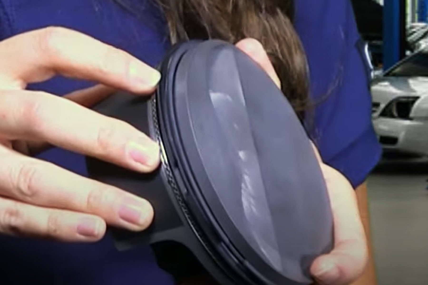
Generally, when measuring engine components, you would use the proper micrometers and measure to the .0001 inch. However, you can identify components with a simple .001 caliper, as we’ll show here. Plus, it’s a lot easier to carry a caliper with you, than a 0- to 6-inch mic set. To demonstrate, we’re going to go through and measure these “unknown” components from JE Pistons and SCAT Enterprises that came out of one of our other editor’s semi-mystery engines that he recently pulled apart.

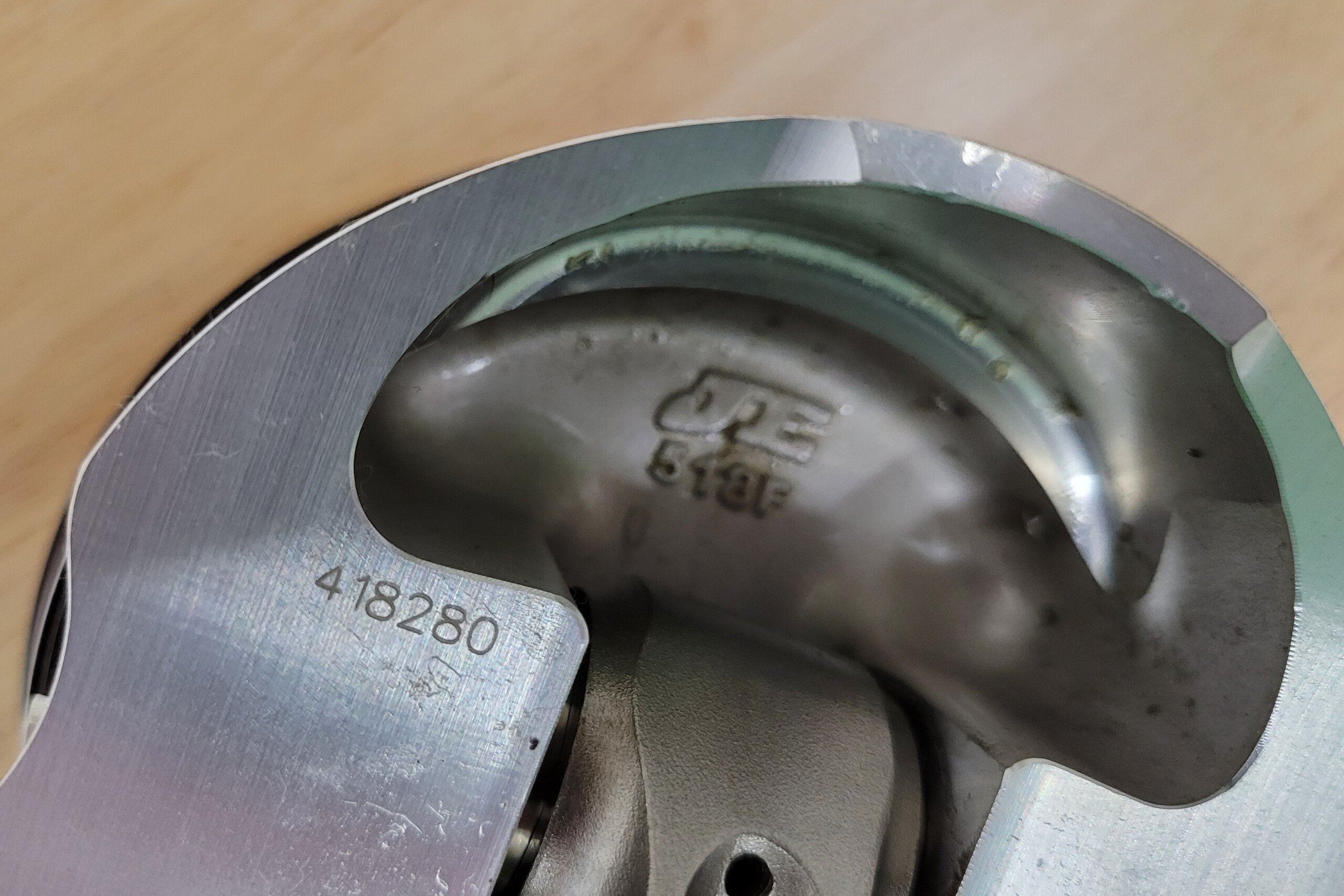
If you can identify a part number and a serial number, you might be able to get specs that way. JE has the ability to look up this combination and gave us some good information about the parts. However, we still measured everything because a lot can happen between it leaving the factory and when you run across it.

Identifying Pistons

To some, the idea of buying a used piston is akin to buying used underpants, but there are a lot of pistons on the market that have plenty of life left in them. The key is to make sure you know what you are looking at and for. The primary measurement for all pistons is the bore size they work with, or their diameter. This can be a little bit tricky and a little bit confusing if you aren’t familiar with measuring pistons.

You see, most pistons aren’t perfectly round, and the crown, which is the spot most would think to measure, isn’t where you measure a piston’s diameter. Each manufacturer will specify an exact location of the datum point, but in general, it’s 90 degrees opposite of the wrist pin, about half an inch up from the bottom of the skirt. If in doubt, you can measure various points above and below that half-inch mark to find the largest point, but it will always be 90 degrees opposite of the wrist pin axis.

Identifying pistons

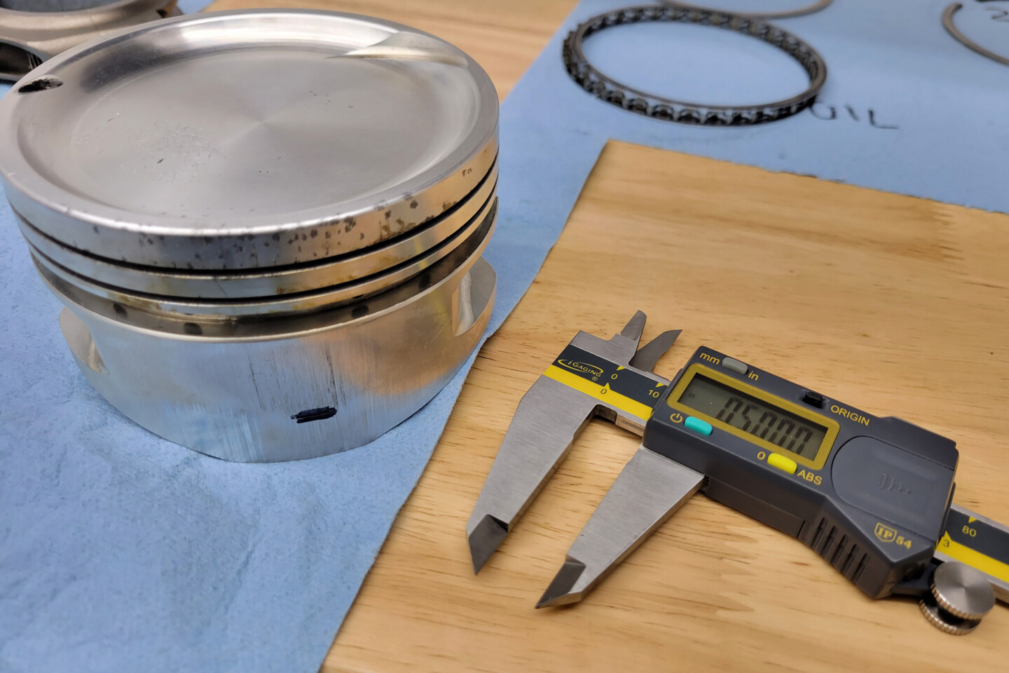
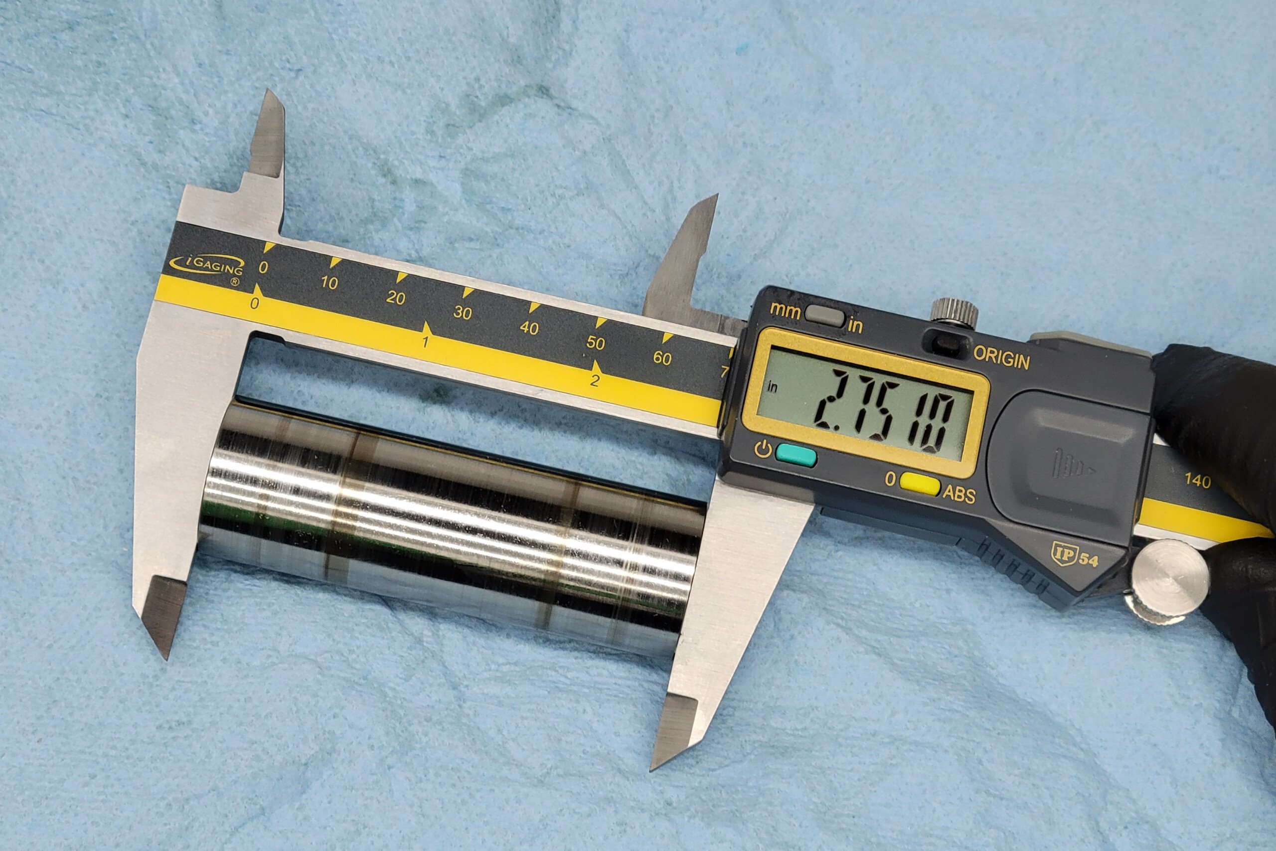
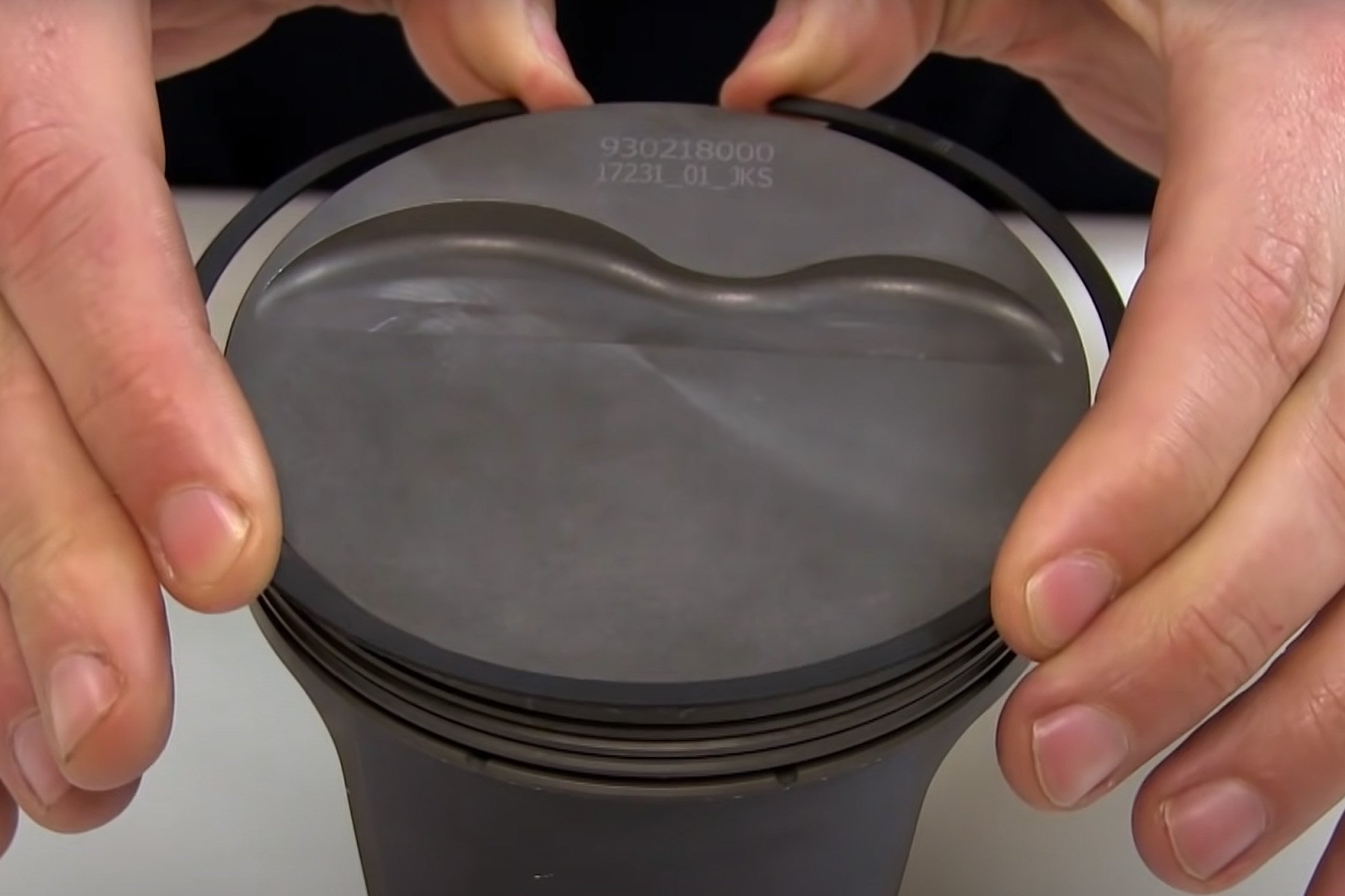
The datum line for JE pistons is .500-inch above the bottom of the skirt, 90 degrees from the wrist pin. So we Sharpied the area and then scribed a line exactly 0.500 inch up.

Now, the second tricky part of the diameter measurement is that it won’t match your bore size exactly. You have to factor in piston-to-wall clearance. Different piston materials will call for different clearances, so the actual measurement related to a given bore size will vary. Knowing these specs is crucial if you are trying to fit an already finished bore. There’s a little more leeway if you haven’t done the machine work yet, but you still need to know that there is a variance there.

For example, say you were looking for pistons to fit your 4.030-inch bore. If you were looking for a set of Hypereutectic pistons, you’d want a piston that measures in at 4.028 to 4.0285 to achieve the recommended .0015- to .0020-inch clearance. Conversely, if you were looking for a 2618 piston for that same bore size, you’d want a piston that measures more closely to 4.025 inches. If you didn’t account for piston-to-wall clearance in those measurements, and you threw a caliper on a set of pistons at a yard sale and saw 4.025, you might pass them up thinking they weren’t the right size for your project.

Placing the jaws at the datum point for both lines we got 4.025 inches. While that’s not accurate enough to measure piston-to-wall clearance, it’s accurate enough to say that these 2618 pistons are for a 4.030 bore.

Beyond Bore Size

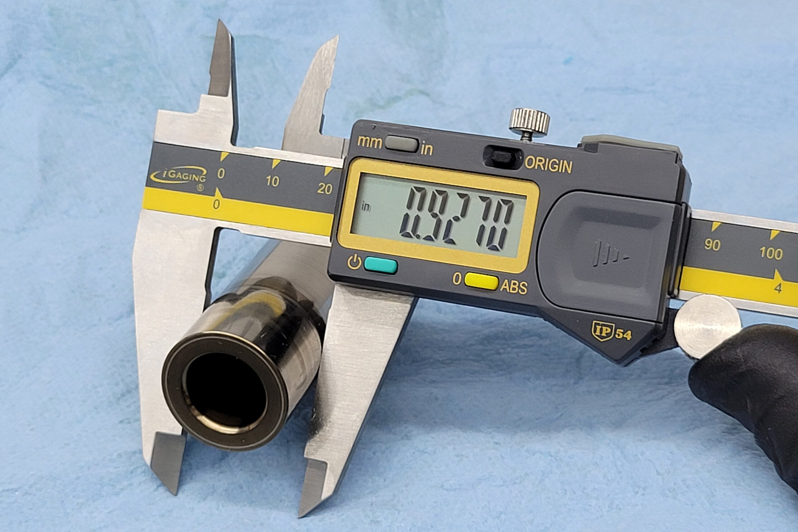
The next thing to measure is the wrist pin size. Usually, piston sets will come with wrist pins, so they will be easy to rough measure – just throw a caliper on them and that will tell you what their nominal size is so that you can match them to your connecting rod. Also, look for a marking showing the wall-thickness of the wrist pin, or toss the caliper on it. That spec can be important to your build.

If the wrist pins aren’t included, you’ll want to rough measure the diameter of the wrist pin bore of the piston, again, to make sure they match your rods. If, for some reason, you are looking at wrist pins by themselves, make sure you measure the pin’s length as well, as that can vary from piston to piston, in some designs. If you need a .927-inch diameter 2.500-inch long pin, a 2.750-inch long wrist pin won’t do you much good.

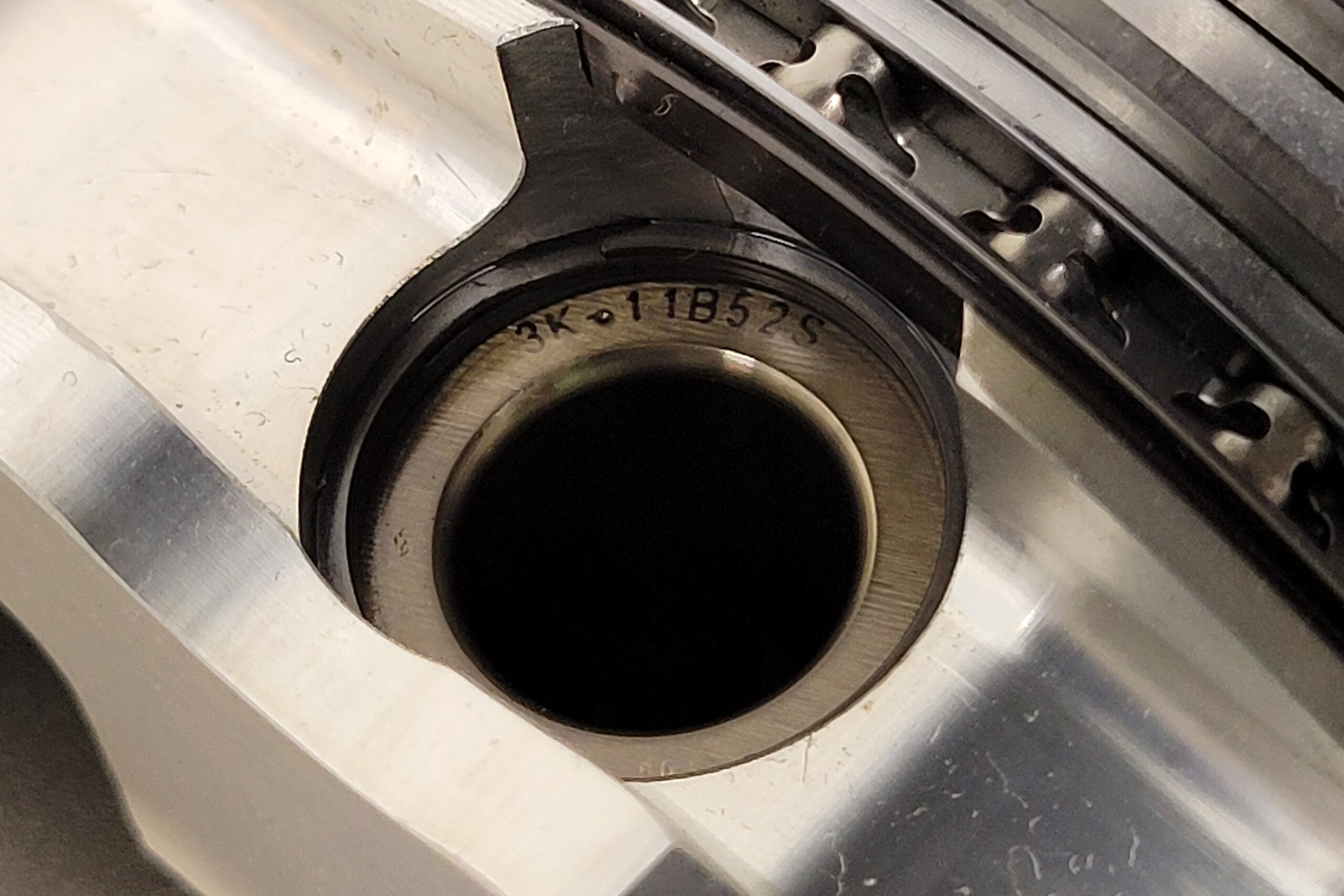
Finding a part number on the wrist pin is the easiest way to identify them. However, measuring OD and length, along with wall thickness is easy enough with a set of calipers and will get you plenty close to identify them.

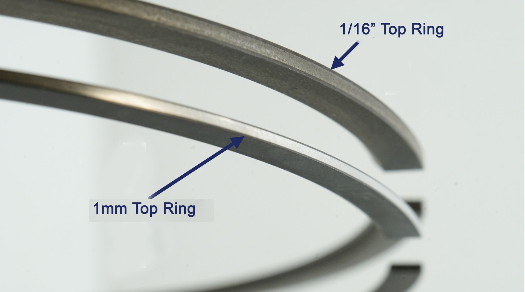
Next, we’ll need to determine the ring package. For rough measurement in a pinch, you can use the inside jaws on your caliper, but for more precise measurements, you’ll want to use pin gauges, feeler gauges, or an inside mic. Not only do you want to measure the size of the top, second, and oil ring grooves, you’ll want to measure, or at least pay attention to their spacing and location on the piston, which might be a concern for your combination.

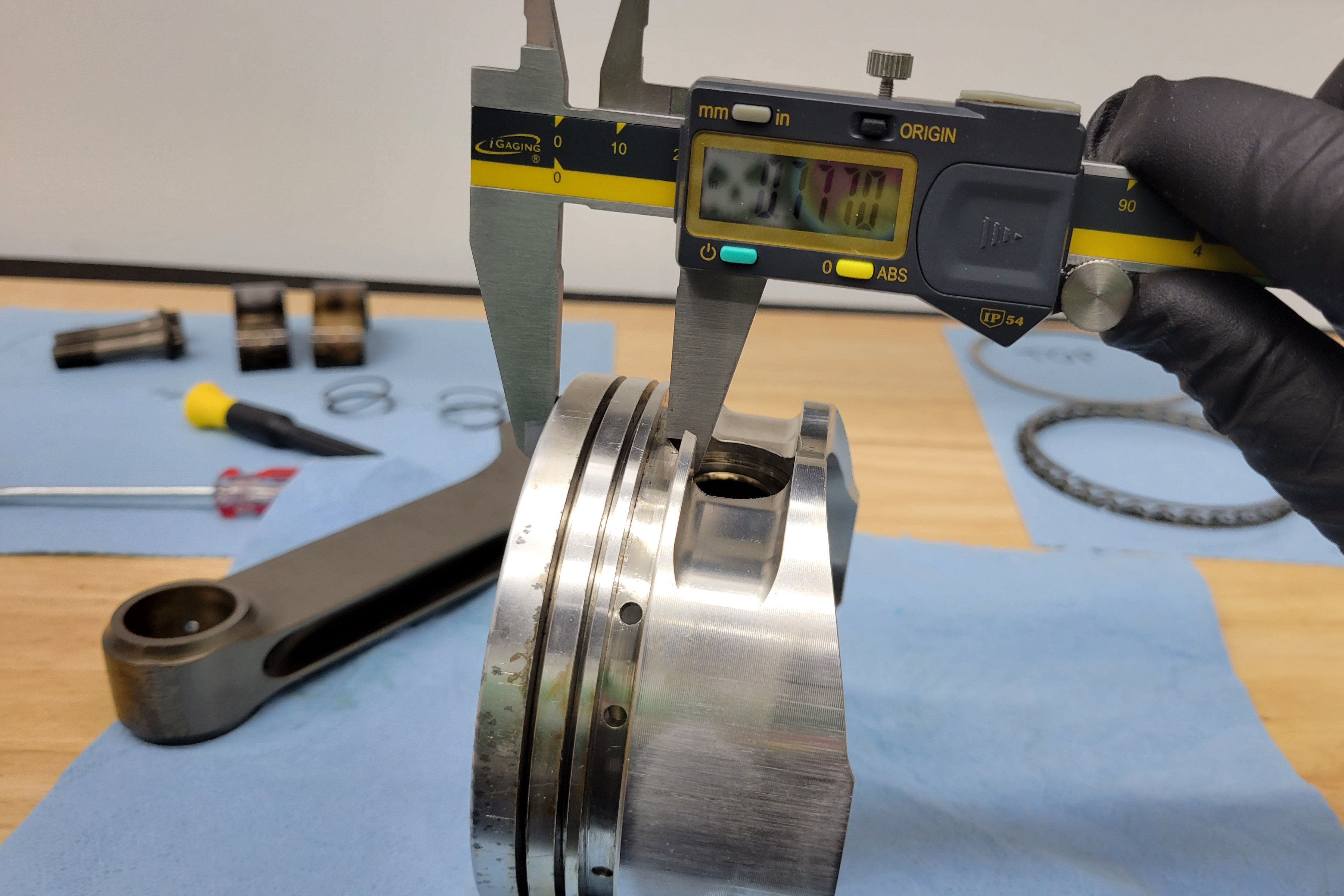
You’ll also want to note the compression height of the piston — the distance between the center of the wrist pin bore and the crown of the piston. This measurement, combined with your crankshaft’s stroke and connecting rod length will determine the piston’s location in the bore at TDC. If you’re matching to a set of existing rods and crank, this will be incredibly important.

If you have the rings on the pistons, measuring the ring pack is straightforward (left). However, if they are bare pistons, you’ll need to measure the ring grooves themselves. Calipers will get you in the ballpark, but a set of pin gauges or feeler gauges would be much finer and could identify any wear more easily.

If you’re fitting the rest of the combo around the pistons you got for a smoking deal, you have a little more flexibility here. However, you also need to consider the application as well. If you are going to be feeding tons of boost to the engine, you don’t want a piston with an exceptionally small compression height. Conversely, if you’re looking to turn significant RPM with the engine, you don’t want a huge, heavy slug in there.

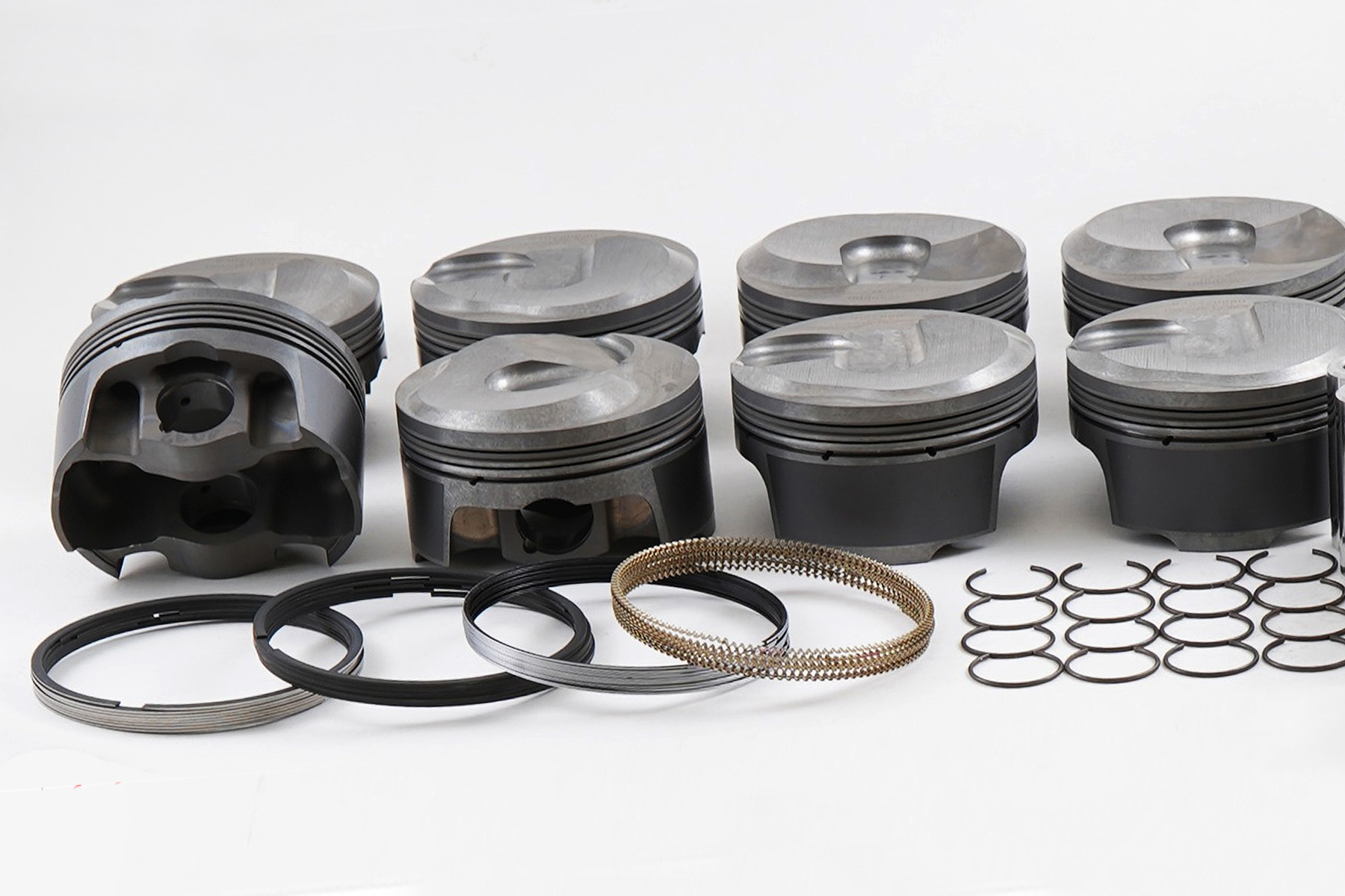
The last area you need to pay attention to is the crown of the piston. The first thing is the valve-relief arrangement. Some pistons have valve reliefs designed for the valve angles of specific cylinder heads, to the exclusion of other, potentially more standard valve layouts. The second thing to pay attention to is the dome volume. The three main configurations are flat top, dome, and dish (or reverse dome) pistons.

measuring compression height

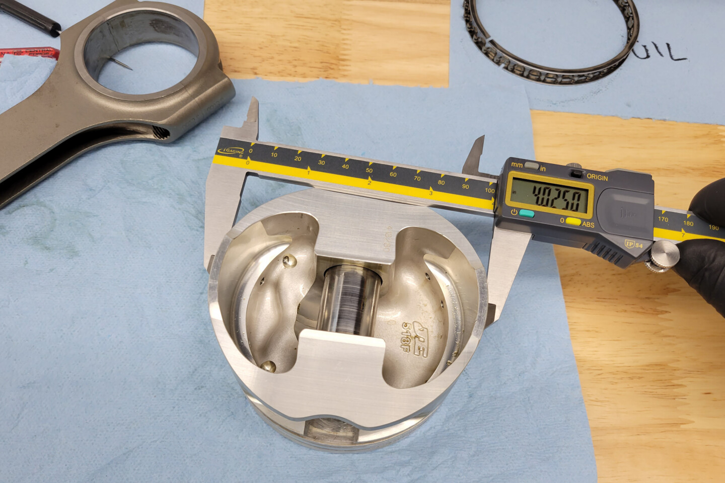
The compression height of a piston is a very important spec. By measuring from the crown to the top of the wrist pin bore, and then adding half the diameter of the wrist pin, you get the compression height. Compression height plus rod length, plus half of the crank stroke, subtracted from your block’s deck height will tell you whether the piston sits in or out of the hole.

As the name suggests, a flat top piston is flat, with a 0cc volume (you will want to account for the volume of any valve reliefs present, however). A dome piston is one that has material above the crown, designed to reduce the combustion area and raise compression. A dish piston is the opposite of a dome piston, where there is a void in the crown of the piston designed to increase the combustion volume and lower the compression ratio.

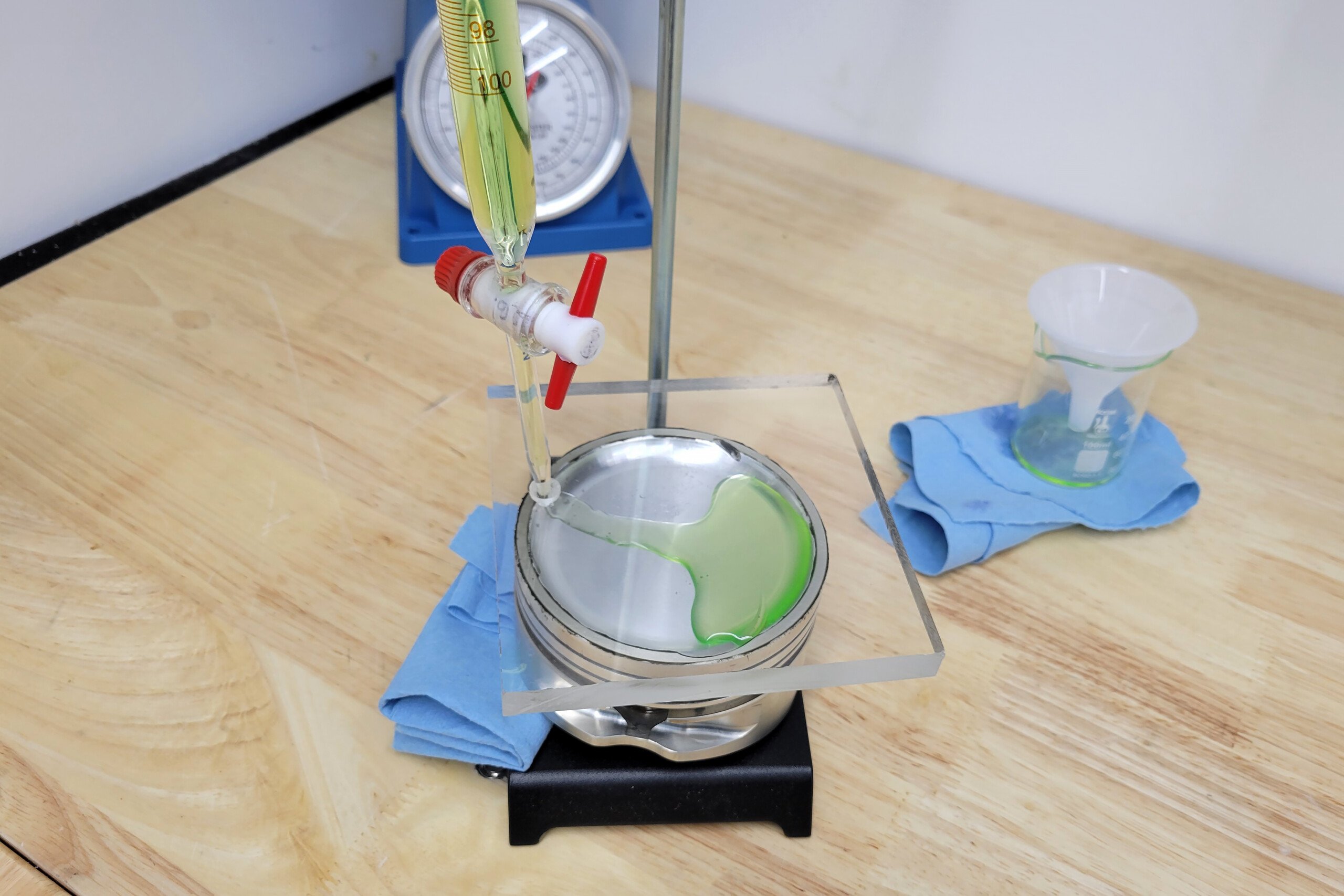
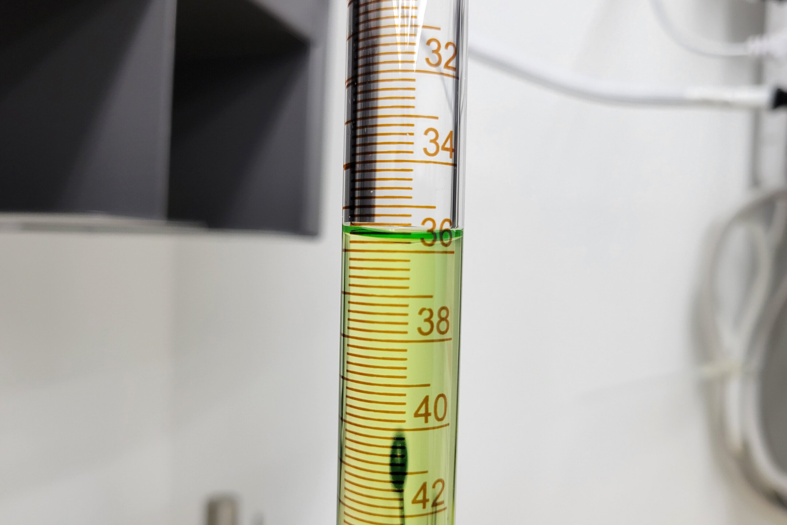
Measuring the exact dome or dish volume of a piston is important. Normally that information will be supplied by the piston manufacturer, but it can be measured at home. For a dished piston, it’s exactly the same process as CCing a cylinder head. For a dome piston, it’s the same process with a little extra math involved, where you calculate the theoretical volume of a cylinder of fluid, and then subtract the actual measured volume. The difference is the volume displaced by the piston’s dome.

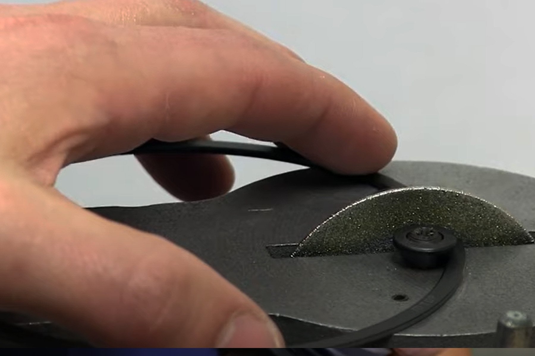
CCing a dished piston was quite easy in this case, since the valve relief didn’t break the seal. Measuring dome volume is a little trickier, but very similar. This piston came out to be a 35.8cc dish. Quick math says that these components, with a 4.100-inch stroke crank, would come in right about 8.8:1 compression. Makes sense for the era this engine was originally built.

Measuring Unknown Rods

Moving on to the connecting rods, there are definitely fewer measurements to take, but they are just as crucial. You aren’t going to be able to determine the material just by looking at the rod, but you can determine what rod shape it is, as well as whether it’s a press-fit rod or has a free-floating brass bushing in it.

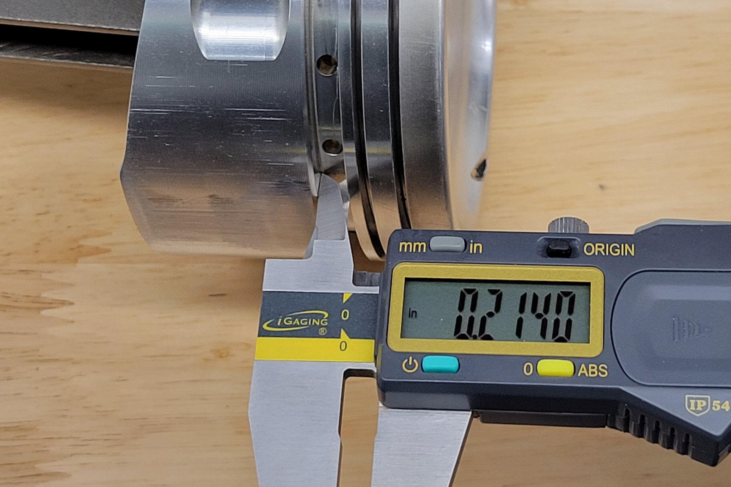
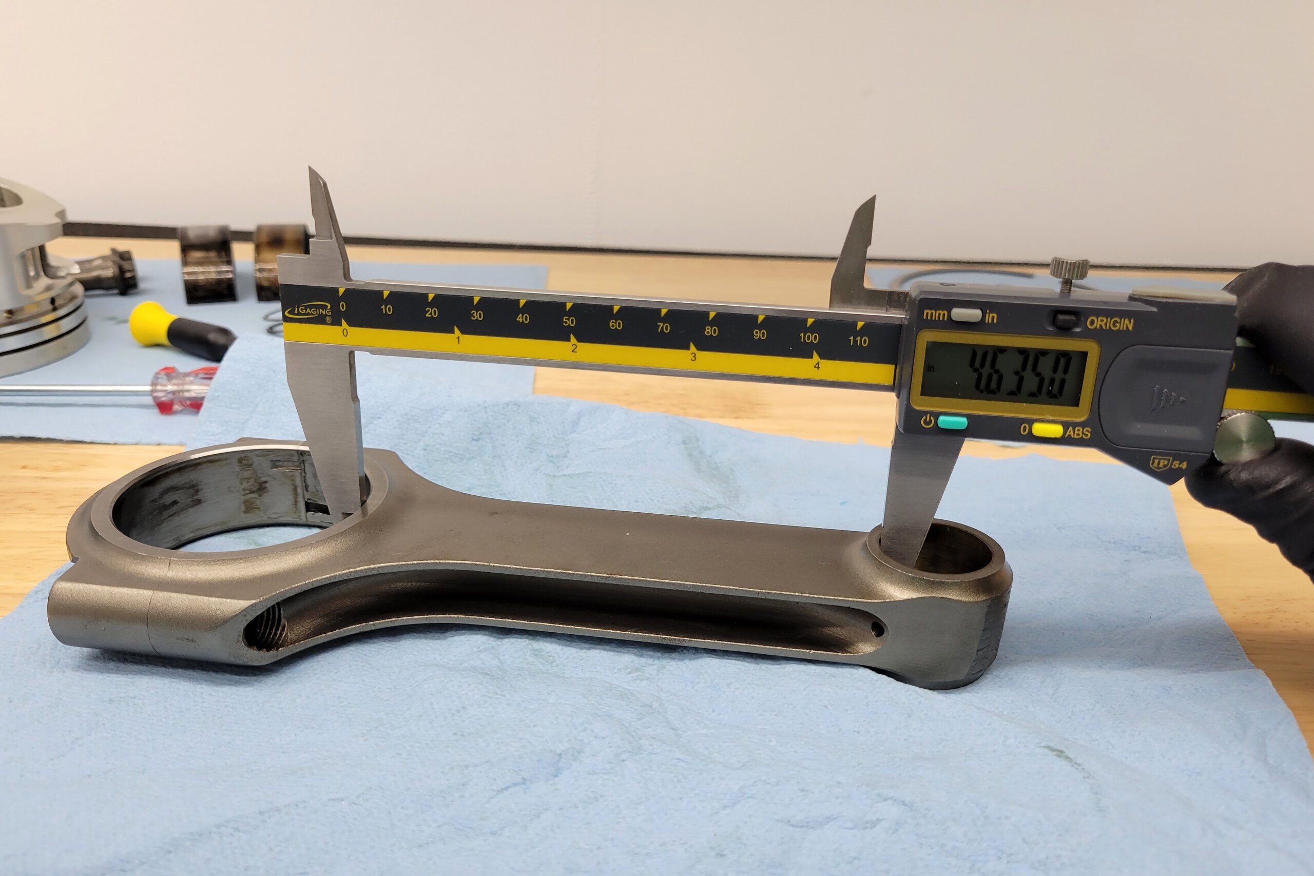
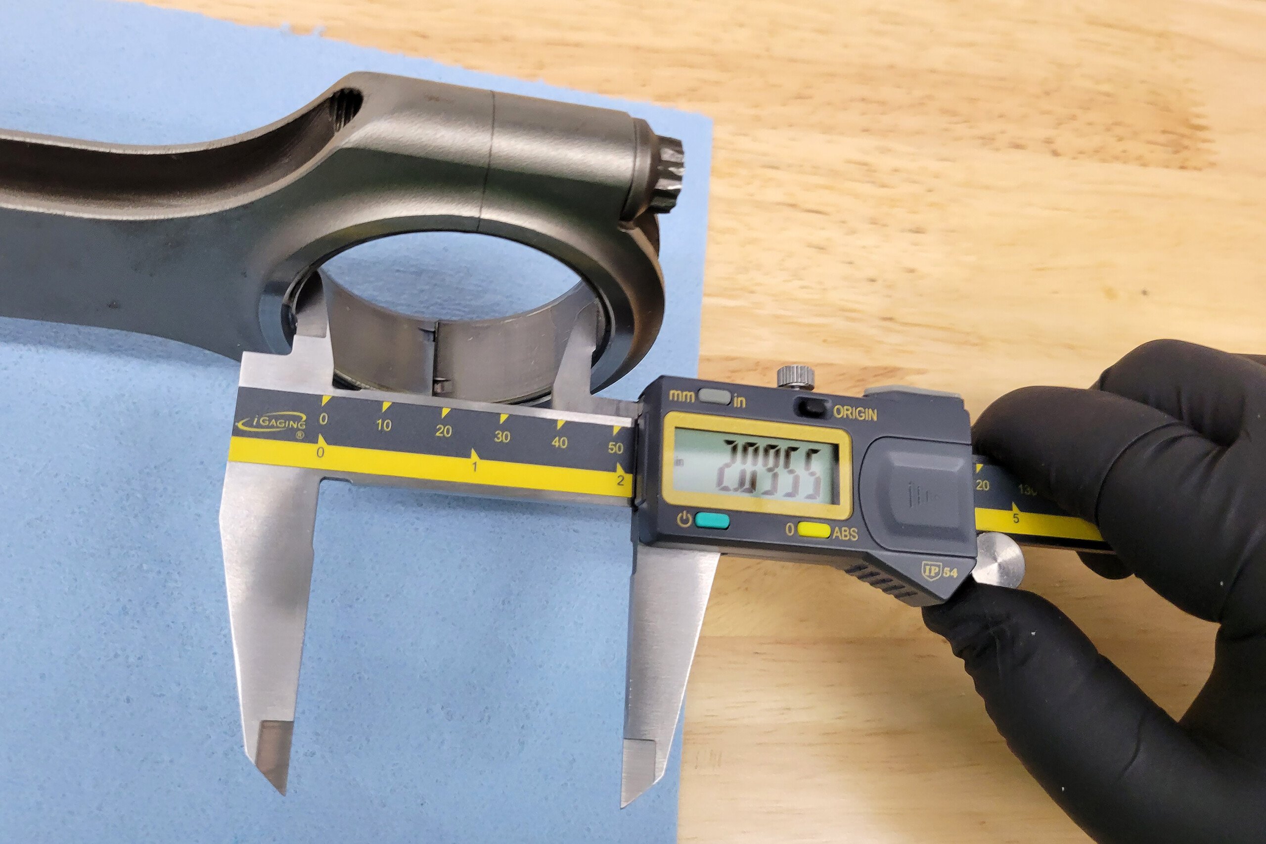
A rod’s length is actually a measurement from the center of the wrist pin to the center of the crank pin. In order to calculate that, you can add half of the wrist pin diameter (since we know it from above), a measurement of the rod main section (left image) and then half of the big end diameter (center image). As long as you take both the big end and body length measurements either with or without the bearing, you’ll get the right rod length. Notice in the photo on the right that there is a measurement with a bearing. That gives us the crank journal diameter.

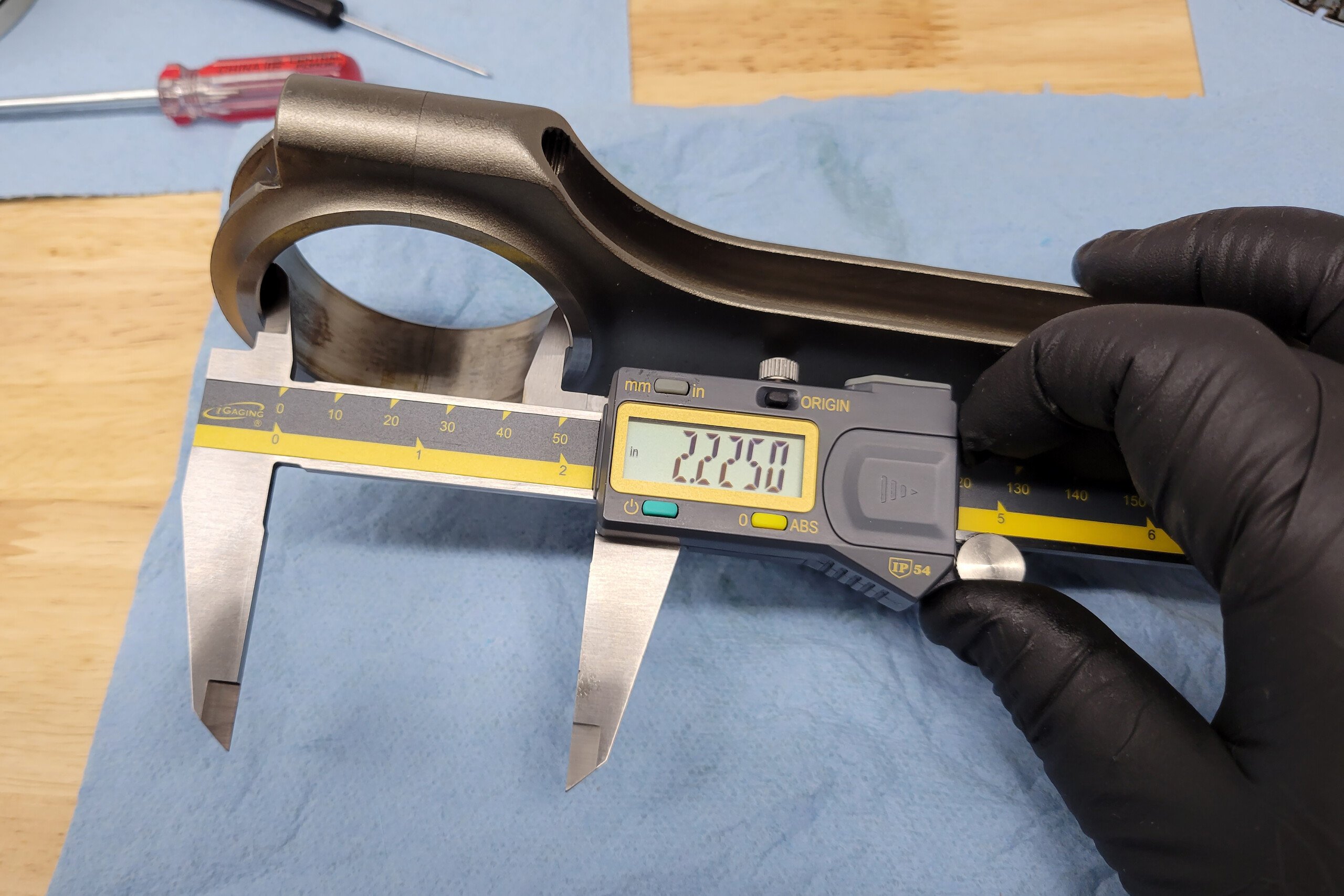
What you can and will need to measure to identify the rod are the two holes in the rod, and the distance between them. The first two are relatively straightforward. Using the inside jaws of a caliper, you can get a fairly accurate idea of the big end (crank pin) diameter and the small end (wrist pin) diameter. The next critical component requires a little bit of math to get.

Chances are you’ll be using a six-inch caliper, which means you won’t have the reach to measure everything in one shot and that’s OK. What you will do is measure from the top of the rod journal housing to the bottom of the wrist pin hole. You will then combine that number with half of the wrist pin diameter and half of the rod journal diameter. That will give you the center-to-center length of your connecting rod.

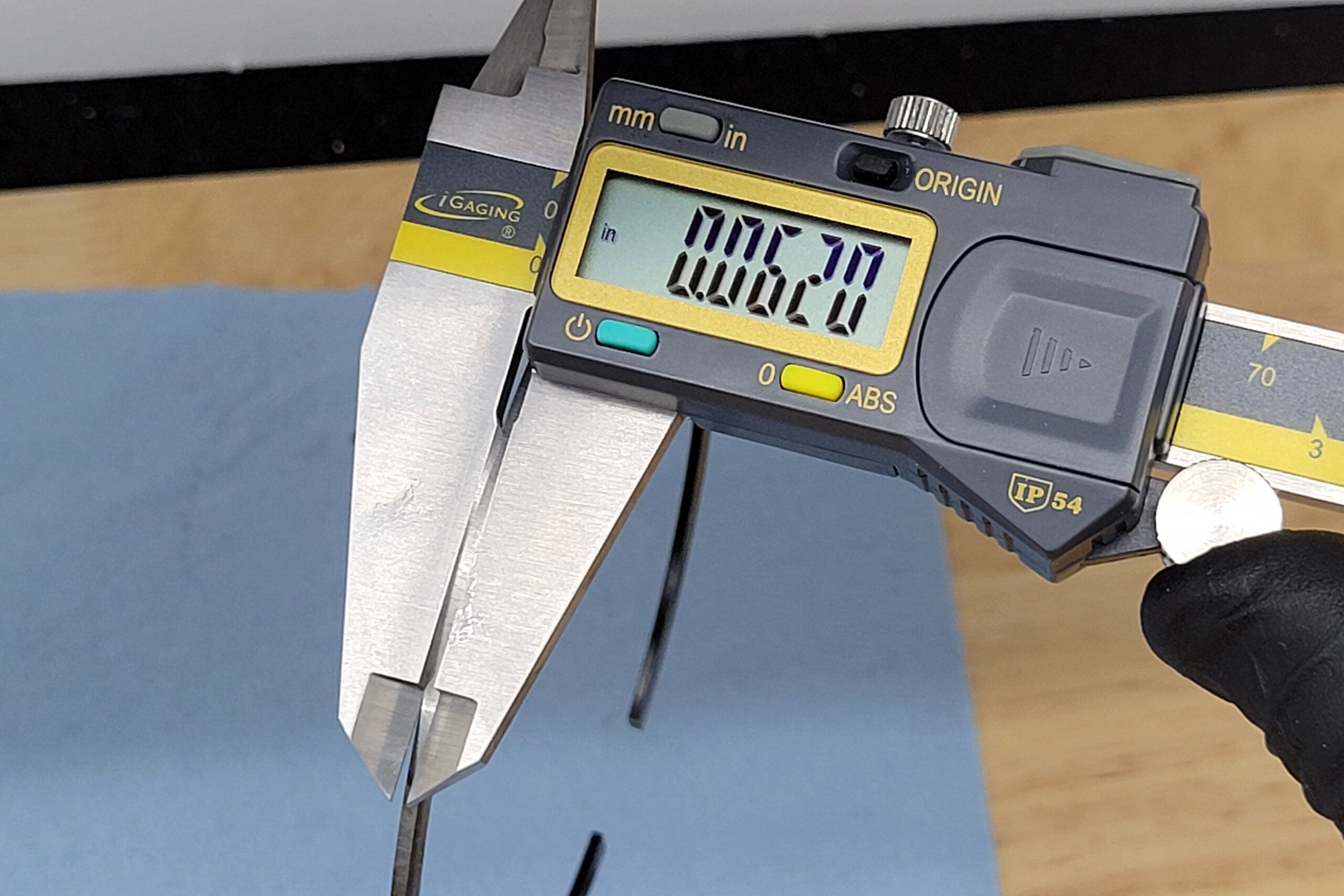
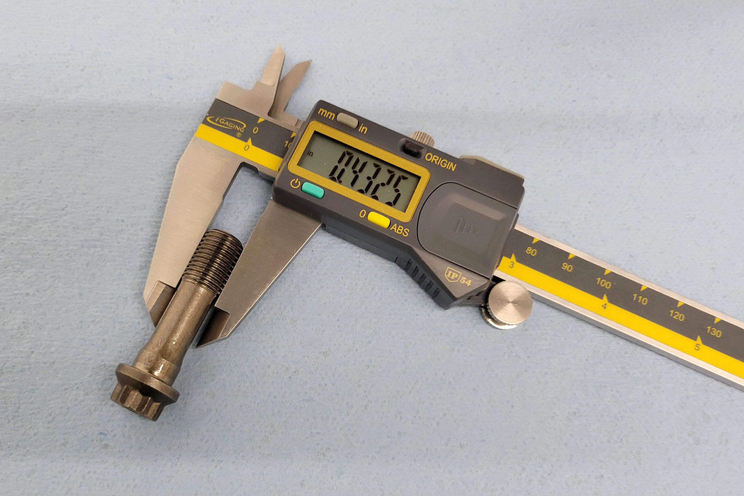
Luckily these rod bolt tell us almost everything we need to know: Bolt manufacturer, bolt material, and rod manufacturer. We still need to measure to find the bolt’s diameter.

The next parameter isn’t necessarily critical to fitment, but is important to performance, and that is rod bolt diameter. Simply put the caliper on the rod bolt and find the diameter. Seems simple, but if we didn’t include it, invariably someone would point out that we didn’t address the rod bolts.

And that’s it. With all those measurements you will be able to quantify anything without a part number, that you need to identify. However, that does bring up the point, that the first thing you should look for on the mystery parts is a manufacturer and a part or serial number. Some manufacturers will be able to give you an entire suite of data based on those numbers alone. Of course, measuring is the most accurate method, since a lot of things can happen once the parts leave the warehouse. They are used, after all.

Posted on Leave a comment

The Advantages Of Running Thinner Piston Rings

The quest for more engine efficiency has auto manufacturers adopting thinner rings for greater efficiency when it comes to the family sedan. MAHLE has also embraced this technology, and much more in its motorsports division.

MAHLE Motorsports adopted a new thinner ring technology for performance and racing applications a few years back. The next stage for MAHLE is to educate racers about how these unique rings function and spell out the benefits for their next engine project.

mahle motorsports, piston, piston ring

This side-by-side example of piston designs compares a 1.5mm, 1.5mm, and 3.0mm ring pack (left) beside a 1.0mm, 1.0mm, and 2.0mm ring pack MAHLE cinches up the ring pack with thinner rings, versus leaving the ring grooves in the same location as they would with thicker rings.

We asked Joe Maylish, program manager for the MAHLE North American motorsports division, if material advancements sparked the new narrow rings compared to the thicker rings that have been the norm in the high-performance world for many years. His response is, “Yes, and more.”

Materials And Manufacturing Techniques

“Material is one of the factors,” says Maylish. “MAHLE produces a huge volume of piston rings per year for automotive manufacturers and other applications. The volume of specialized raw materials we use with rings on the OEM side allows us to also engineer and manufacture effective rings for motorsports with an extension of that cutting-edge technology.”

Typically, piston rings can be constructed with different raw materials such as alloys of cast iron and varied steel materials, along with a variety of coatings on the ring face, like gas-nitriding, adding wear resistance to the face of a ring.

mahle motorsport, piston, piston rings, mahle piston              rings

MAHLE is a well-regarded supplier of coated pistons for motorsports. Their Power Pak piston sets have the option of their “thin ring” technology for performance and racing enthusiasts.

Engineers at MAHLE have developed a 1mm top compression ring , 1mm second compression ring , and a 2mm oil control ring assembly pack that minimizes friction and maximizes sealing between the rings and your engine’s cylinder walls.

“Few would argue against the ability of thinner rings to free up horsepower in the right application,” states Maylish. “The typical concern from the racing world is usually first if they will last, and second, are they worth it? So, we asked our engineering team these questions to be able to convey answers to the racers.”

A 1.0mm compression ring can have up to 50-percent less mass compared to 1/16-inch rings. That equals a 50-percent reduction in the inertial force on that individual ring, plus an increased ring-to-piston groove seal.  

Durability

The modern ring pack is much more than just “thin.” In a departure from the typical materials, MAHLE’s metallurgical engineering advancements for these thinner ring packs rely on high-strength steel alloys. MAHLE’s new steel creates a ring far more durable than any cast-iron or ductile-iron option, which achieves proper sealing, thinner size, and less wear in motorsports applications.

The E9254 chrome-silicon steel used in the 1mm top ring successfully minimizes friction and is 35-percent stronger than any cast- or ductile-iron option. With this improved steel comes the ability to produce thinner rings that match the strength of thicker iron rings. The chrome silicon steel contains metallurgical advantages. The materials allow it to achieve ultra-flat ring flanks and a precision finish without machining damage. These two materials also maximize cuff resistance and ring-to-piston sealing.

Less tension by these rings throughout all four strokes of the engine results in less wear on the face of the rings, less drag on the rotating assembly, and less wear on the cylinder walls. – Joe Maylish, Mahle Motorsport

Reduced reciprocating mass is another strong point of the ring. With less mass, the piston and ring can travel up and down faster with higher RPM because of the lessened inertia points at the top and bottom dead center. According to Maylish, at these inertial points, this weight reduction can reduce or eliminate what is called “ring flutter,” which can decrease the ring-to-piston groove seal.

“Granted, you can apply these better materials to any size rings, but that will not overcome the differences in the cross-sectional area with the thinner rings,” Maylish says. “Those smaller dimensions make the rings lighter and more conformable.”

Maylish adds, “This means you can design rings with less radial tension to achieve the same or better combustion gas sealing than a thicker ring. Furthermore, less tension throughout all four strokes of the engine results in less wear on the face of the rings, and less wear on the cylinder walls.”

Steel is also a better conductor of heat and can withstand a longer duration of high-temperature operation without concern for the rings losing tension.

The PowerPak piston line from MAHLE Motorsport offer a long list of included features that were once reserved as options or supplied by separate companies. Off the shelf, these pistons feature full crown machining and coated crowns and skirts. Now, the PowerPak piston sets are available with this new ring technology.

Ring Face Coating

The top ring in the 1.0, 1.0, and 2.0mm pack includes MAHLE’s patented HV385 thermal spray process. This coating is applied to the face of the top ring to improve bond strength of the 9254 steel underneath, as well as durability, and scuff resistance.

“This sprayed material actually becomes embedded into the top ring,” Maylish discloses. “The material is applied through a supersonic, thermal spray process with a liquid-oxygen-powered gun. The HV385 material impregnates itself into the ring face.”

Ring Tension

The fundamentals of all ring designs call for the ring to be formed into a larger diameter than the mating cylinder bore. When installed, the compressed ring tries to expand to its natural diameter and pushes against the cylinder wall; that is called “tension.”

“The conformity of the steel material means you can design rings with less radial tension to achieve the same or better combustion gas sealing than a thicker ring,” Maylish explains. “Older ring designs rely on a comparative ‘brute’ tension force for piston sealing.”

MAHLE’s thermal spraying consists of fine droplets of HV385 material exposed to high temperature and sprayed with supersonic velocity into the face of the top ring made of 9254 steel. Electric or manual ring filing procedures for setting your instructed ring gaps use traditional methods.

The second 1.0mm ring is a reverse-twist taper-faced steel, and the oil rings are standard-tension oil control rings, all with a specific tension designed into them.  

Optimizing Seal

The engine bore is not perfectly round for any engine under power. The stresses on the bore — mechanical loading, deformation, and high temperatures — distort the bores. This distortion is typically measured in microns. It sounds minute, but those stressed bore shapes allow cylinder pressure to escape the combustion area past the rings.

MAHLE pioneered computer simulation software and other development tools that successfully minimized friction without sacrificing sealing capabilities. Maylish states, “These rings’ ability to conform to the cylinder walls increased measurable horsepower gains on the dynamometer during our development process. Furthermore, less tension throughout all four strokes of the engine results in less wear on the face of the rings and less wear on the cylinder walls.”

The PowerPak piston sets from MAHLE Motorsports are available with traditionally dimensioned ring sets or the newer 1.0, 1.0, and 2.0mm options. Here is your typical big-block Chevy piston set with the thin ring option.

Strengthen The Piston

These thinner ring sets also allow the MAHLE engineers to develop new piston designs with shorter ring packs that eliminate the wrist pin bore from intersecting the oil ring groove. This clearance is a big plus for many small-block and LS engines. Now, the pin bore has space to sit below the oil ring groove, eliminating the need for support rails, which improves overall piston strength.

New technology for racing is on a constant quest for stronger, lighter, and better-performing designs. There is no question that these thinner MAHLE rings are an effective addition to the motorsports world, since they meet those criteria.

Not just a fad diet, the results from MAHLE’s dyno research and scores of other independent tests by performance engine builders cite the multiple benefits of piston and ring assemblies to not just be smaller, but to add a critical conformity between the rings and the cylinder wall. This “diet” provides a better seal to prevent compression gases from escaping around the piston, the biggest single job rings have.