
DECEMBER 15, 2023
This is the story of opportune meetings, overcoming odds, and unrelenting levels of girl power. It is also the story of an undersized Honda Civic, its equally tiny engine, and the tenacity that it takes to become one of the fastest front-wheel-drive drag racers on the planet.
For Process Development Manager, Nichole Elff, adrenaline has been a core component in her life for as long as memory serves. So when she was introduced to the import scene back in college, her interests pivoted from horseback riding, to customizing cars with friends on the weekends. The following twenty-year import automobile love affair would see Nichole start with a 1994 Acura Integra rocking basic bolt-ons, to what what you see here today: A dedicated XFWD championship Honda race car driver with stacks of wins to her name, including the title of 2nd fastest FWD female driver in history.

All of this has been made possible by a surprisingly small powerplant: A 119ci 4-cylinder B18 Honda engine that puts down around 1,500 wheel-horsepower. If our math is correct, that averages out to an astonishing 12.6 horsepower per cubic inch. Compare that to a Pro Modified car, which is averaging anywhere from 7 to 8 hp/ci, and you can see the performance appeal of this Honda platform. However, what you don’t see are the tuning and engine-building challenges of running a dedicated race program that can safely and consistently supply these extremes, which as Nichole explains translates to, “…overbuild, demand high quality, and constantly seek out the weakest link.”
These values have also helped determine how Nichole’s Civic engine gets rebuilt after every other event or so. For as she is quick to admit, there is always room for improvement on her overbored B18C Honda motor, with the latest and greatest being of particular interest to us here at EngineLabs.

Elff’s best time in her 1992 Honda Civic is a 7.78 at 196mph, which at the time of this writing, makes her the seventh-quickest XFWD competitor in the world, and the second-fastest FWD female driver of all time.
Indy Racing and High-Speed Honda Goals
As for the racing side of this story, that all starts way back in 2006 when Nichole moved to Indianapolis. It was there that she became part of a car forum called IndyHP, where she met her eventual husband, Damon. A 2007 trip to a NOPI Drag Racing Association event marked Nichole’s first time seeing ProFWD and SFWD racing, and it blew her mind that these cars were running nines in the quarter-mile. An event that left such a memorable impression, that she returned home, fully determined to start her own SFWD Honda Civic build.
Flip forward a decade, and Nichole was still sitting in the grandstands. The year was 2018, and while she had been actively competing for years, her Honda was just a tenth off of the minimum ET requirement to be labeled as a True Street WCF competitor. The following year, she officially qualified for WCF, where she made it all the way to the quarter-finals that year. She told herself that if she broke cage certification (8.50) it was time to jump head-first into drag racing. She proceeded to run an 8.49 in the first round of eliminations and that pretty much changed everything.

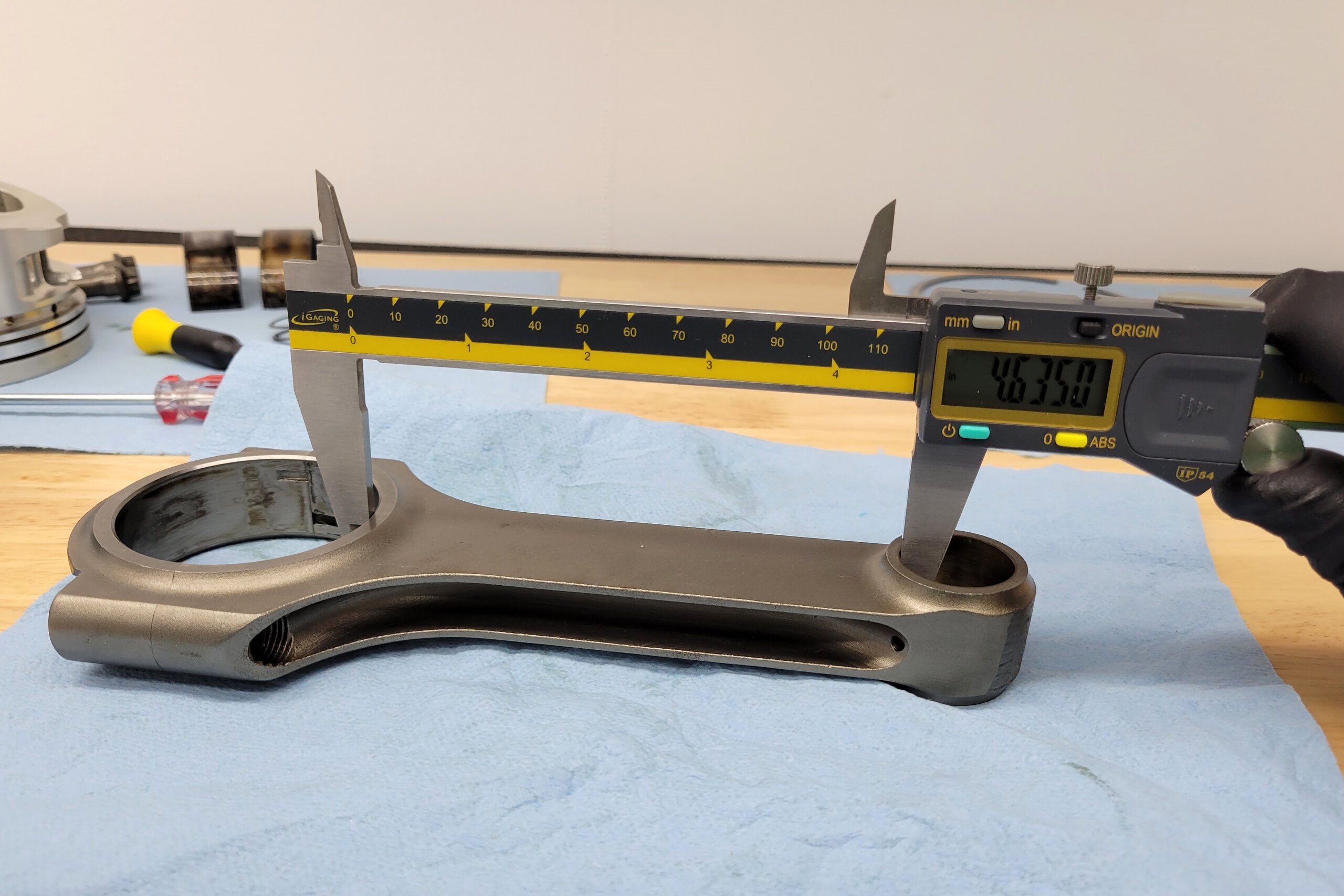
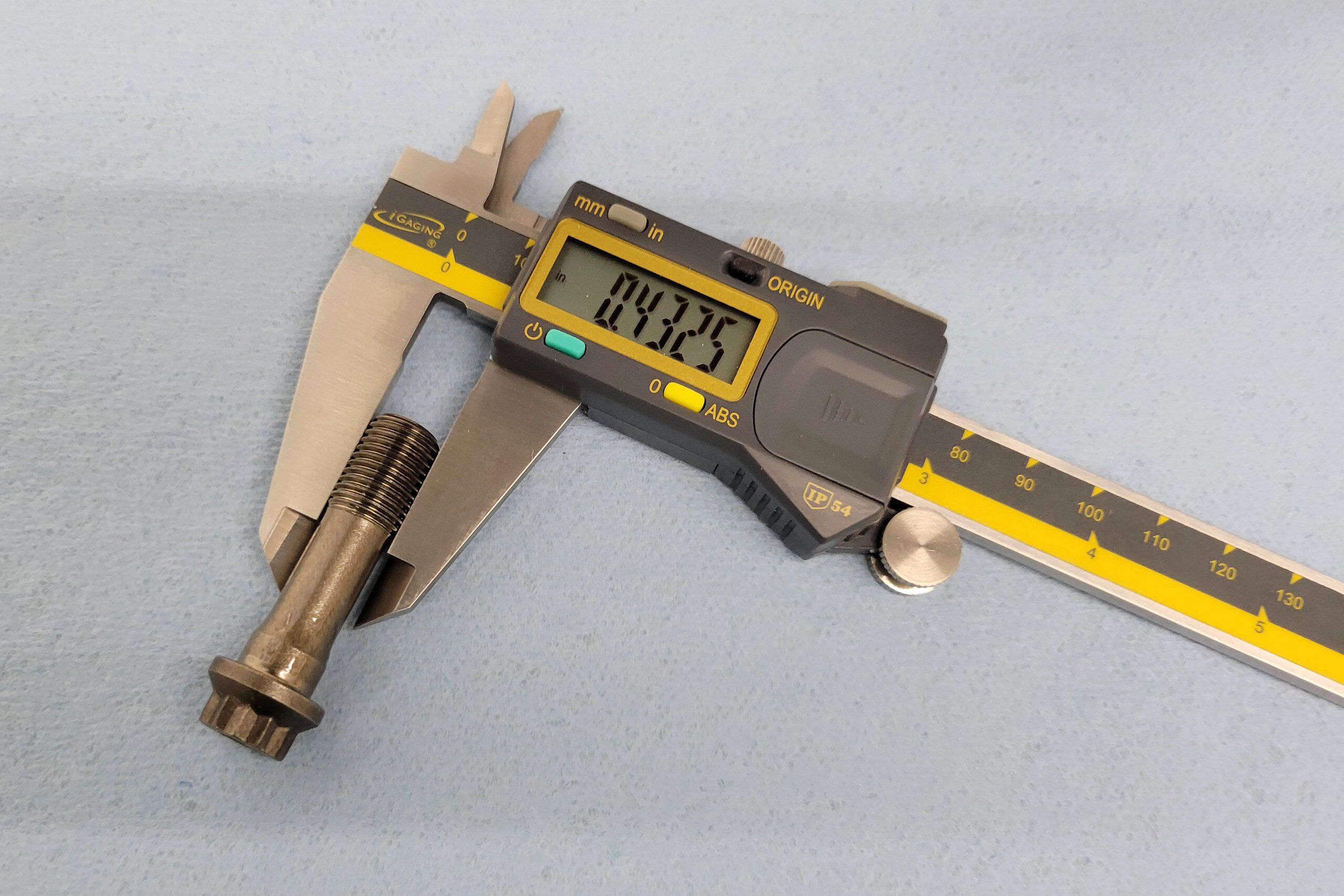
King offers rod bearings for aluminum rods with locating dowels. These extreme-duty components are required for such insane cylinder pressures.
The following year, in 2020, Nichole bought a fresh Honda Civic chassis, which quickly transformed into the “Miss PSI” car you see today. Come 2021, Nichole’s husband left professional racing so that he could focus full-time on his wife’s drag racing passion while growing his tuning presence via his business, Demon Motorsports. This decision proved fruitful, and that year brought with it runner-up finishes at the car’s first two events, before finishing off the season with the couple securing a WCF True Street win.
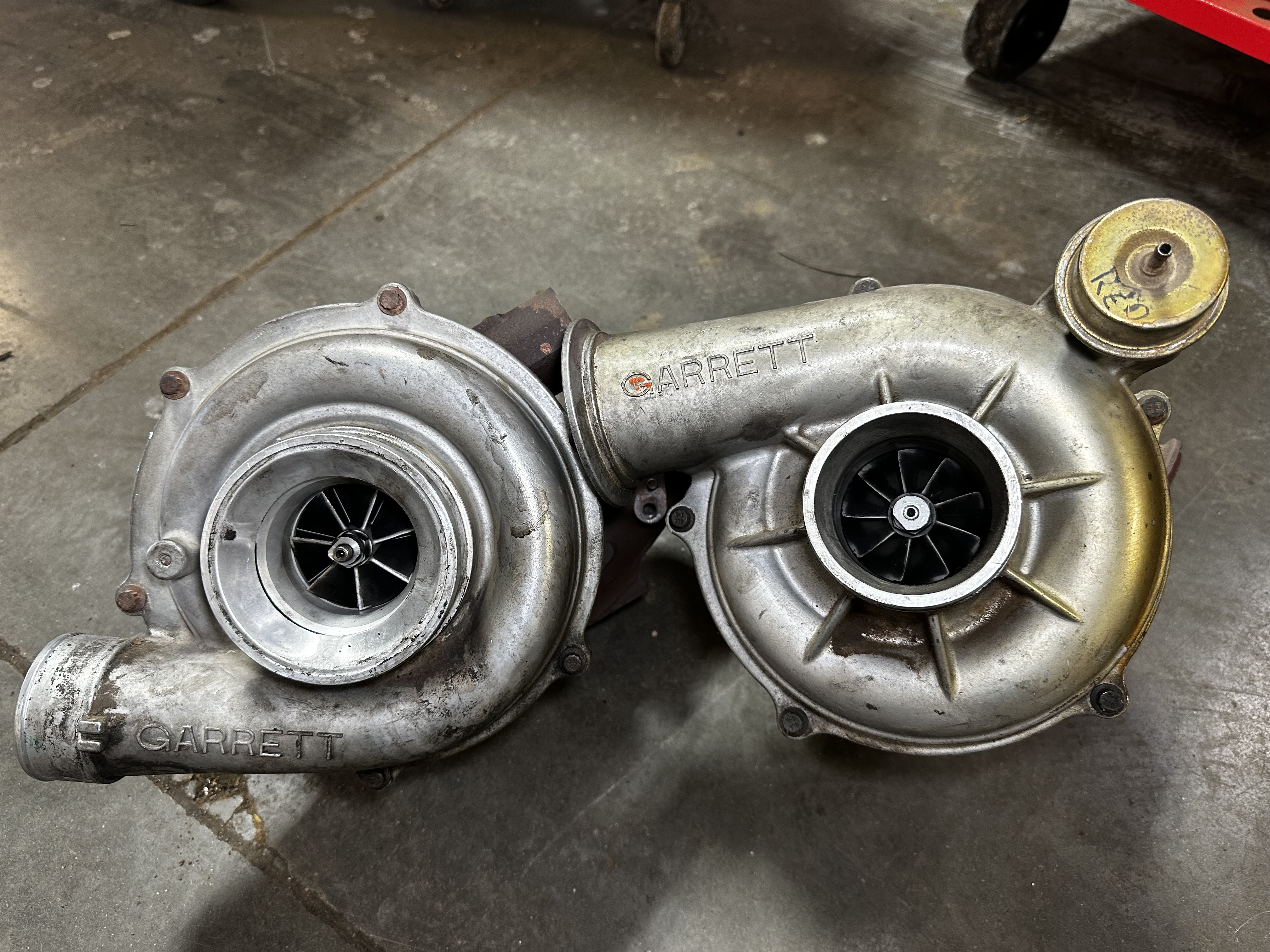
By 2022, Nichole and Damon had swapped in a much larger Precision Next Gen R 73.9 turbo to help break into the elusive seven-second zone. An accomplishment that would eventually be obtained during a 2022 FL2K qualifying round, making Nichole the first female in XFWD history to run a seven-second pass. Later in that same event her Honda ran a 7.84 and put its driver on the world’s top 10 list. 2023 brought with it a 7.78 at 196mph pass, thus making Miss PSI the 7th fastest competitor in the world and the 2nd fastest FWD female of all time.

The XFWD class is full of gear-banging adrenaline junkies that are constantly balancing the knife edge of performance, traction, and guts.
XFWD FTW PPL!
Being that this is an “XFWD” (Xtreme Front Wheel Drive) Challenge program we speak of, one of the biggest challenges is keeping the engine alive long enough to go the distance and compete in all rounds. Having enough performance left in the tank to compete in the final rounds, and occasionally turn things up a notch remains a concern at every race event.
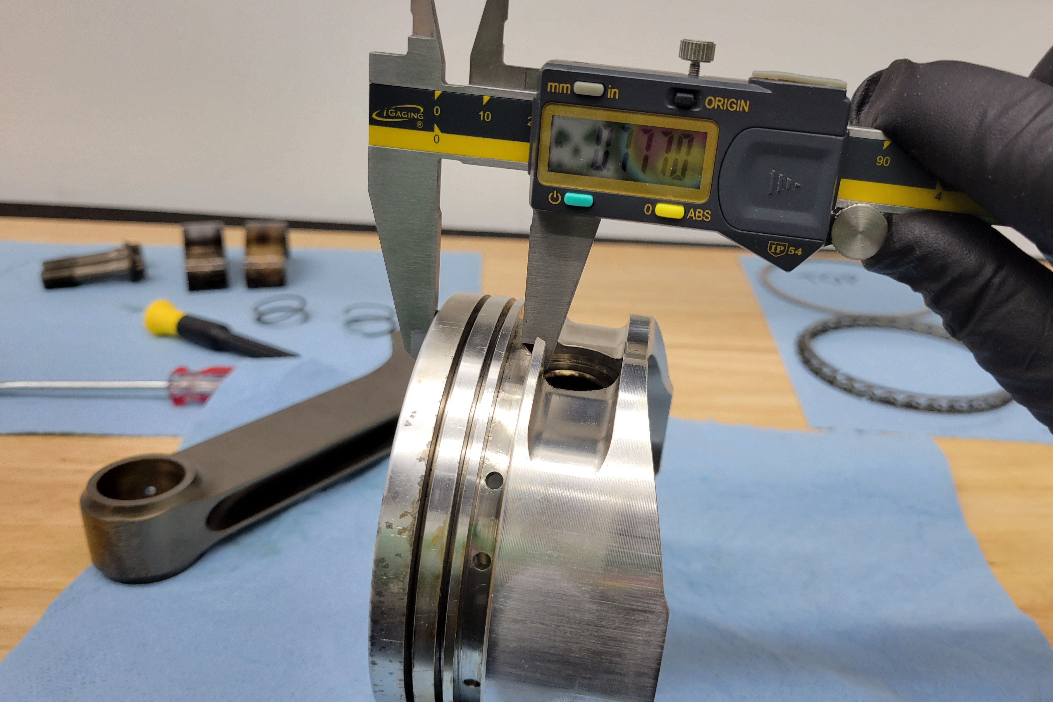
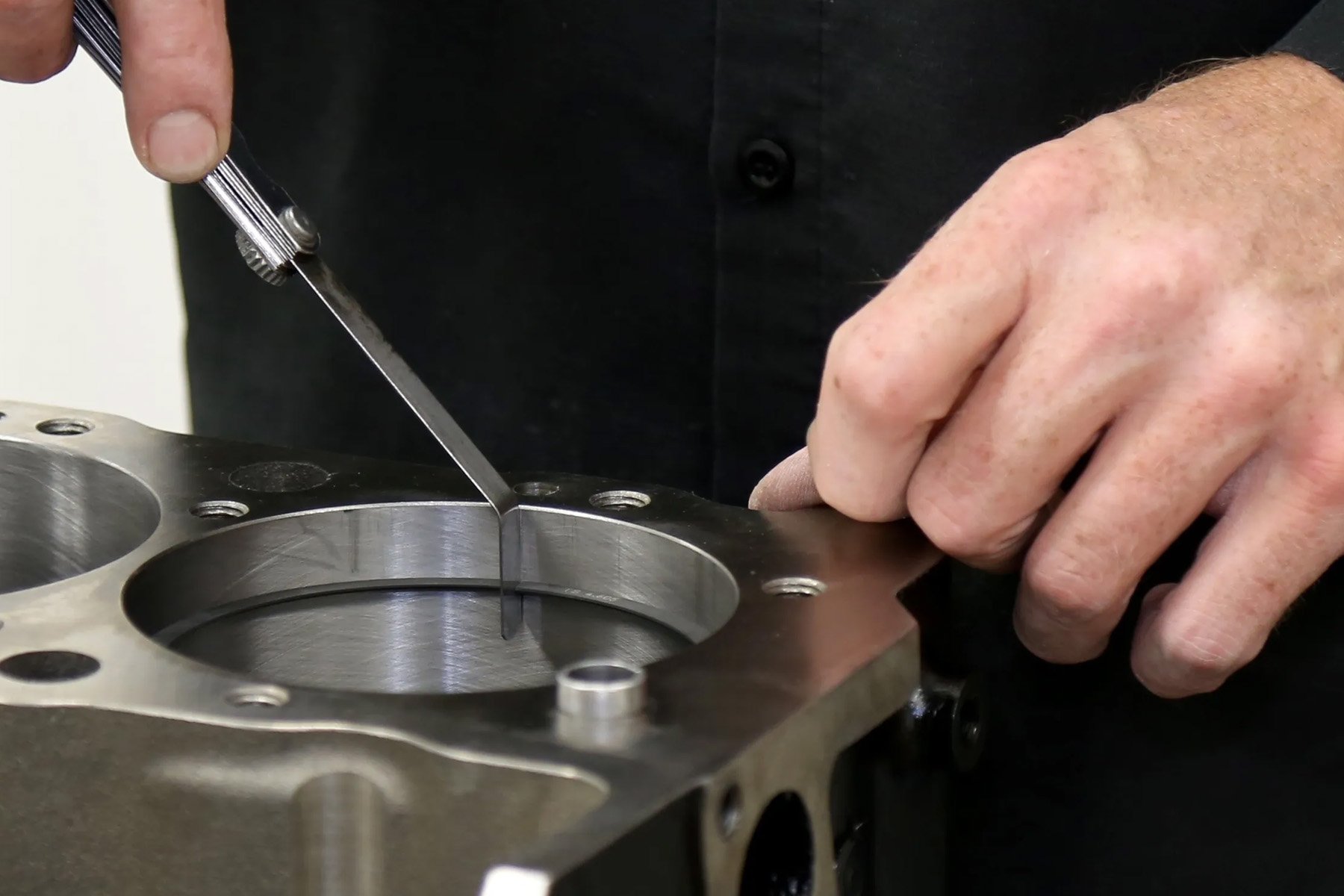
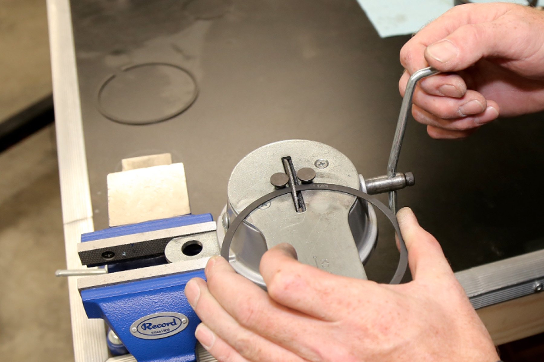
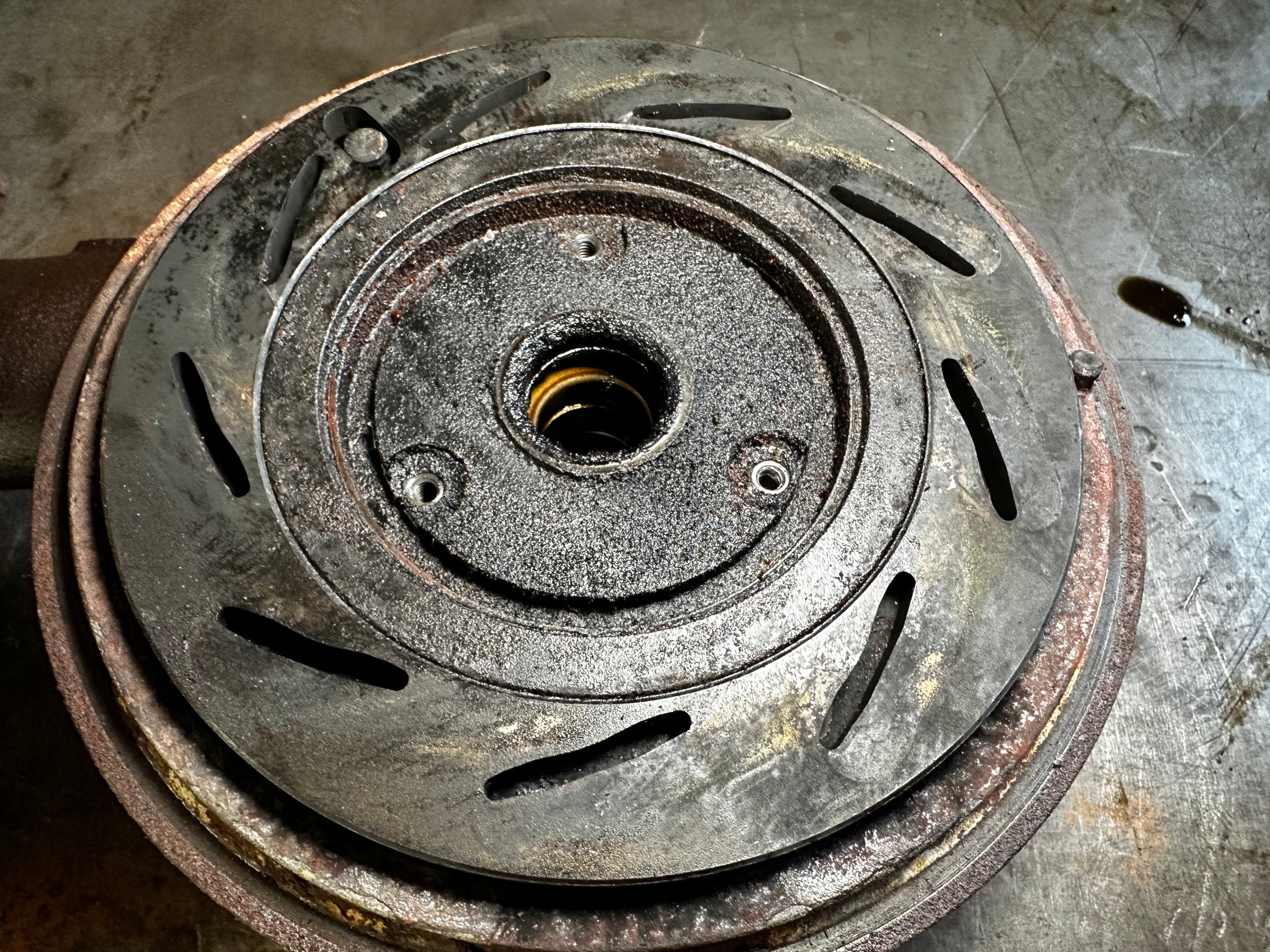
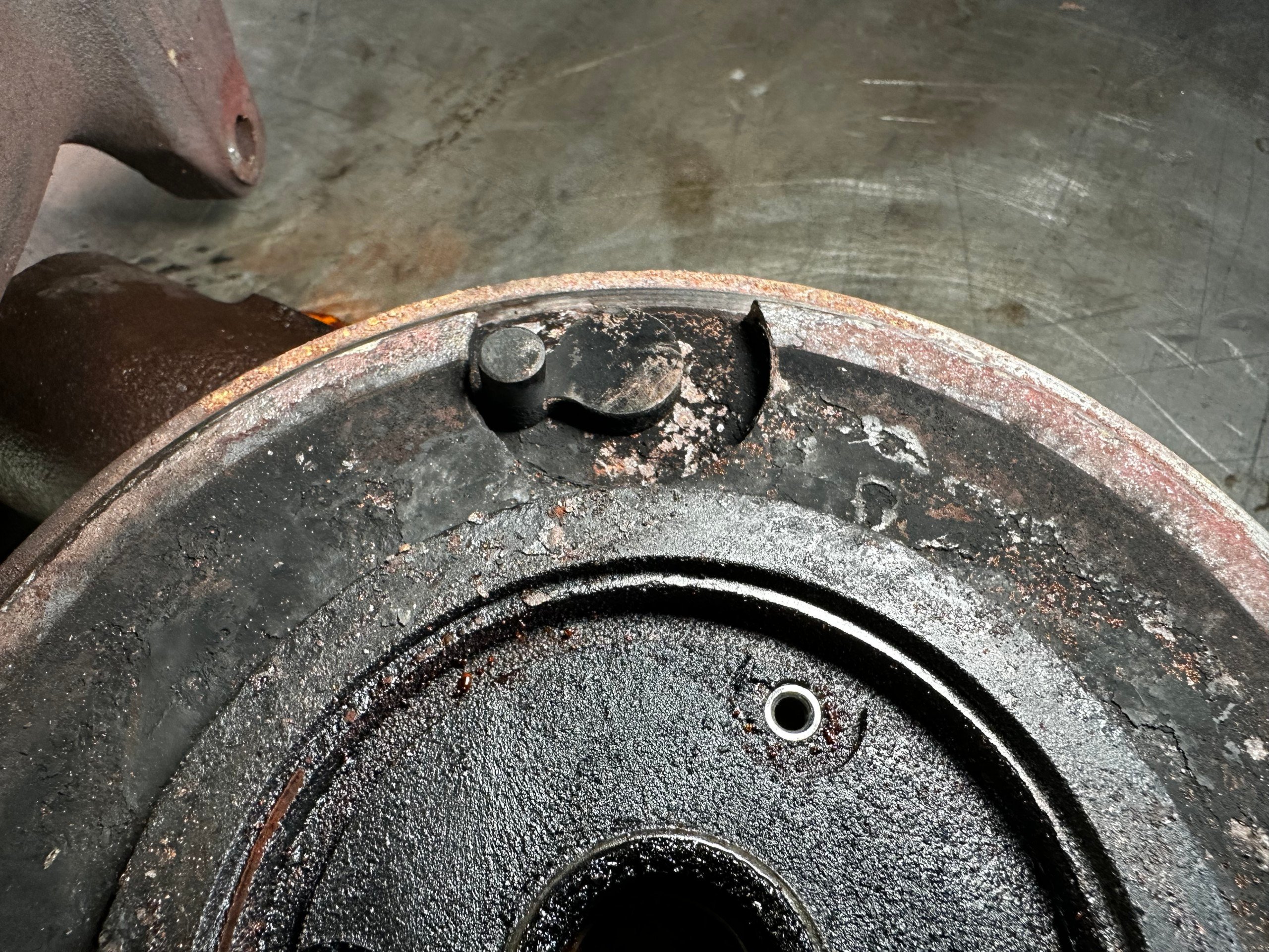
One of the ways Nichole and Damon have been able to prolong the longevity of their Civic’s screamer of an engine is to check bearing wear after events, and then tear the engine down for a full inspection every two to three events. This may seem overkill (not to mention extremely time-consuming) but it allows Nichole’s team to address any underlying issues early on, and ascertain where weaknesses may be festering.
For instance, in 2022, the Miss PSI team’s biggest stumbling block was getting a head gasket to survive multiple events. They found out this was due to the amount of traction control needed for short-track grip. By moving the entire engine program over to a billet B-Series block from Bullet Race Engineering, the team was able to improve block rigidity and head gasket performance. This was achieved by the block’s larger, 14mm head studs and the company’s signature beryllium copper “Fire Ring” gasket set.
Being one of the few XFWD cars running a wet-deck billet block, the Miss PSI team had to work around (and through) quite a few learning curves to get optimal performance out of this fresh setup. But after a few missteps, the team came out swinging at the World Series of ProMod and ran a top event ET with a 7.78 at 196mph. This was when the car secured that aforementioned “7th fastest XFWD in the world” title.
We don’t normally dyno the engine to max power, but estimate 1,600 wheel-horsepower, based on fuel consumption and trap speed. — Nichole Elff

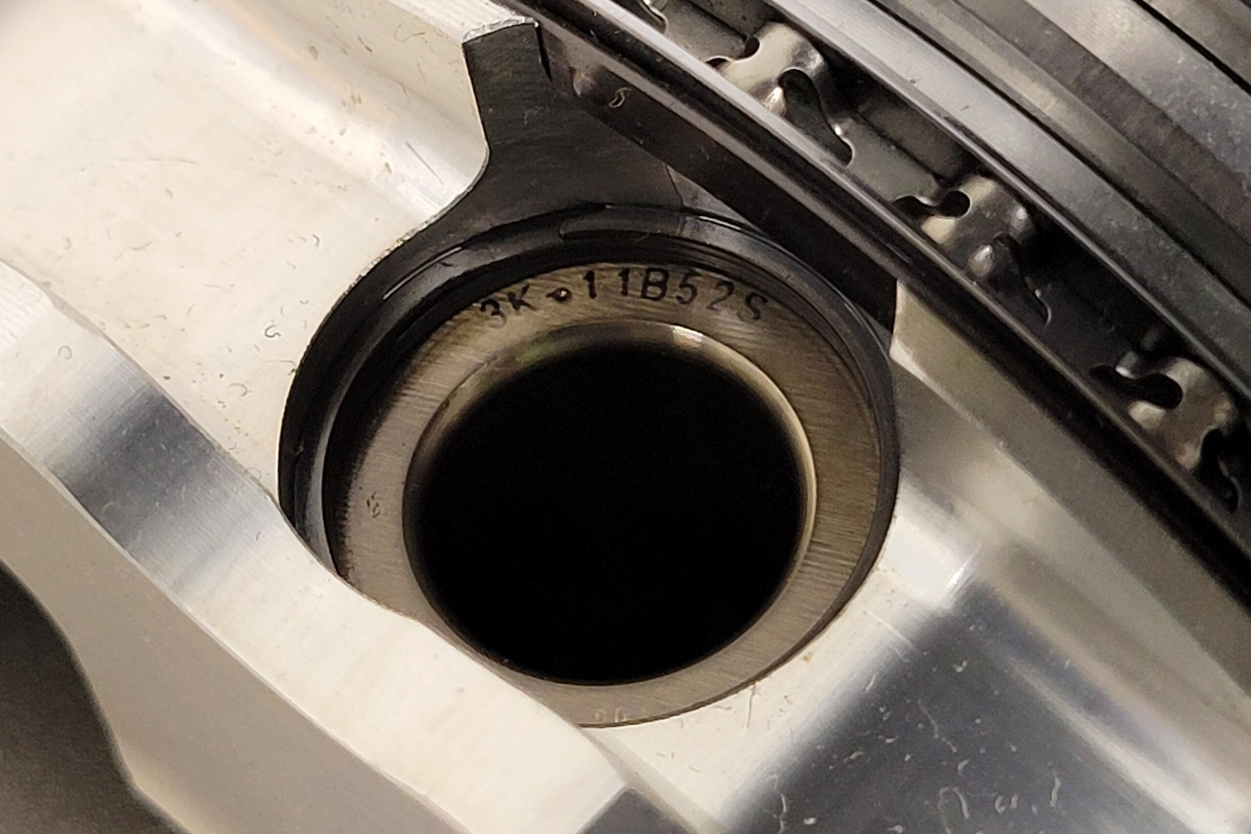
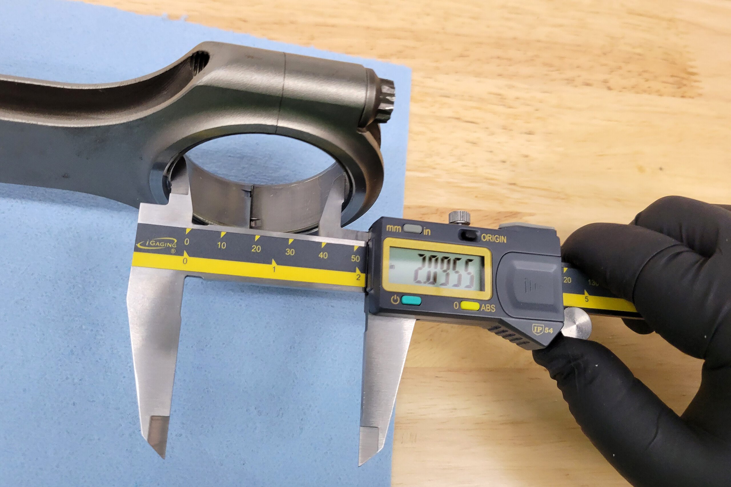
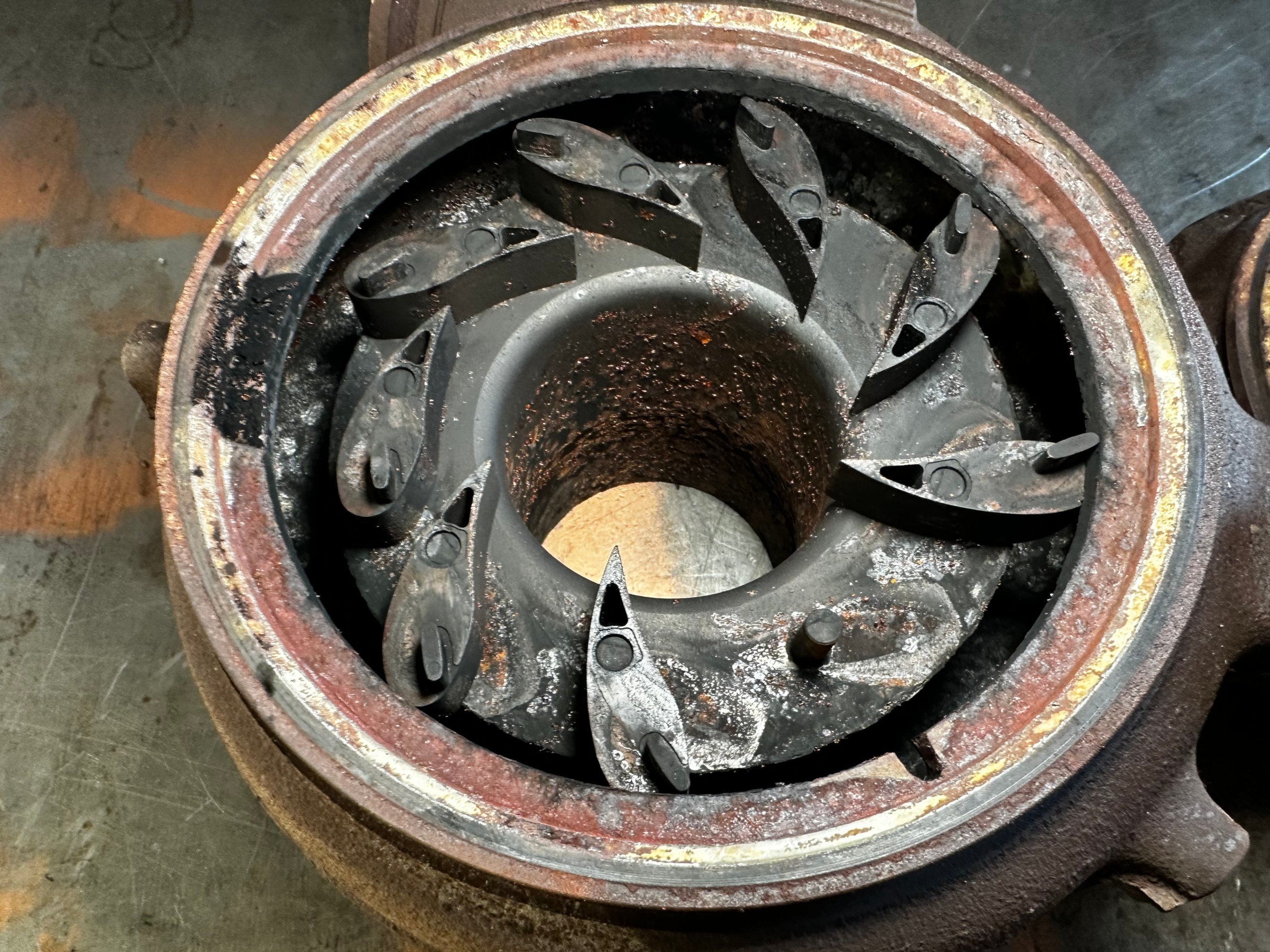
pMax Kote bearings from King Engine Bearings being installed into the Miss PSI Bullet Engineering billet B18 block, along with a set of BME aluminum rods.
Throughout the rest of the 2022 season, Nichole and her team continued to try fresh upgrades, with different rotating assembly combinations being the primary focus. Then, come mid-2023, the switch to pMax Kote main rod bearings from King Engine Bearings was made, which proved to be a very wise decision.
Remember a few paragraphs back, when we mentioned that checking the engine’s bearings after each event was a mandatory quality control procedure for this race team? Well just after the first event, the Miss PSI crew saw improved outcomes with that fresh King Bearings combo, with wear being minimized significantly. And so the team opted to run those same main bearings for all five of the final events, which in turn helped them win the 2023 FL2K XFWD Street class trophy, and a nice little chunk of change in prize money.

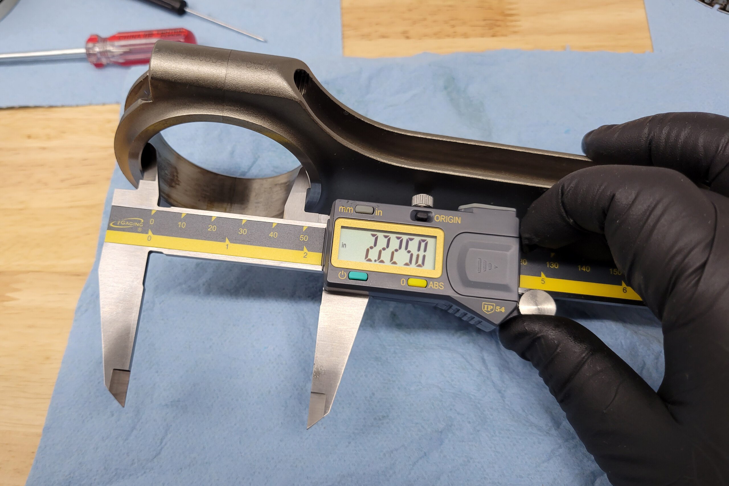
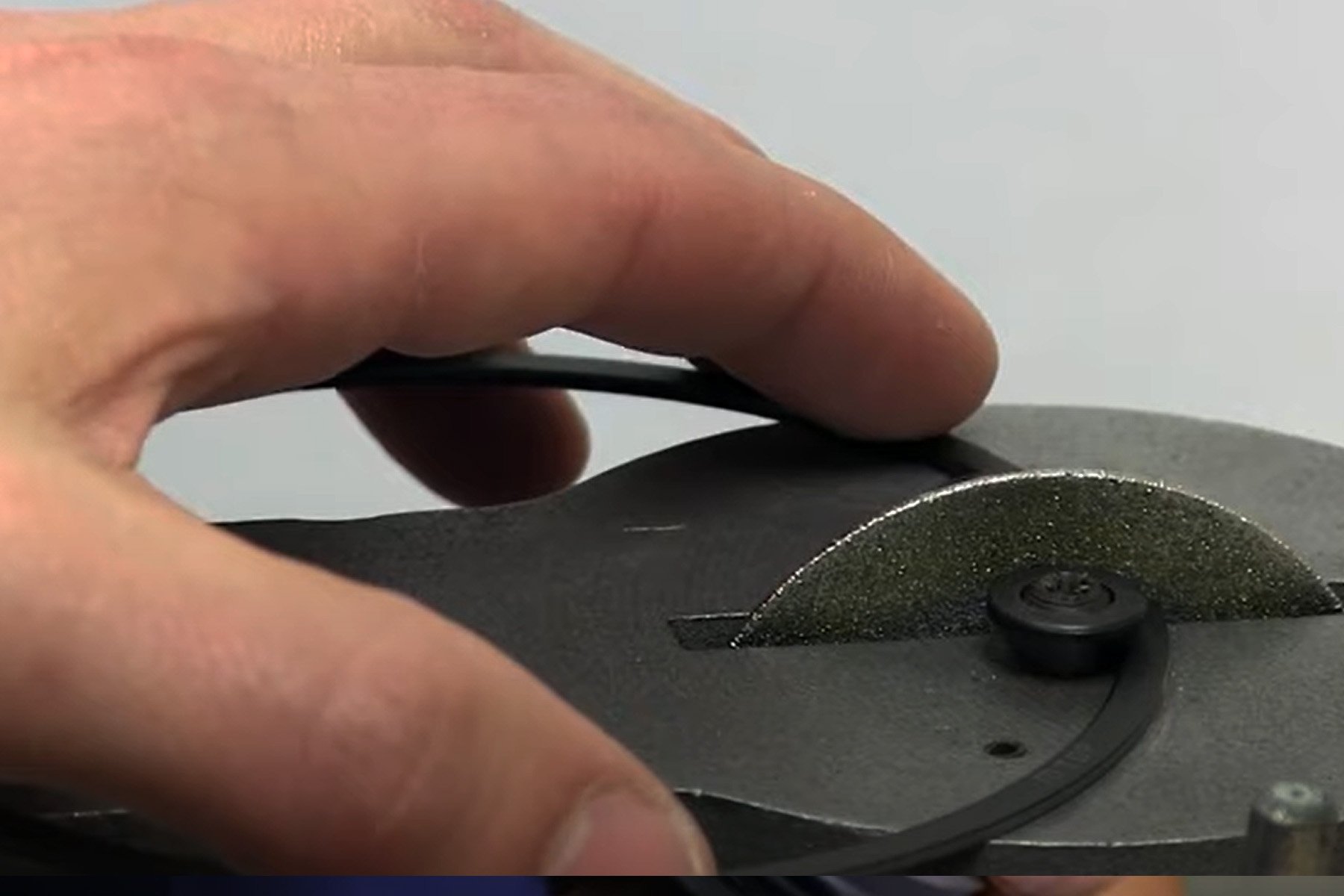
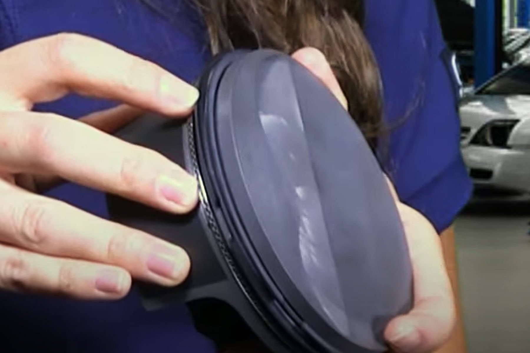
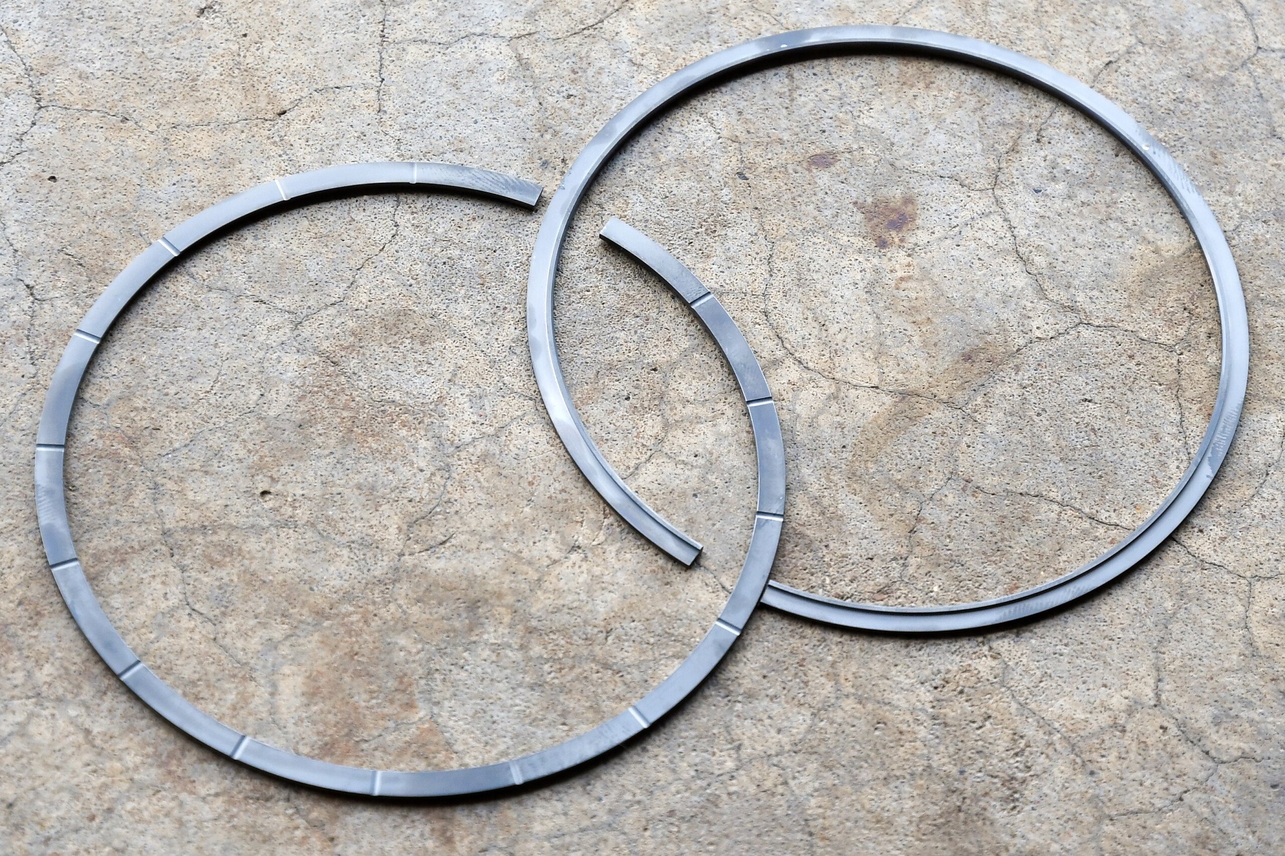
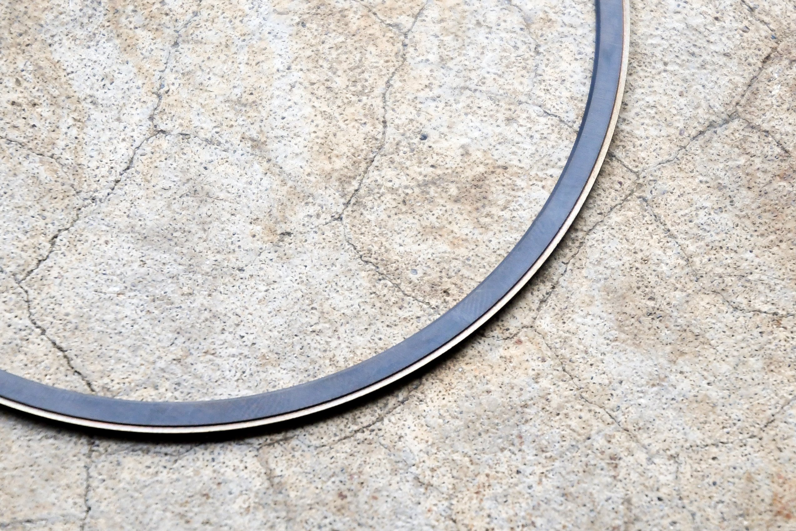
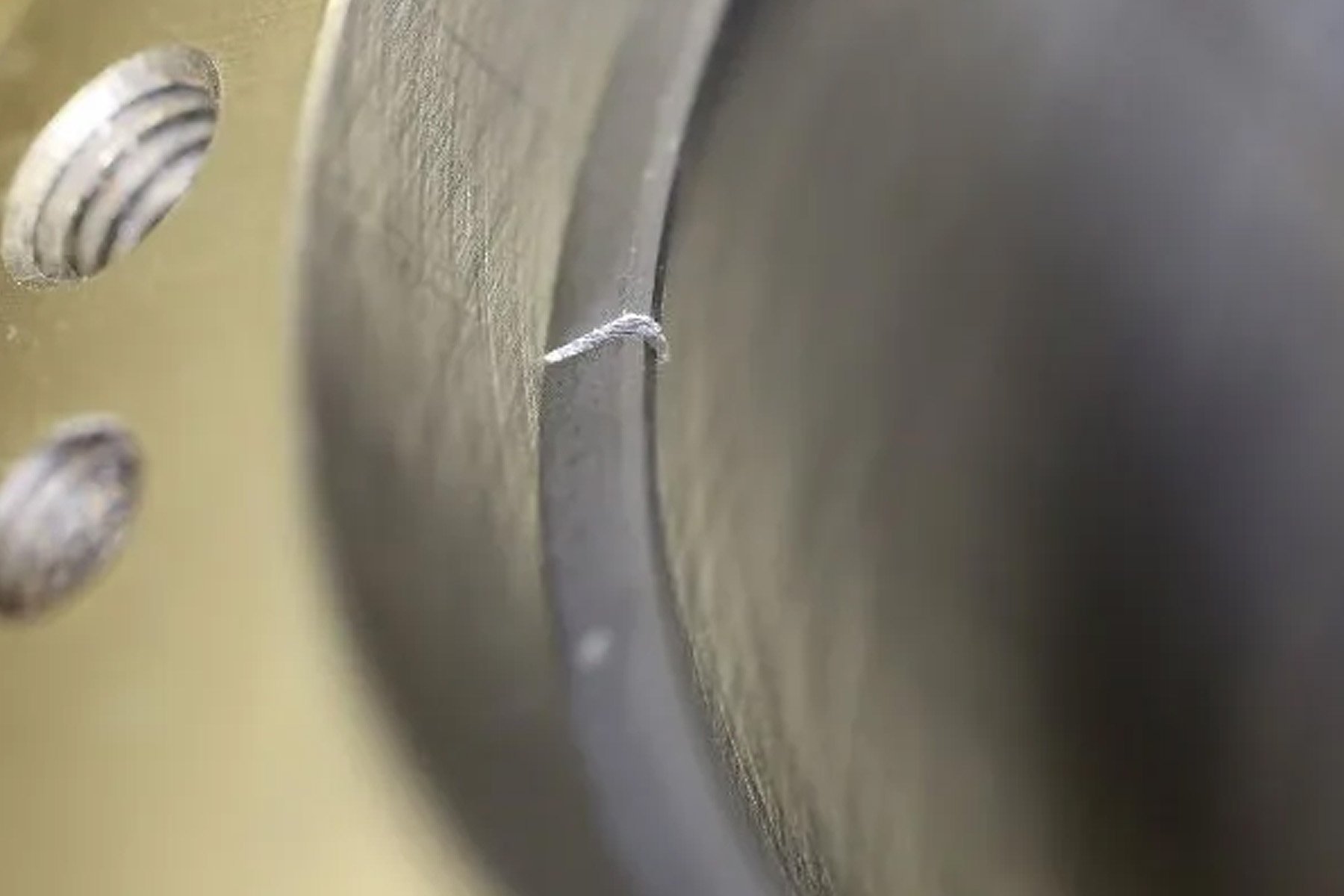
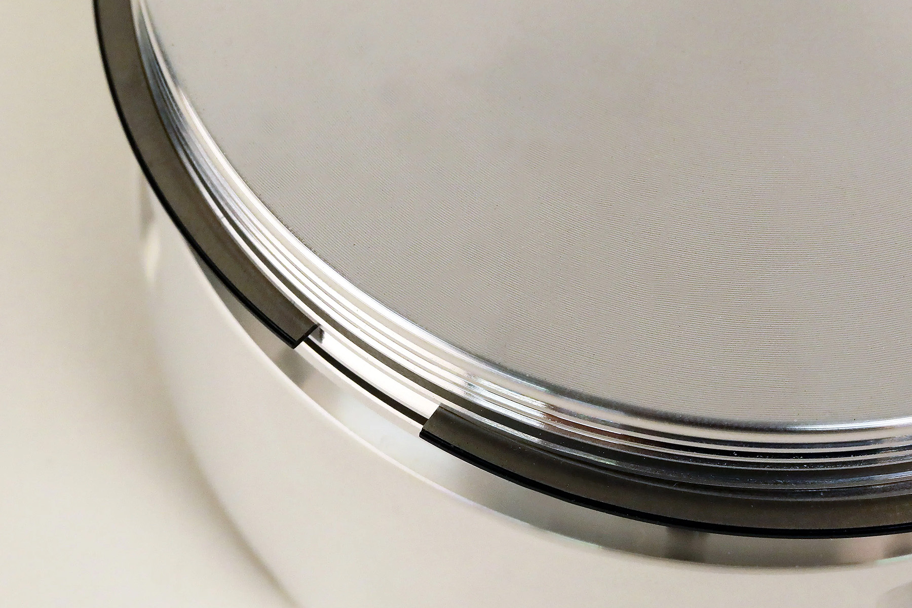
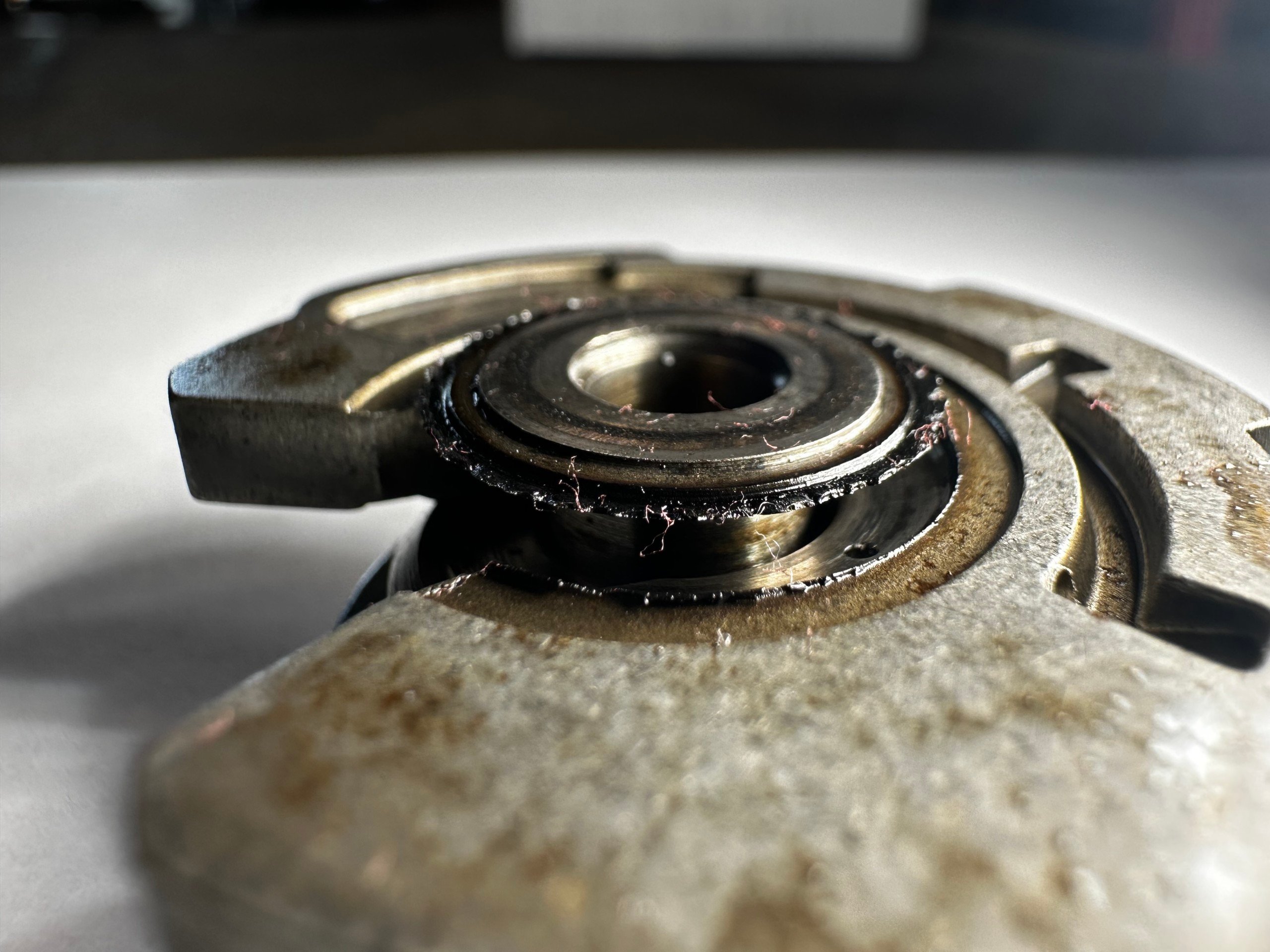
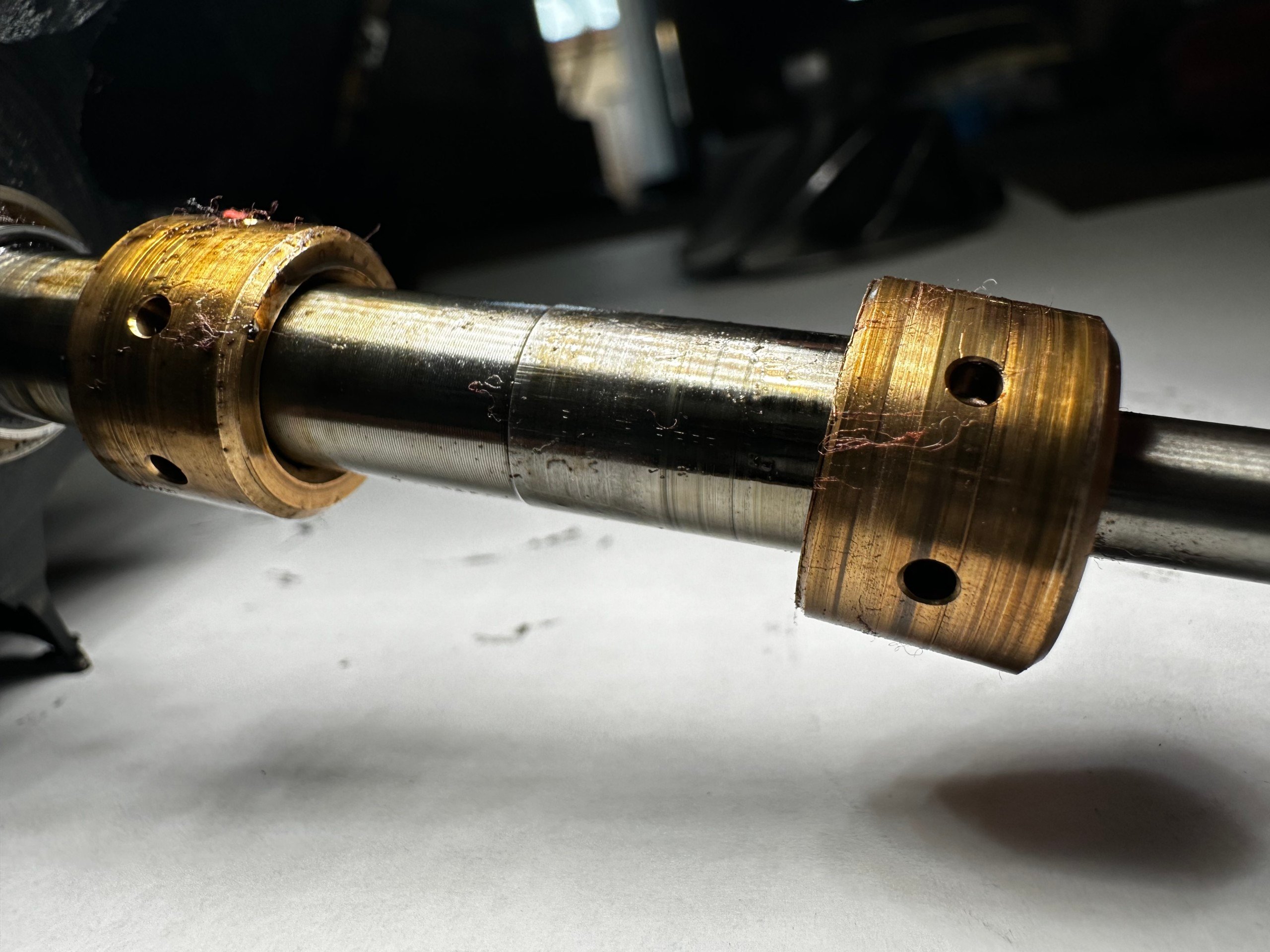
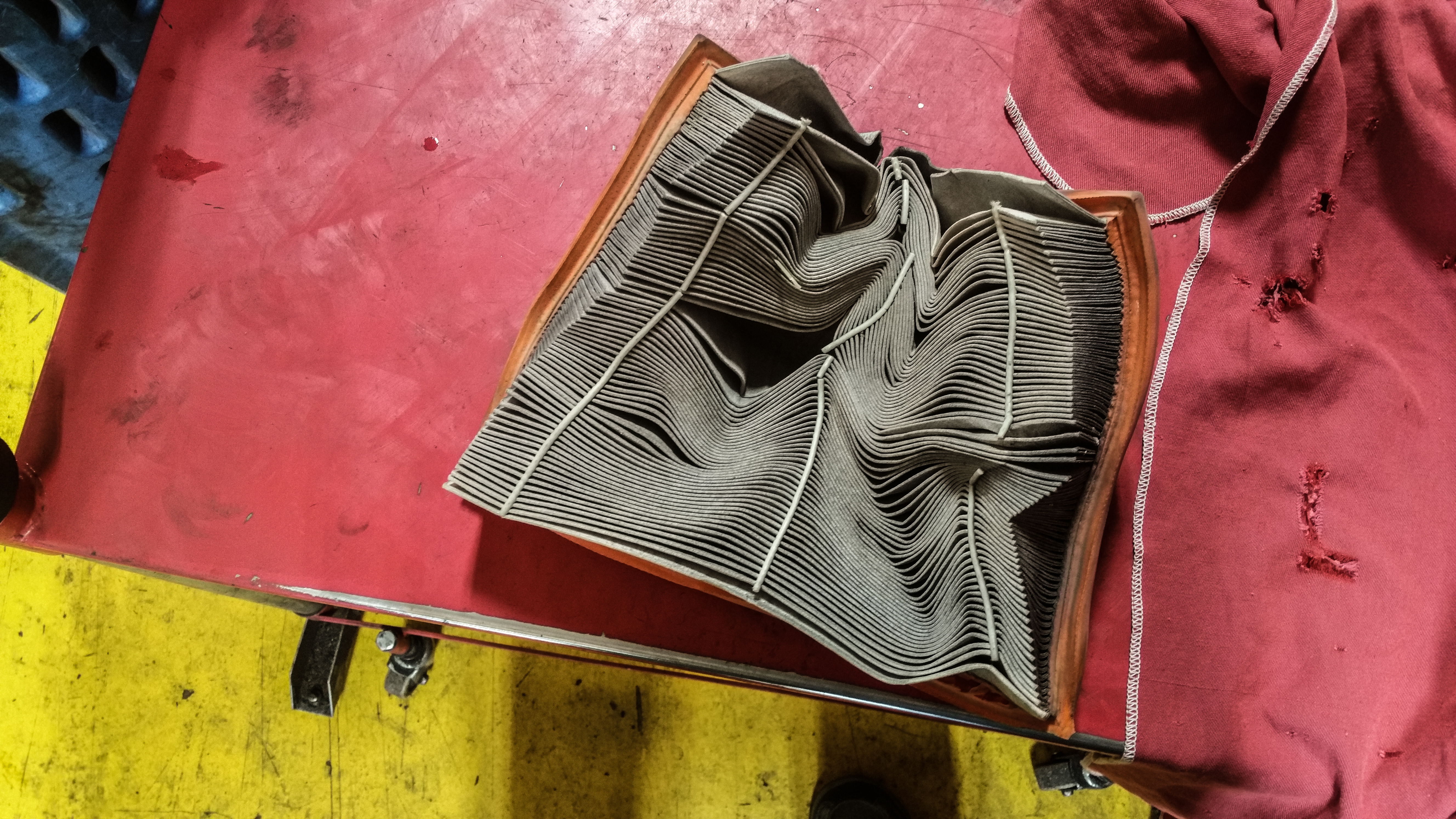
After each event, a full engine teardown takes place back at the shop. Here, you can see that the bearings previously used in the Miss PSI B18 (TOP) came out worn to hell and back after a single event. Meanwhile, very little coating seems to have been removed from the units from King Engine Bearings.
The Importance of Being “Over-bearing”
Being that Damon is the mad scientist behind the keys to this machine, Nichole explains that his “forever job” is finding the optimal tune for the track that can bring that knife-edge balance of performance that his bride requires. Just another husband and wife team building a 1,500-plus horsepower Honda Civic in-house for fun.
And while Nichole counts herself extremely fortunate to have a partner who supports her “crazy passion,” she knows that he too enjoys taking his knowledge from Indycar and Sportscar racing and applying these innovative solutions to the Miss PSI race program. Together with the help of their small, but dedicated village, this car has skyrocketed to the top in record time.

According to Damon, switching the little Honda over to the pMax Kote series from King Engine Bearings in the middle of the 2023 season has been one of the most surprising game-changers for the team. Up until that point, it was common for the rod bearings to wipe the coatings right off after just a single event, whereas these pMax Kote units looked brand new race after race.
Not only does this specialized coating withstand the harsh environment found within this force-fed race engine, but the shape of the bearing itself refuses to warp like other products. This has resulted in greater reliability and performance as well.
The confidence that products such as these provide has allowed the team to push the platform harder than ever before, and set their sites on even greater heights in the 2024 race season. Nichole and Damon Elff aren’t done yet. Apparently, they now have their sights set on making Nichole the first XFWD driver in history to pilot a car to 200mph. No small feat for a little 1.9-liter four-cylinder engine.

MissPSI XFWD Engine Spec Sheet
Owner: Nichole Elff
Age: 40
Occupation: Process Development Manager
Engine (Model or Family): Honda B18C
Builder: 4 Piston Cylinder Heads
Machine Shop (If different from builder): N/A
Total Displacement: 1.9 liters
Bore x Stroke: 84mm x 89mm
Block: Bullet Engineering Billet B-series
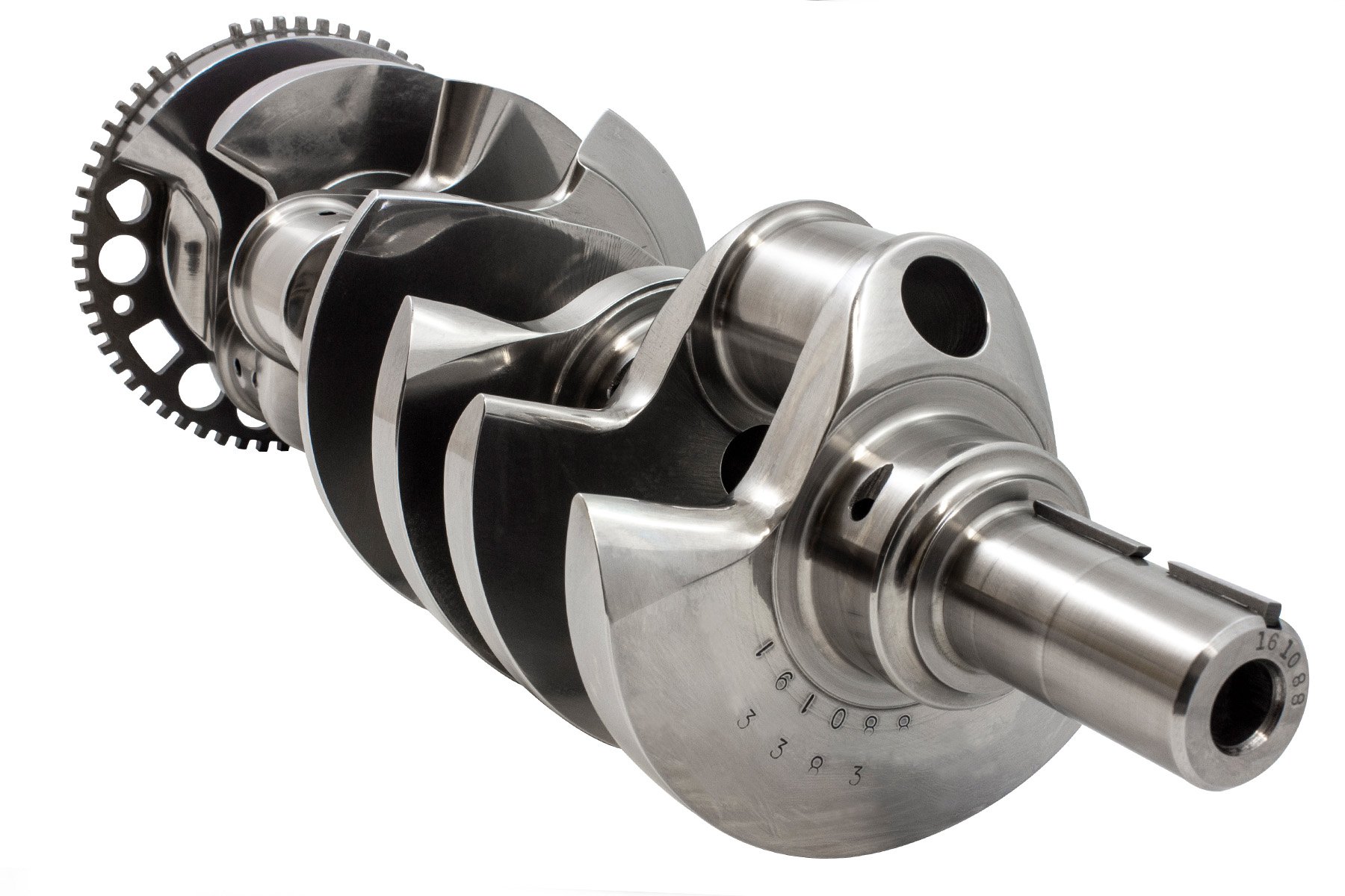
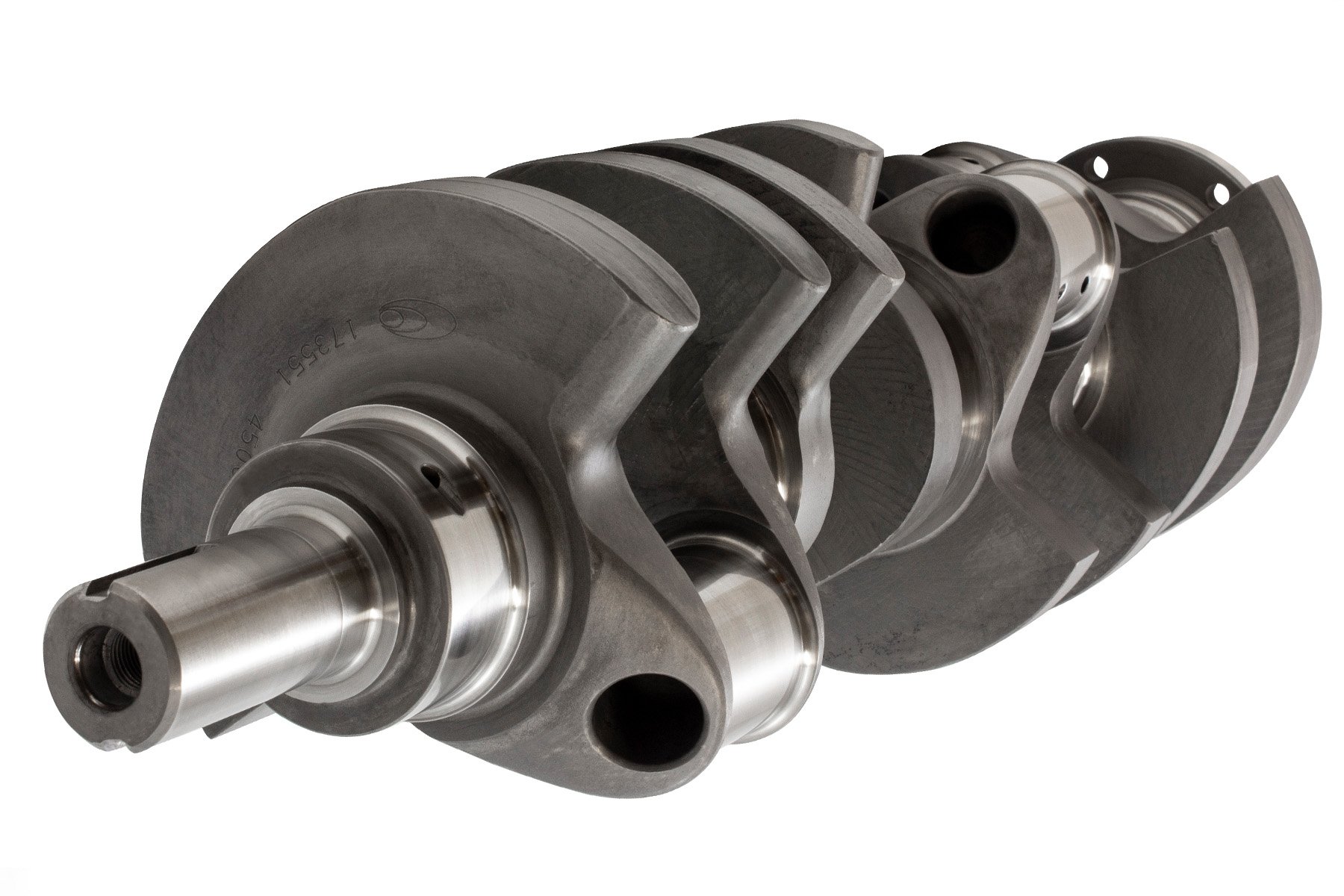
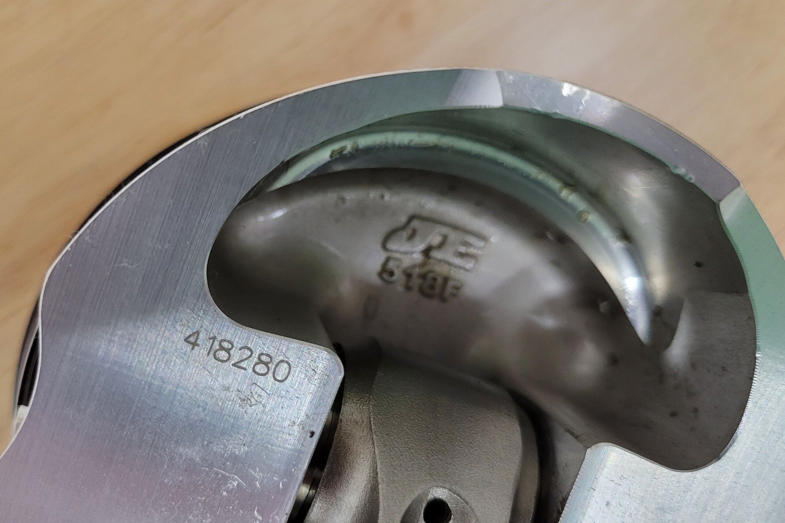
Crankshaft: OEM B18B
Bearings: King Racing PMaxKote
Rods: BME Aluminum
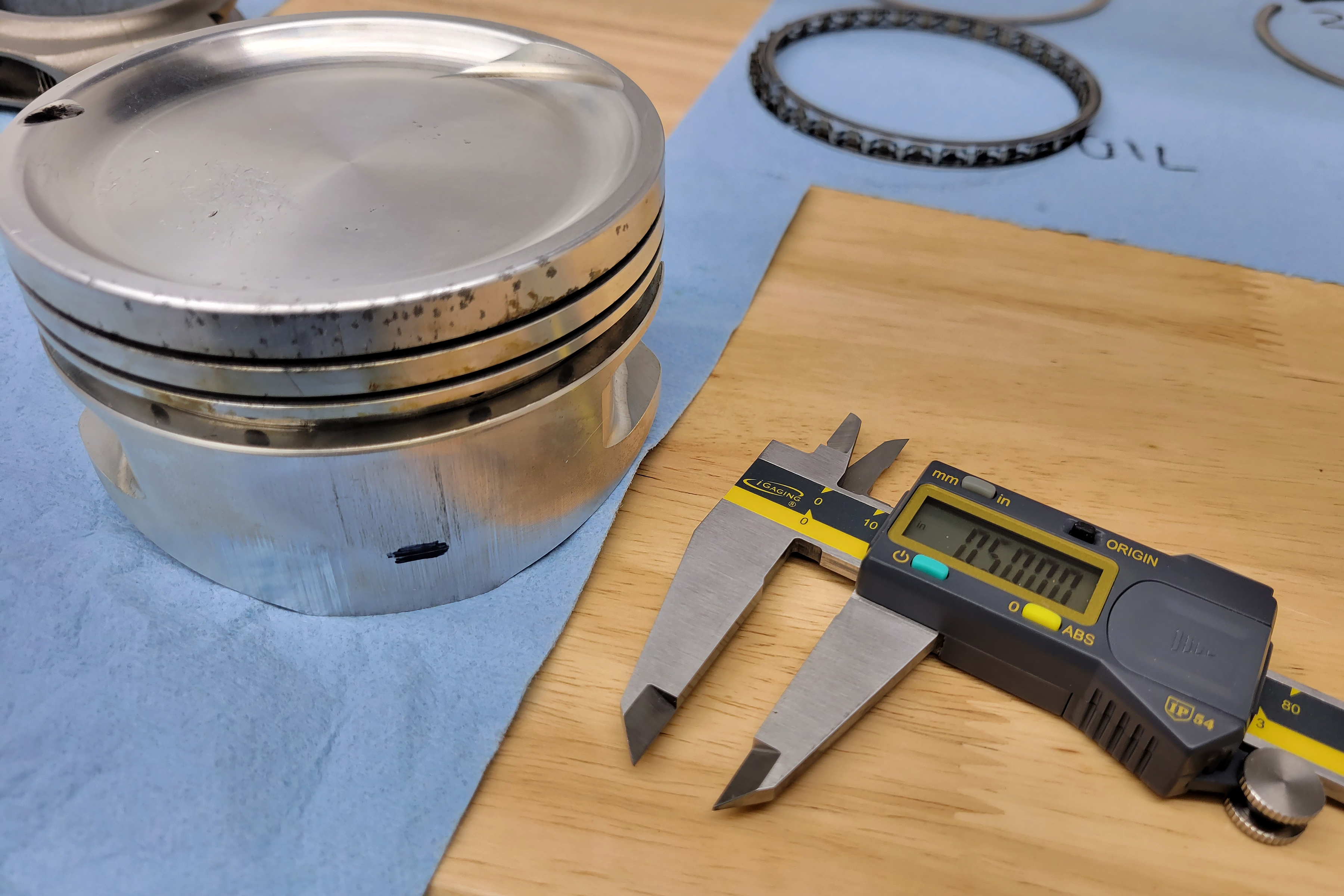
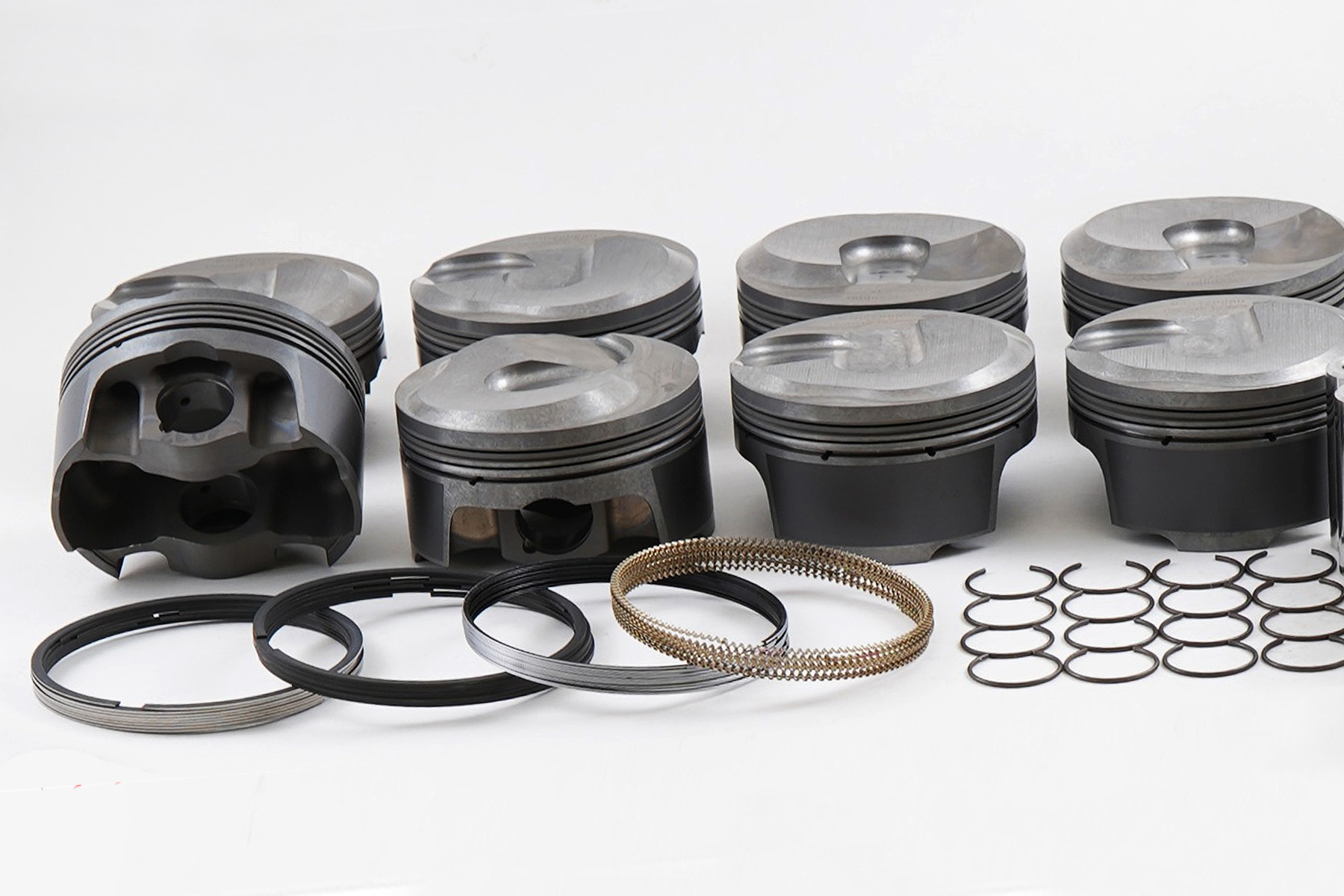
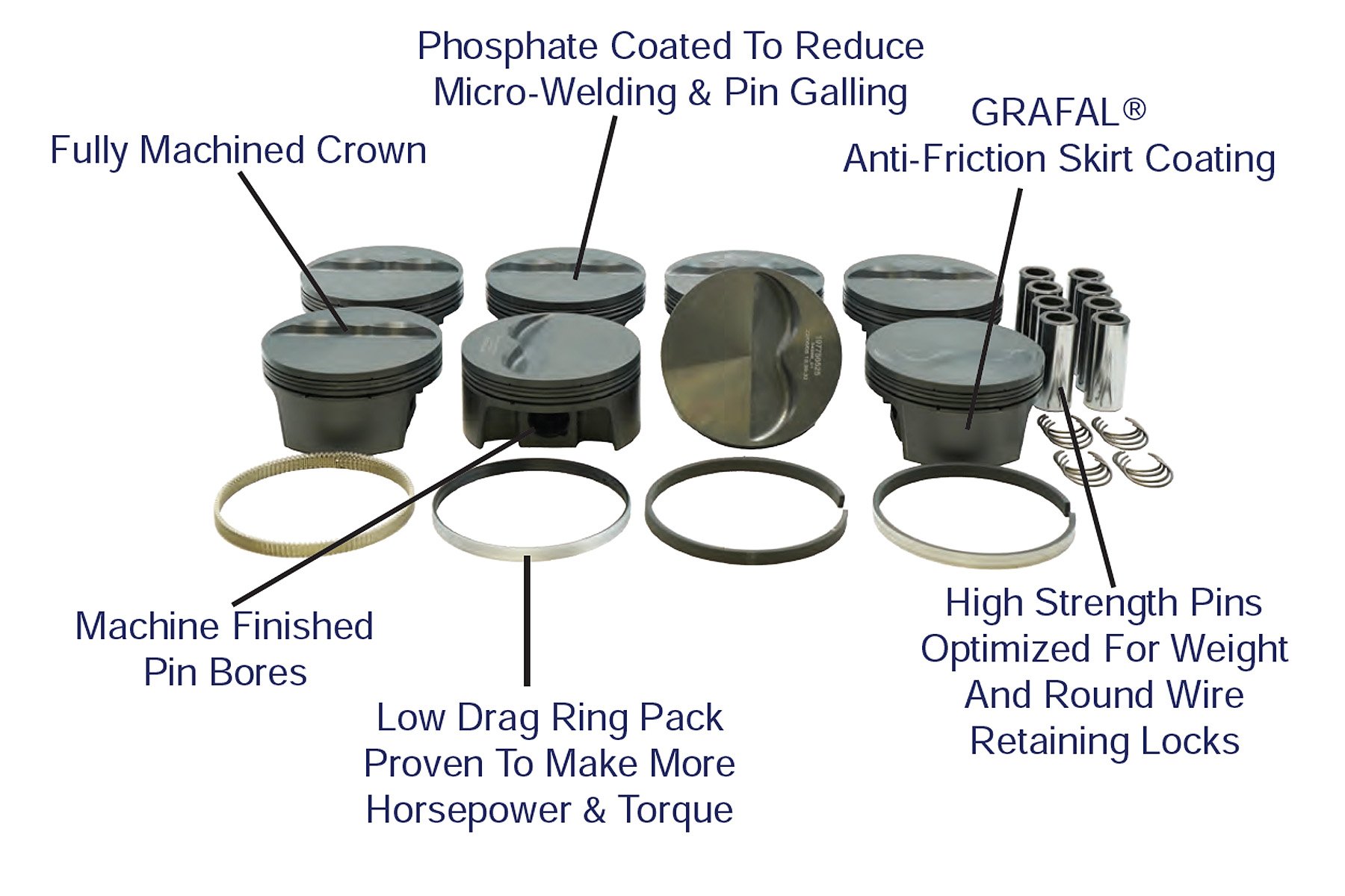
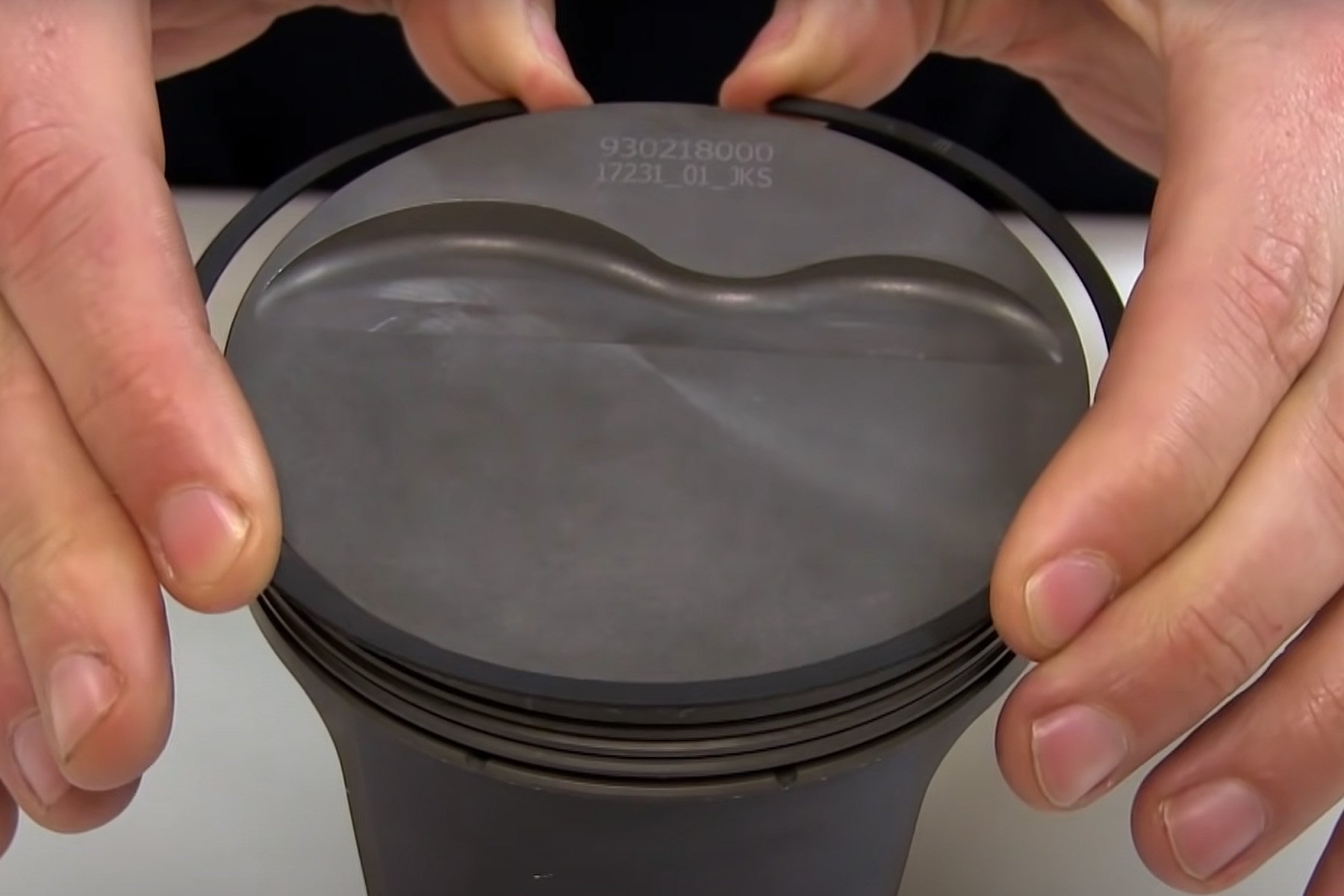
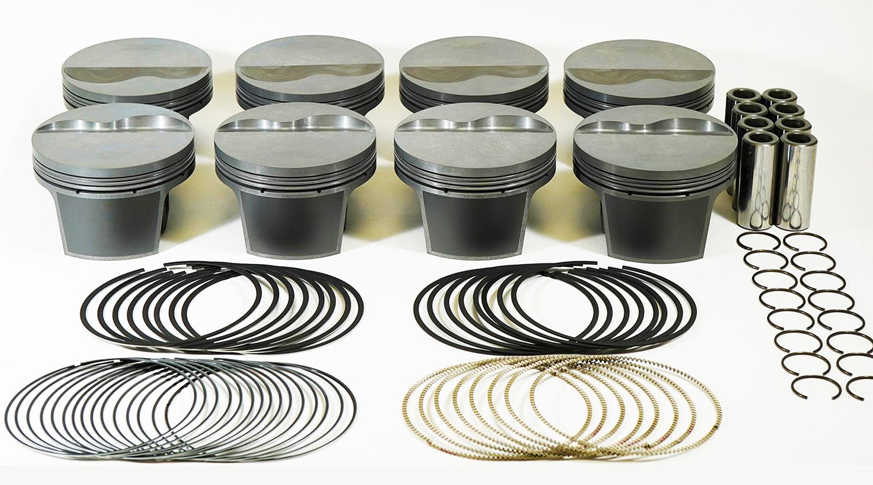
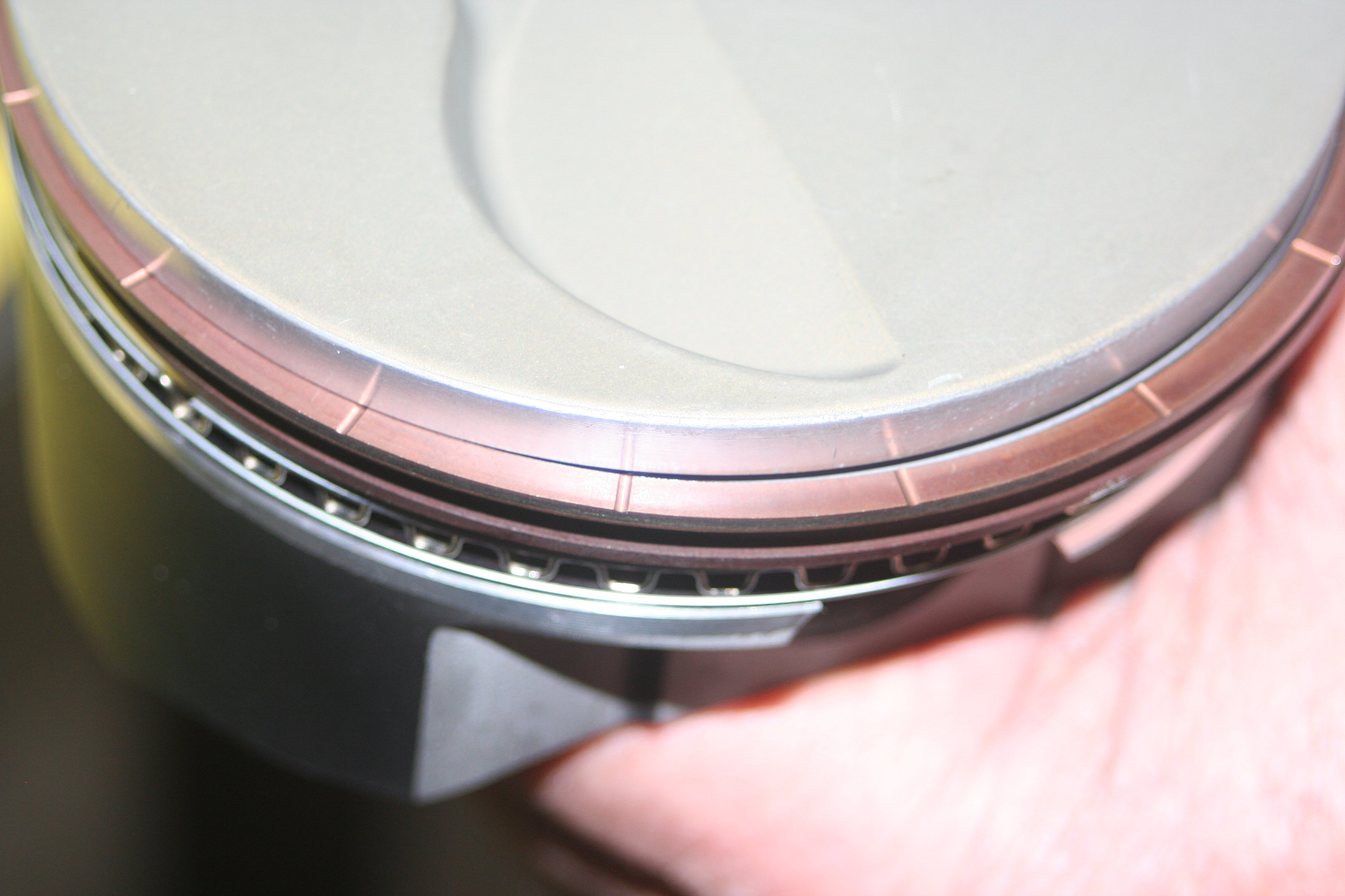
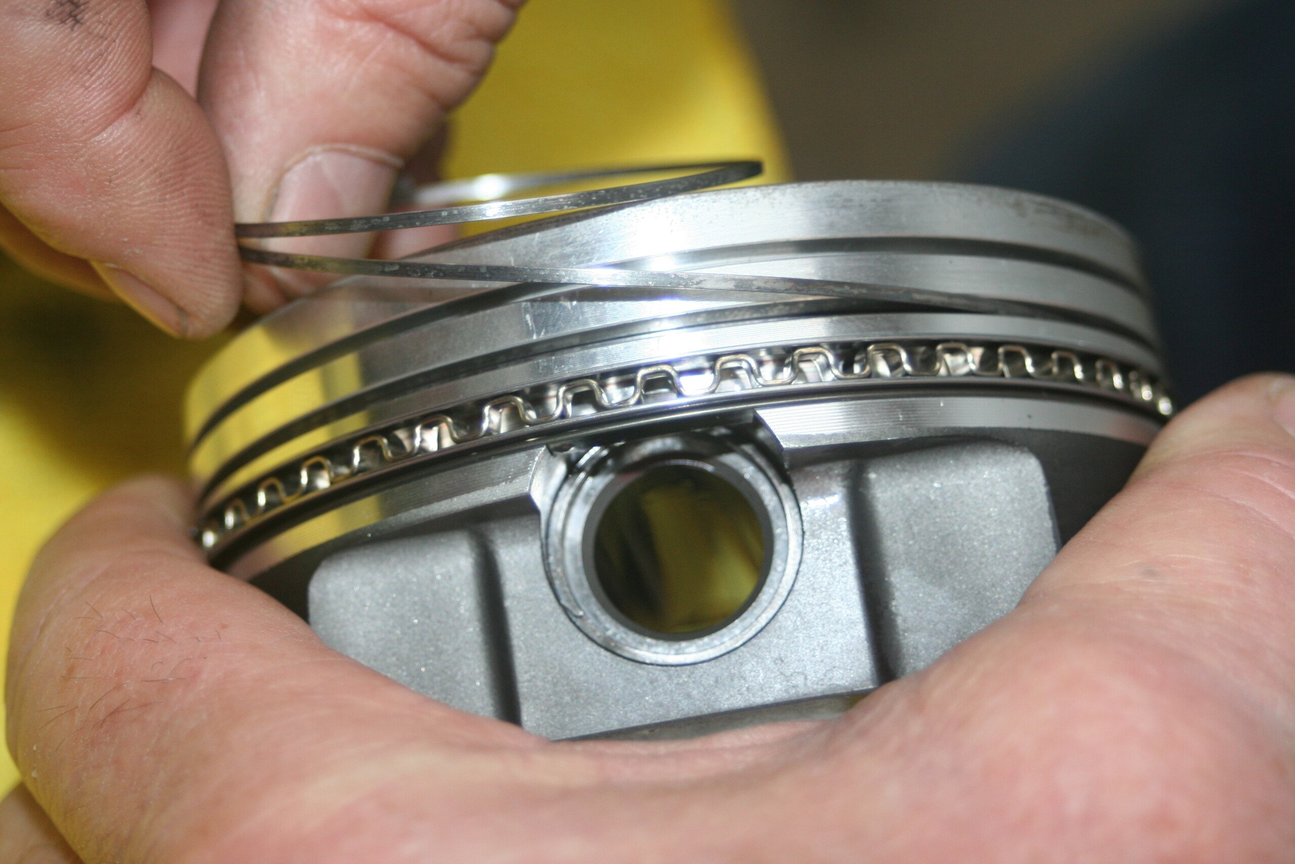
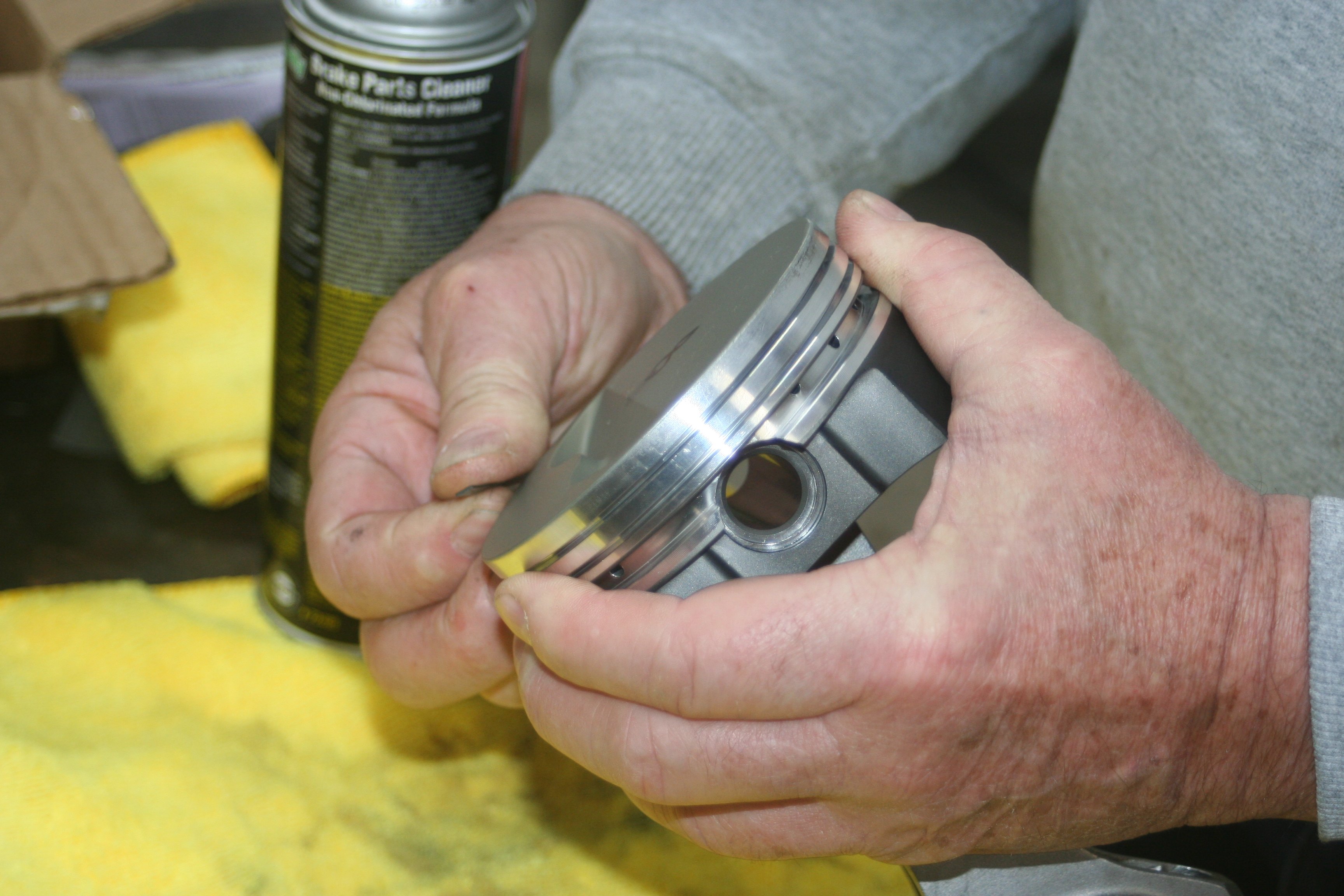
Pistons: CP
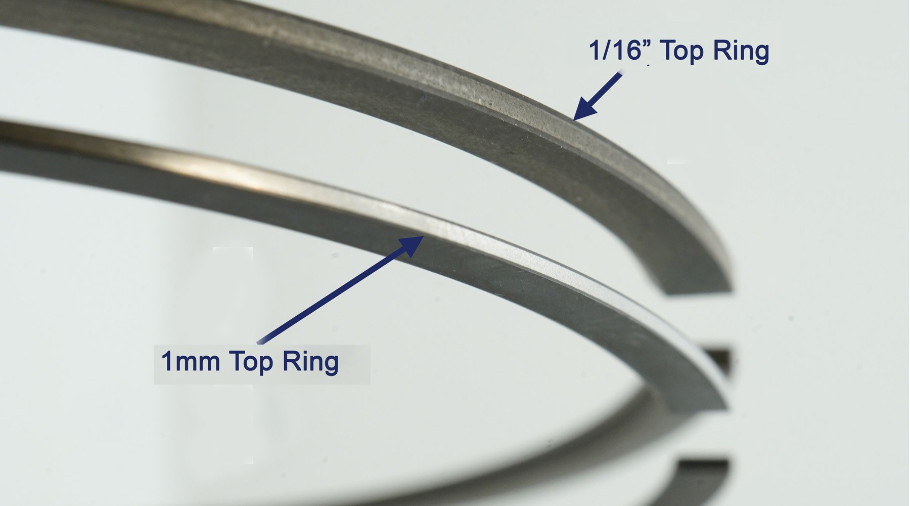
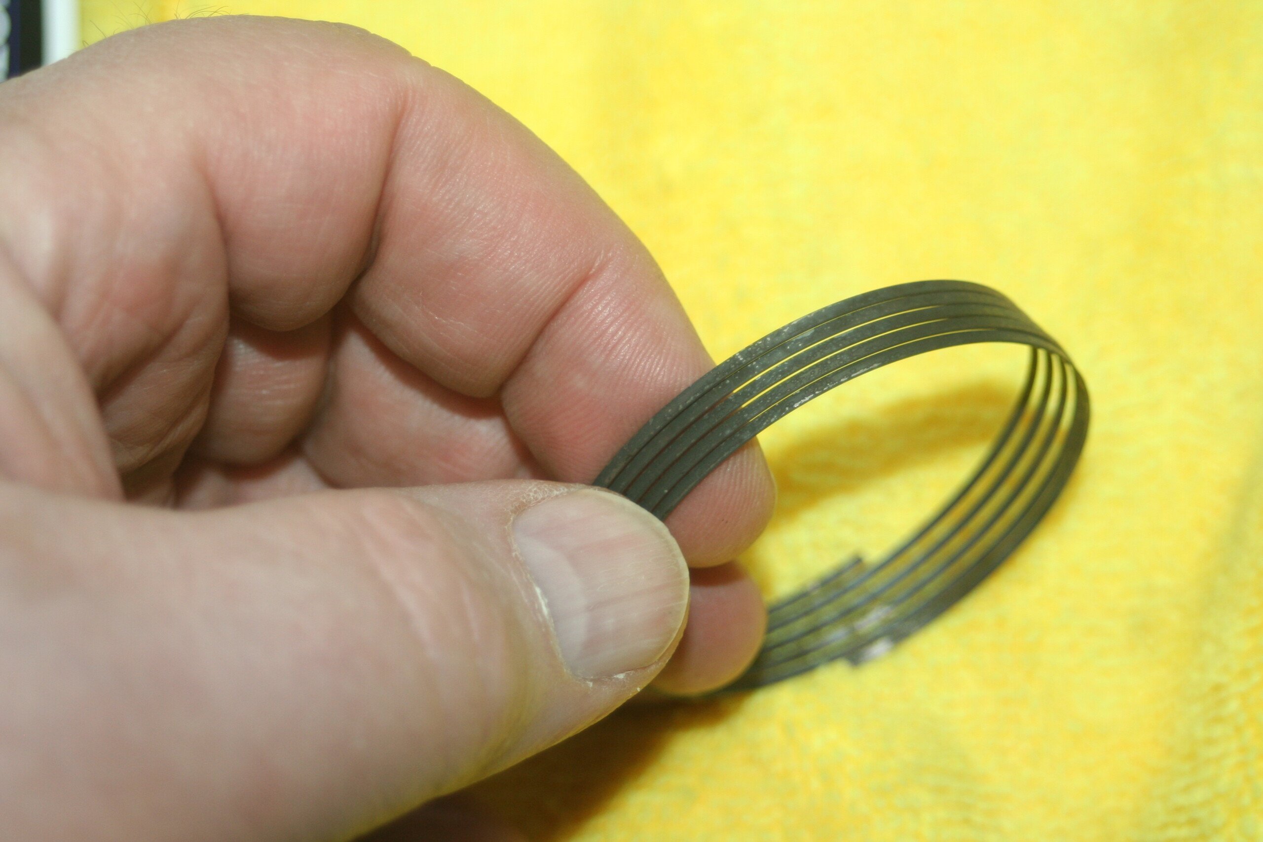
Rings (size, type, brand): Proprietary
Oil Pump: 4 Piston ported OEM pump
Oil Pan: Moroso
Timing Set: Gates timing belt & Ramey Racing adjustable cam gears
Cylinder Heads: 4Piston Outlaw Front Runner CNC Cylinder Head, 6mm Stub nose guides, A3
Beryllium valve seats
Port Work: 4 Piston
Valves: Ferrea super alloy plus valves, 4P 6mm exhaust valves,
Valve Springs: Ferrea valve springs, retainers, and locks
Flow numbers: will need to ask 4 Piston
Camshaft(s): Web Cams Turbo B-series roller camshaft
Rockers: Ferrea roller rocker
EFI System: Motec M150
Injectors: Injector Dynamics
Throttle Body: Proprietary
Intake Manifold: Skunk 2 Ultra Race Manifold
Headers: Speedfactory Forward Facing Manifold
Power Adder: Precision Next Gen R 73.9 turbo
Ignition System: Motec Ignition 1A coils
Fuel System: Weldon Mechanical fuel pump
Fuel Type: Methanol
Horsepower: 1,500 whp